boot HONDA INTEGRA 1998 4.G Owner's Guide
[x] Cancel search | Manufacturer: HONDA, Model Year: 1998, Model line: INTEGRA, Model: HONDA INTEGRA 1998 4.GPages: 1681, PDF Size: 54.22 MB
Page 711 of 1681
Suspension
Special Tools ............. 18-2
Component Location
lndex ................ ...... 18-3
Wheel Alignment
Caster ............... ...... 18-4
Camber .................. 18-4
Front Toe Inspection/
Adjustment ........ 18-5
Rear Toe Inspection/
Adiustment ........ 18-5
Turning Angle Inspection ................ 18-6
^'heel/Hub Inspection
tBearing End Play .............................. 18-7
Wheel Runout ....... 18-7
Front Suspension
Torque Specifications ...................... 18-8
Knuckle/Hub
lllustrated lndex .........,................. 18-9
Knuckle Removal ......................... 18-11
Wheel Bearing Replacement ...... 18-14
Knuckle 1nsta11ation ..................... 18-16
Lower Ball Joint Replacement ....... 18-17
Ball Joint Boot Replacement .......... 18-19
Suspension Arms
Removal/lnspection .................... 18-20
lnstallation ......... 18-21
Front Dampel
Removal ................. 18-22
Disassembly/lnspection ............. ..... 18-22
Reassembly ........... 18-24
fnstaffation ............. 1A-25
Rear Suspension
Torque Specifications ...................... 18-26
Hub Bearing Unit
f f f ustrated lndex ................ ........... 18-27
Removal ............. 18-29
lnstallation ......... 18-30
Suspension Arms
Removal/lnspection .................... 18-32
lnstallation ......... 18-34
Rear Damper
Removal ................. 18-36
Disassembly/lnspection .................. 18-37
Reassembly ........... 18-39
Installation ............. 18-40
Page 712 of 1681
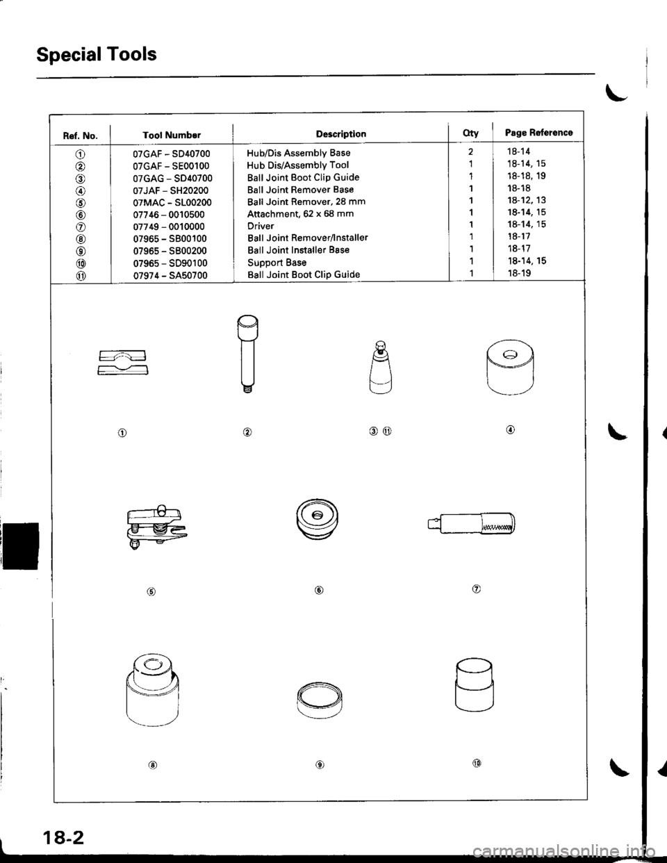
SpecialTools
t
Ref. No. I Tool Numb€rD63criptionoty I Page Relerence
O I oTcAF-sD4o7oo
@ | oTGAF-sEooloo
O I 0TGAG-sD4o7oo
@ 0TJAF - sH2o2oo
O I oTMAc - sLoo2oo
O | 07746 - oolosoo
@ | 07749-ooloooo
@ | 07965-sBooloo
@ | 0796s-sBoo2oo
@ I 07965-sDgo1oo
o 07974 - SA50700
Hub/Dis Assembly Base
Hub Dis/Assembly Tool
Ball Joint Boot Clip Guide
Ball Joint Remover Base
Ball Joint Remover,2S mm
Attachment, 62 x 68 mm
Oriver
Ball Joint Remover/lnstaller
Ball Joint Installer Bsse
Support Base
Ball Joint Boot Clip Guide
2 | 18-14
1 | 18-14, 15
1 | 18-1s, 1e
1 | r8-r8
1 I 1A-12.13
1 18-14. 15
1 I 18-14, 15
r I r8-r7
1 | 18-17
r | 18-14. rs
r I 18-19
re
F=:
E
.E{
L-]
o@
I
o@@
L-€tr
F@
rr--ml
@@o
d sJ4.'
Y@
a
ti
@€)@
1A-2
Page 715 of 1681
\
Front Toe Inspection/AdjustmentRear Toe Inspection/Adjustment
NOTE: Use commercially-available computerized four
whesl alignment equipment to measure wheel align-
ment (caster, camber, toe. and turning angle). Follow
the equipment manufacturer's instructions.
1.
2.
Check the tire pressure.
C€nter steering wheel spokes.
Check the toe with the wh€els pointed straight
ahead.
Front to6: 0 i 2 mm (0 t 1/16 in)
- lf adjustment is required. go on to step 4.
- lf no adjustment is required, remove alignment
equrpm€nr,
Loosen the ti€-rod locknuts and turn both tie-rods in
the same direction until the front wheels are in
straight ahead position.
Turn both tie-rods equally until the toe reading on
the turning radius gauge is correct.
After sdjusting, tighten the tie-rod locknuts.
NOT€: Reposition the tie-rod boot if it is twisted or
displaced.
TIE-ROD LOCKNUT14 x 1.5 mm
6.
a
NOTE: Use commercially-available computerized four
wheel alignment equipment to measure wheel align-
ment (caster, camber, toe, and turning angle), Follow
the equiDment manufacturer's instructions.
1. Release parking brake.
NOTE:
. Measure difference in toe measurements with
the wheels pointed straight ahead.
. lf the parking brake is engaged. you may get an
incorrect reading.
Rear toe-in: 2 11 mm l1l16 i 1/15 in)
- lf adjustment is required, go to step 2.
- lf no adjustment is required, remove alignment
equipment.
Before adjustment, note the locations of adjusting
bolts on the right and left compensator arms.
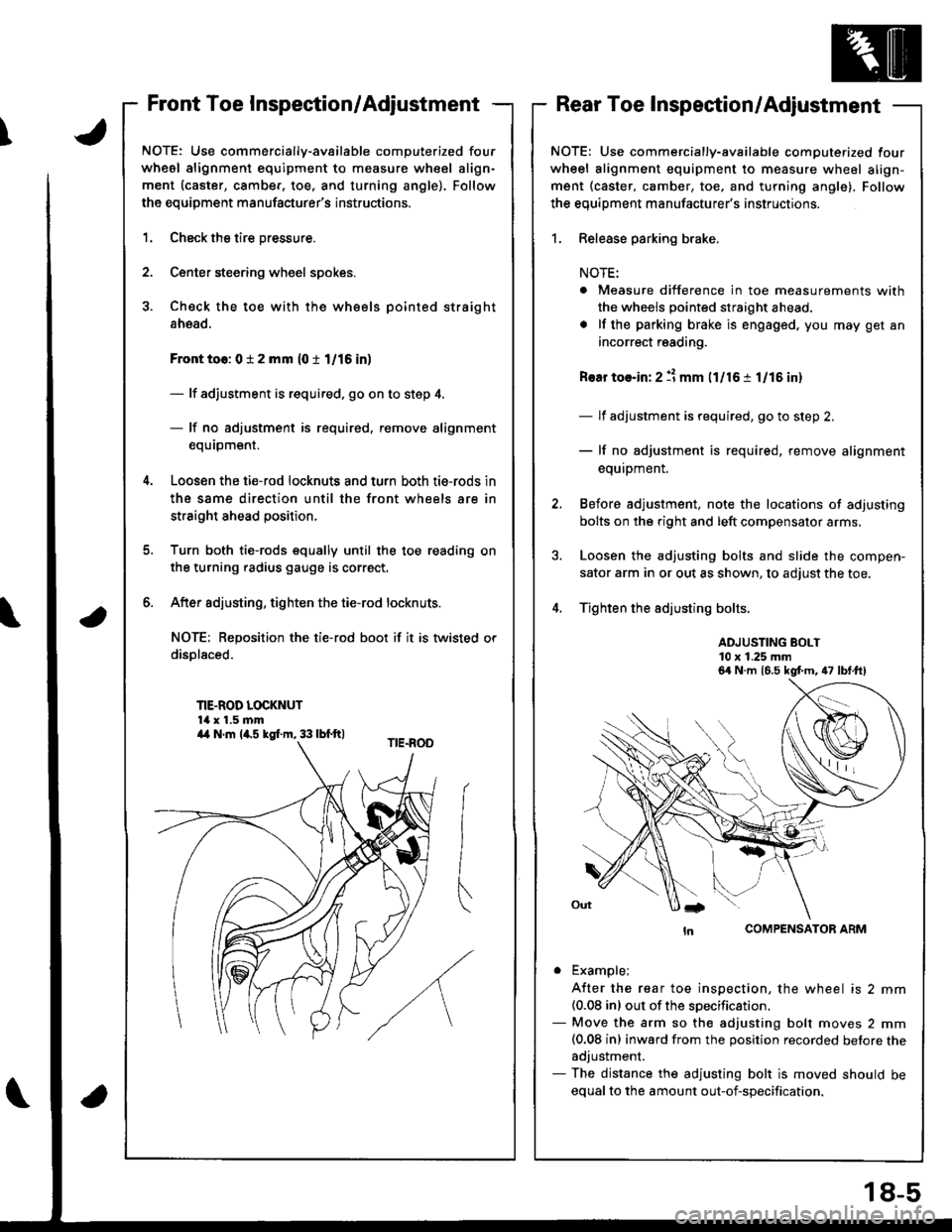
Loosen the adjusting bolts and slide the compen-
sator arm in or out as shown, to adjust the toe.
Tighten the adjusting bolts.
ADJUSTING BOLT10 x 1.25 mm
COMPENSATOR ARM
. Example;
A{ter the rear toe inspection, the wheel is 2 mm(0.08 inl out of the soecification.- Move the arm so the adjusting bolt moves 2 mm(0.08 inl inward from the position recorded betore theadjustment.- The distance the adjusting bolt is moved should be
equal to the amount out-of-specification.
6a N.m 16.5 kgt m, 47 lbt.ft)
a4 N.m la.s kgI.m, 33 lbf.ft)
18-5
Page 722 of 1681
Front Suspension
Knuckle/Hub (cont'd)
13.
N-ur--------------*i10 x 1.25 mm \
COTTERReplace.
NOTE: Use ball joint remover, 28 mm, to separate the
ball joints from the suspension or tie-rod end.
CAUTIONT Be careful not to damage the ball ioint boot.
Clean any dirt or grease off the ball joint.
Remove the cotter pin from the tie-rod end balljoint
castle nut, and remove the nut.
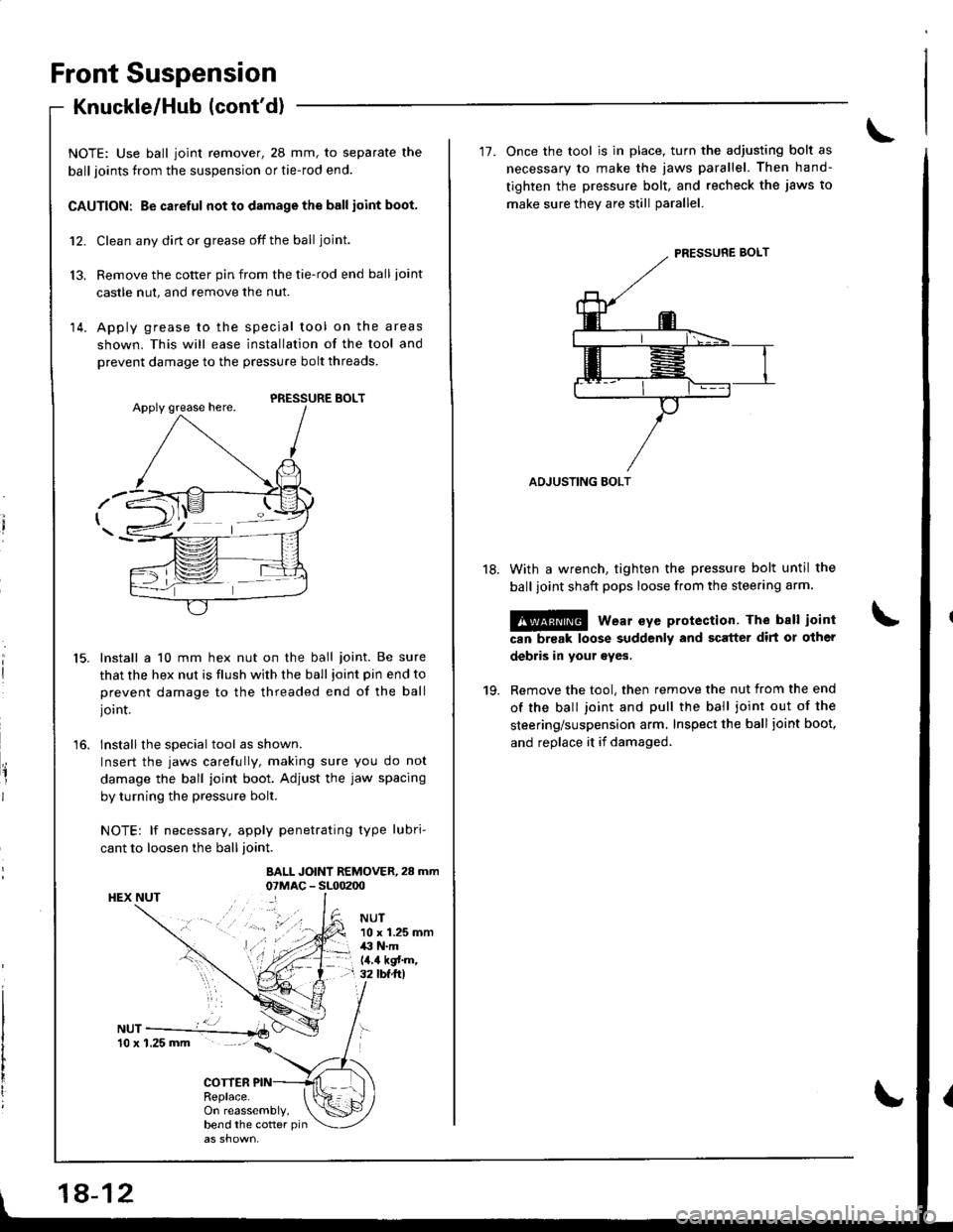
Apply grease to the special tool on the areas
shown. This will ease installation of the tool and
prevent damage to the pressure bolt threads.
12.
14.
15.
'16.
PRESSURE BOLT
Install a 10 mm hex nut on the ball joint. Be sure
that the hex nut is flush with the ball joint pin end to
prevent damage to the threaded end of the ball
joint.
Installthe special tool as shown.
Insert the jaws carefully, making sure you do not
damage the ball joint boot. Adjust the jaw spacing
by turning the pressure bolt.
NOTE: lf necessary, apply penetrating type lubri-
cant to loosen the ball joint.
BALL JOINT REMOVER,28 mm07MAC - SL00200HEX NUT
NUT10 x 1.25 mm,li' N.mla.a kgf'm,32 tbf ft)
On reassembly,bend the cotter pin
18-12
'17. Once the tool is in place, turn the adiusting bolt as
necessary to make the jaws parallel. Then hand-
tighten the pressure bolt, and recheck the jaws to
make sure thev are still oarallel.
ADJUSTING BOLT
With a wrench, tighten the pressure bolt until the
ball ioint shaft pops loose from the steering arm.
@ wear eye protection. The ball ioint
can break loose suddenly and scrtter dirt or other
debris in your eyes.
Remove the tool, then remove the nut from the end
of the ball joint and pull the ball ioint out of the
steering/suspension arm, Inspect the ball joint boot,
and replace it if damaged.
18.
19.
Page 726 of 1681
Front Suspension
Knuckle/Hub (cont'd)
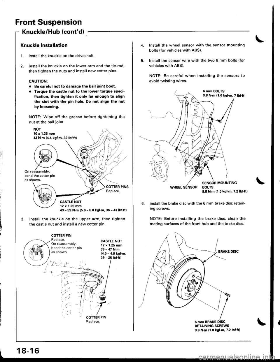
Knuckle lnstallation
1. lnstall the knuckle on the driveshaft.
2. lnstall the knuckle on the lower arm and the tie-rod,
then tighten the nuts and install new cotter pins.
CAUTION:
. Be carelul not to damage tho ball ioint boot.
a Torque the castls nut to the lowel torque spgci-
fication, then tight€n it only far enough to align
the slot with the pin hole. Do not align the nut
by loosening.
NOTE: Wipe off the grease before tightening the
nut at the ball joint.
NUT
ri
10 x 1.25 mm4il N.m (4.{ kgtm,32lbf.ftl
On reassembly,bend the cotter pin
as shown.
CASTLE NUT12 x 1 .25 mm49 - 59 N.m (5.0 - 6.0 kgf m, 36 -,|i| lbf ft)
3. Install the knuckle on the upper arm, then tighten
the castle nut and install a new cotter Din.
COTTER PINReplace.On reassembly,bend the cotter pin
CASTLE NUT12 x 1.25 mm39 - 47 N.m{4.0 - 4.8 kgf.m,29 - 3s rbr.ft)
;
, 'ar
COTTER PIN
18-16
4.Install the wheel sensor with the sensor mounting
bolts (tor vehicles with ABS).
lnstall the sensor wire with the two 5 mm bolts (for
vehicles with ABS).
NOTE: Be careful when installing the sensors to
avoid twisting wires.
6 mm BOLTS9.8 N.m 11.0 kgf.m,7 lbf.ftl
v_)
SENSOR MOUNTINGBOLTS9.8 N.m (1.0 kgf.m,7.2 lbl.ftl
6. lnstall the brake disc with the 6 mm brake disc retain-
Ing screws.
NOTE: Before installing the brake disc, clean the
mating surfaces of the front hub and the brake disc.
6 mm BRAKE DISCRETAINING SCREWS9.8 N.m 11.0 kgl.m, 7.2 lbf'ftl
Page 727 of 1681
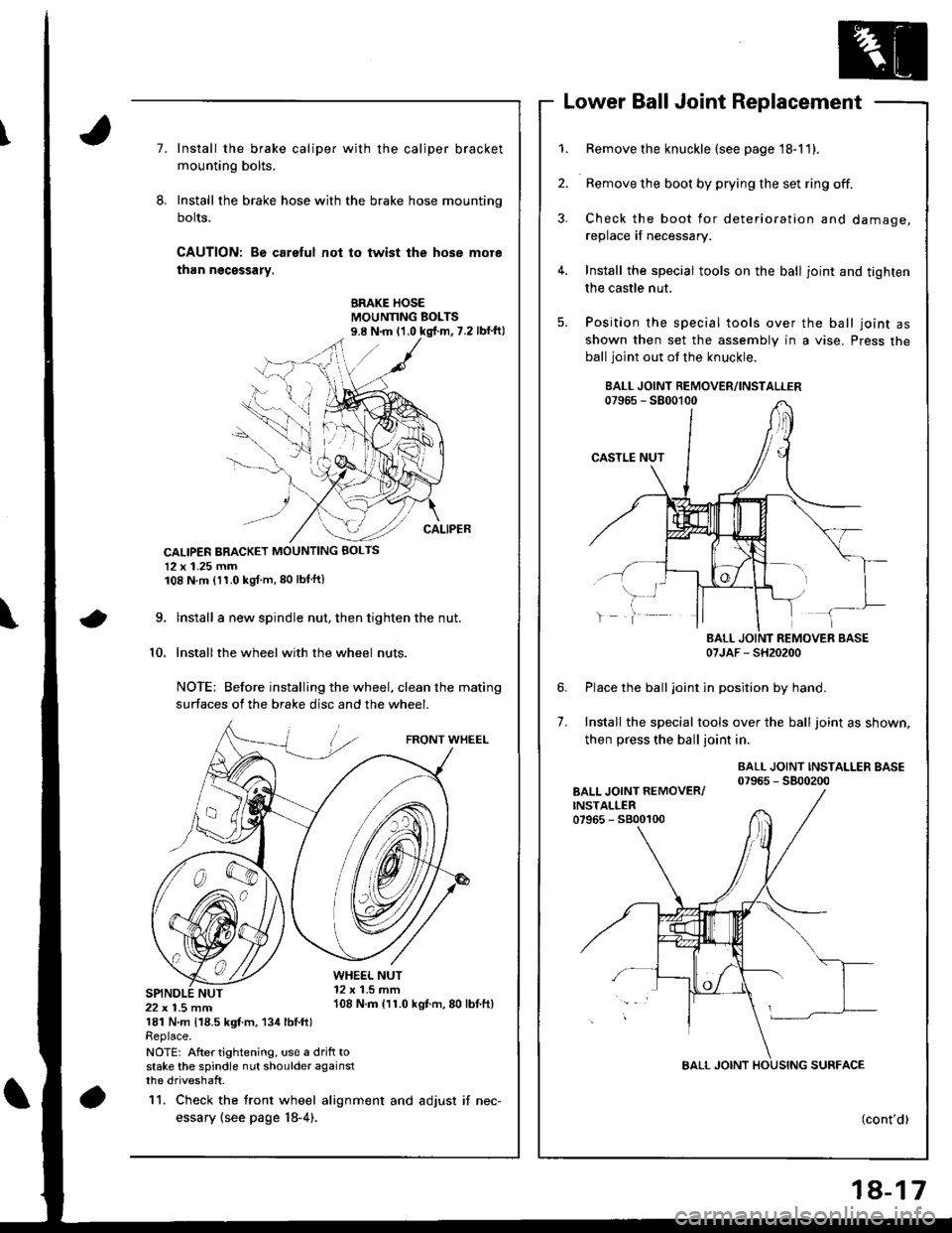
Lower Ball Joint Replacement
7.Install the brake caliper with the caliper bracket
mounting bolts.
Install the brake hose with the brake hose mounting
bolts.
CAUTION: Bo careful not to twist the hose more
than ngcsssary.
BRAKE HOSEMOUNNNG BOLTS
CALIPER BRACKET MOUNTING BOLTS
12 x 1.25 mm108 N.m (11.0 kgf m,80 lbtftl
\9.
10.
lnstall a new spindle nut, then tighten the nut.
Installthe wheel with the wheel nuts
NOTE: Before installing the wheel, clean the mating
surfaces of the brake disc and the wheel.
FRONT WHEEL
WHE€L NUT12 x 1.5 mm108 N.m {11.0 kgf.m,80 lbtft)22 x 1.5 mm181 N.m 118.5 kgt m, 134 lbl.ftlReplace.
NOTE: After tightening, us€ a drift tostake the spindle nut shoulder againstthe driveshaft.
11. Check the tront wheel alignment and adjust if nec-
essary (see page l8-4).
1.
2.
4.
5.
Remove the knuckle (see page 18-11).
Remove the boot by prying the set ring off.
Check the boot for deterioration and damage,
replace if necessary.
Install the special tools on the ball joint and tighten
the castle nut.
Position the special tools over the ball joint asshown then set the assembly in a vise. Press the
ball joint out of the knuckle.
07JAF - SH20200
Place the balljoint in position by hand.
Install the special tools over the ball joint as shown,
then press the ball joint in.
BALL JOINT INSTALLER BASE07965 - 5800200
6.
7.
(cont'd)
18-17
Page 728 of 1681
Front Suspension
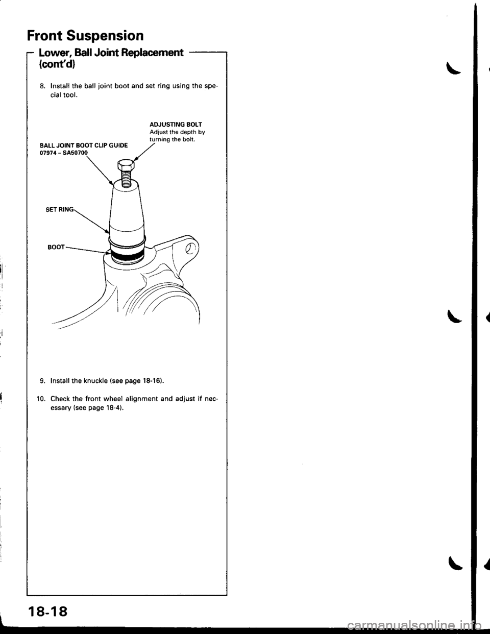
Lower, Ball Joint Replacement
(confd)
8. Install the ball joint boot and set ring using the spe-
cial tool.
9.
10.
Install the knuckle (see page 18-161.
Check the tront wheel alignment and adjust if nec-
essary (see page 18-4),
BALL JOINT BOOT CLIP GUIDE
18-18
Page 729 of 1681
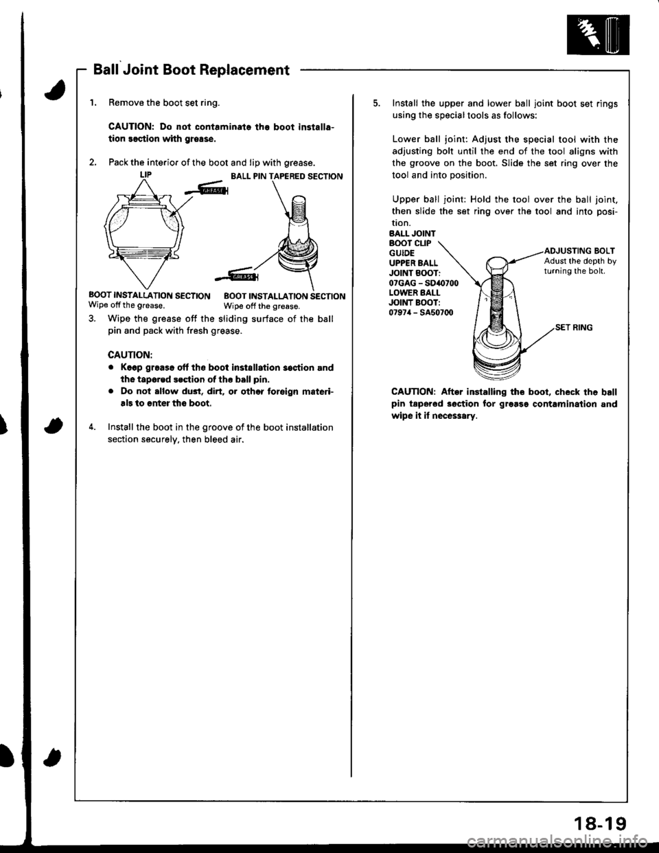
Ball Joint Boot Replacement
Remove the boot set ring.
CAUTION: Do not contaminata the boot installa-
tion seqtion with grease.
Pack the interio. of the boot and lip with grease.
BALL PIN TAPERED SECTION
BOOT INSTAI-LATION SECTION EOOT INSTALLATION SECTIONWipe offthe grease,Wipe off the greaso.
3. Wipe the grease off the sliding surface of the ball
pin and pack with fresh grease.
CAUTION:
o Keep grease olf ths boot instsllation 3ostion and
the tapored $ction ot ths ball pin.
. Do not sllow du3t, dirt. or othor foreign materi-
als to €nter tho boot.
4. Install the boot in the groove of the boot installation
section securelv, then bleed air.
Install the upper and lower ball joint boot set rings
using the specialtools as follows:
Lower ball joint: Adjust the special tool with the
adjusting bolt until the end of the tool aligns with
the groove on the boot, Slide the set ring over the
tool and into position.
Upper ball joint: Hold the tool over the ball joint.
then slide the set ring over the tool and into posi-
tron.BALL JOINTBOOT CLIPGUIDEUPPER BALLJOINT BOOTio?GAG - SD4(,700LOWER EALLJOINT BOOT:0797/r - SA507q)
BOLTAdlst the depth byturning the boh.
CAUnON: Aftor installing the booi, check the ballpin tspersd 3oction tor gr9as9 contaminaiion and
wipe it if nece$ary.
18-19
Page 730 of 1681
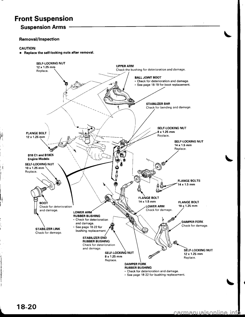
Front Suspension
Removal/lnspection
CAUTION:
. Replacs ihe self-locking nuts after r6moval'
SELF-LOCKING NUT12 x 'l.25 mmReplace.
UPPER ARMCheck the bushing for deterioration and damage.
Suspension Arms
818 Cl and B18C5
Engin6 Mod.ls:
SELF.LOCKING NUT10 x 1.25 mmReplace.
BALL JOINT BOOT. Check for deterioration and damage.' See page 18 19 for boot replacement.
STABILIZER BARCheck for bending and damage.
SELF-LOCKING NUTx 1-25 mmReolace,
14 x 1.5 mm
SELF.LOCKING NUT14 x 1.5 mmReplace.
FLANGE BOLTS14 x l.5 mm
FLANGE BOLT10 x 1.25 mmCheck for deteriorationano oamage,LOWER ARMCheck for damage.LOWER ARMRUBBER BUSHING. Check for deteriorationano oamage.. See page 18-22 tor
OAMPER FORKCheck for damage
bushing replacement.
and damage.
STABILIZER ENDRUBBER BUSHINGCheck f or deterioration
-LOCKING NUT12 x 1.25 mmReplace.
OAMPER FORKRUBBER BUSHING. Check for deterioration and damage.. See page 18 22 for bushing replacement.
STABILIZER LINK
1A-20
Page 748 of 1681
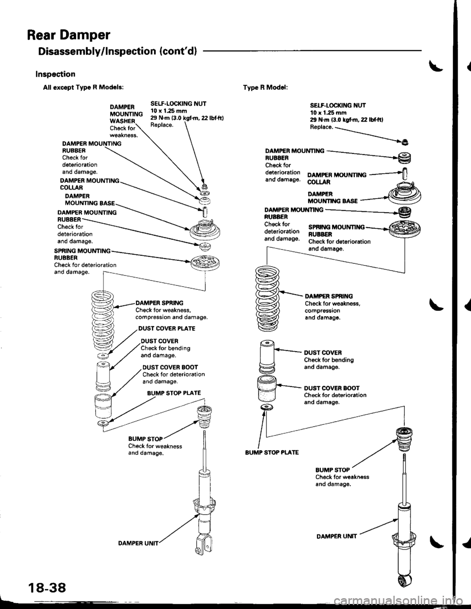
Rear Damper
Disassembly/lnspection {cont'd}
Inspestion
All oxcspt Typo R Models:
DAMPERMOUNTING
Check for
Check Ior weaknessand damag6.
DAMPERRUEBERCheck ford€t6riorationano damage.
DAMPER MOUNTINGCOLLAR
DAMPER
SELF.LOCKING NUT10 x 1.25 mm29 N.m 13.0 kgf.m, 22 lbt'ft)R6place.
Type R Model:
BUMP STOP PLATE
SELF-LOCKING NUTt0 r 1.25 mm29 N.m (3.o kgt m, 22 lbf'ft)Rep|aco. -.\-.--...\
_____6
DAMPTRMoUNnNG -.-__re
Check fordeterioration DAMPERMOUNnNG -----+,and damag6. @L!AR Ag-
liillffi*"*,--@
DAMPTR MoU.{nNG __-_____*e
DUST COVEBCh6ck for b€ndingand oamage.
DUST OOVER BOOTCh€ck for deterioralionand damage.
MOUNNNG BASE
DAMPEB MOUNTINGRUBBERCheck lordeteriorationano oamage.
SPRING MOUNTINGRUBBERCheck for deteriorationano oamage.
Check for weakness,compression and damage.
DUST COVER PLAT€
DUST COVERCheck for bendingano oamage.
DUST COVER BOOTChock for deteriorationano oamage,
AUMP STOP PLAYE
1€')
I t_--tlg:z
q._
Y
Check for weaknessand damage.
BUMP STOP
18-38
DAMPER UNTTDAMPER UN]T