boot HONDA INTEGRA 1998 4.G Workshop Manual
[x] Cancel search | Manufacturer: HONDA, Model Year: 1998, Model line: INTEGRA, Model: HONDA INTEGRA 1998 4.GPages: 1681, PDF Size: 54.22 MB
Page 363 of 1681
T
fi
;ill
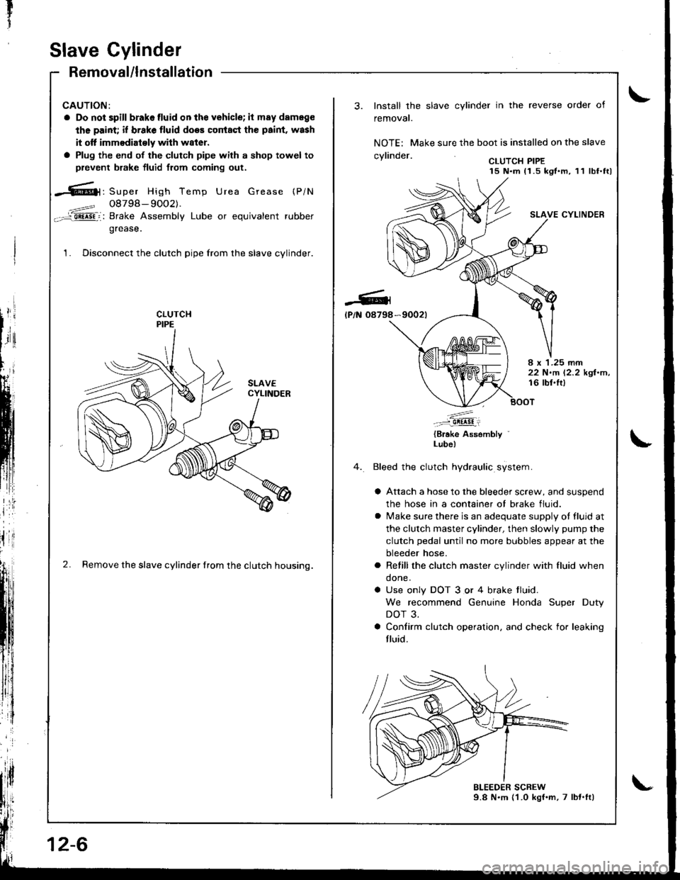
Slave Cylinder
Removal/lnstallation
CAUTION:
a Do not spill brakelluid onthe vehicle; it may dameg€
the paint; if brake fluid does coniaqt the paint, wash
it otf immodiaioly wilh w8ter.
a Plug the end of the clutch pipe with a shop towel to
prevent brake fluid from coming out.
-6|1, Super High Temp Urea Grease (P/N
4==? 08798- 9OO2).-='aii^5Fi: Brake Assembly Lube or equivalent rubber
grease.
1. Disconnect the clutch pipe from the slave cylinder.
2. Remove the slave cylinder from the clutch housing.
12-6
-Gl
lP/N 08798
Install the slave cylinder in the reverse order of
removal.
NOTE: Make sure the boot is installed on the slave
.wlin.larCLUTCH PIPE15 N.m 11.5 kgt.m, 11 lbf.ttl
SLAVE CYLINDER
*9002t
I x 1.25 rnm22 N.m 12.2 kgl.m,16 lbl.lt)
.'....-..-:::-9!!!!!i
{Brake Assembly '
Lube)
Bleed the clutch hydraulic system.
a Attach a hose to the bleeder screw, and suspend
the hose in a container ot brake fluid.
a lvlake sure there is an adequate supply ot fluid at
the clutch master cylinder, then slowly pump the
clutch pedal until no more bubbles appear at the
bleeder hose.
a Refill the clutch master cylinder with fluid when
done.
a Use only DOT 3 or 4 brake tluid.
We recommend Genuine Honda Super Duty
DOT 3.
a Confirm clutch operation. and check for leaking
fluid.
Page 368 of 1681
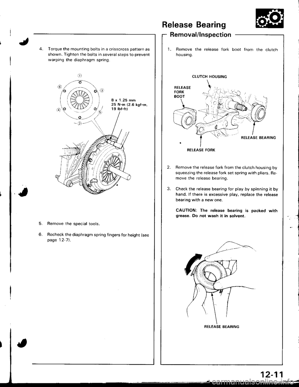
Release Bearing
Removal/lnspection
1. Remove the release fork
housrng.
boot from the clutch
5.
6.
Torque the mounting bolts in a crisscross pattern as
shown. Tighten the bolts in several steps to prevent
warping the diaphragm spring.
8 x 1.25 mm25 N.m {2.6 kgf.m,19 tb{.fr}
Remove the special tools.
Recheck the diaphragm spring fingers for height {seepage 12-7).
CLUTCH HOUSING
BELEASE AEAFING
RELEASE FORK
Remove the release fork from the clutch housing by
squeezing the release fork set spring with pliers. Re
move the release bearing.
Check the release bearing for play by spinning it by
hand. lf there is excessive play, replace the release
bearing with a new one.
CAUTION: The release bearing is packed wirhgrease. Do not wash it in solvent.
a;;;:
S",€ r
K4IN/
RELEASE BEARING
Page 369 of 1681
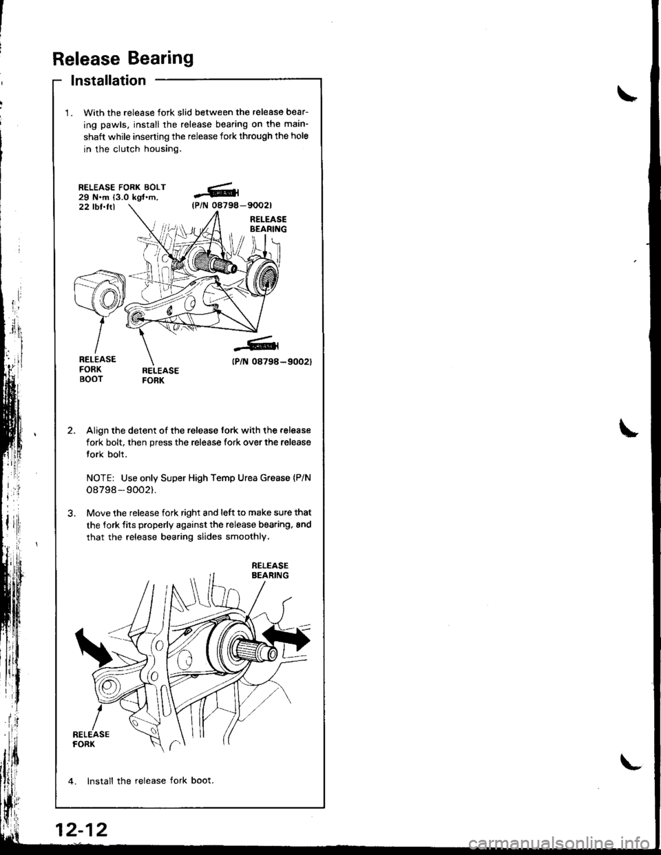
Release Bearing
lnstallation
With the release fork slid between the release bear-
ing pawls, install the release bearing on tha main-
shaft while inserting the release fork through the hole
in the clutch housing.
RELEASE FORK BOLT29 N.m (3.0 kgl.m,22 tbt.ttl
Align the detent of the release fork with the release
fork bolt, then press the release fork over the release
fork bolt.
NOTE: Use only Super High Temp Urea Grease {P/N
o8798 - 9002).
Move the release fork right and l6ft to make sute that
the fork fits properly against the release bearing, 8nd
that the release bearing slides smoothly.
4. lnstall the release fork boot.
-6(P/N 08794-
-6
tPlN 08798-
RELEASE
12-12
Page 384 of 1681
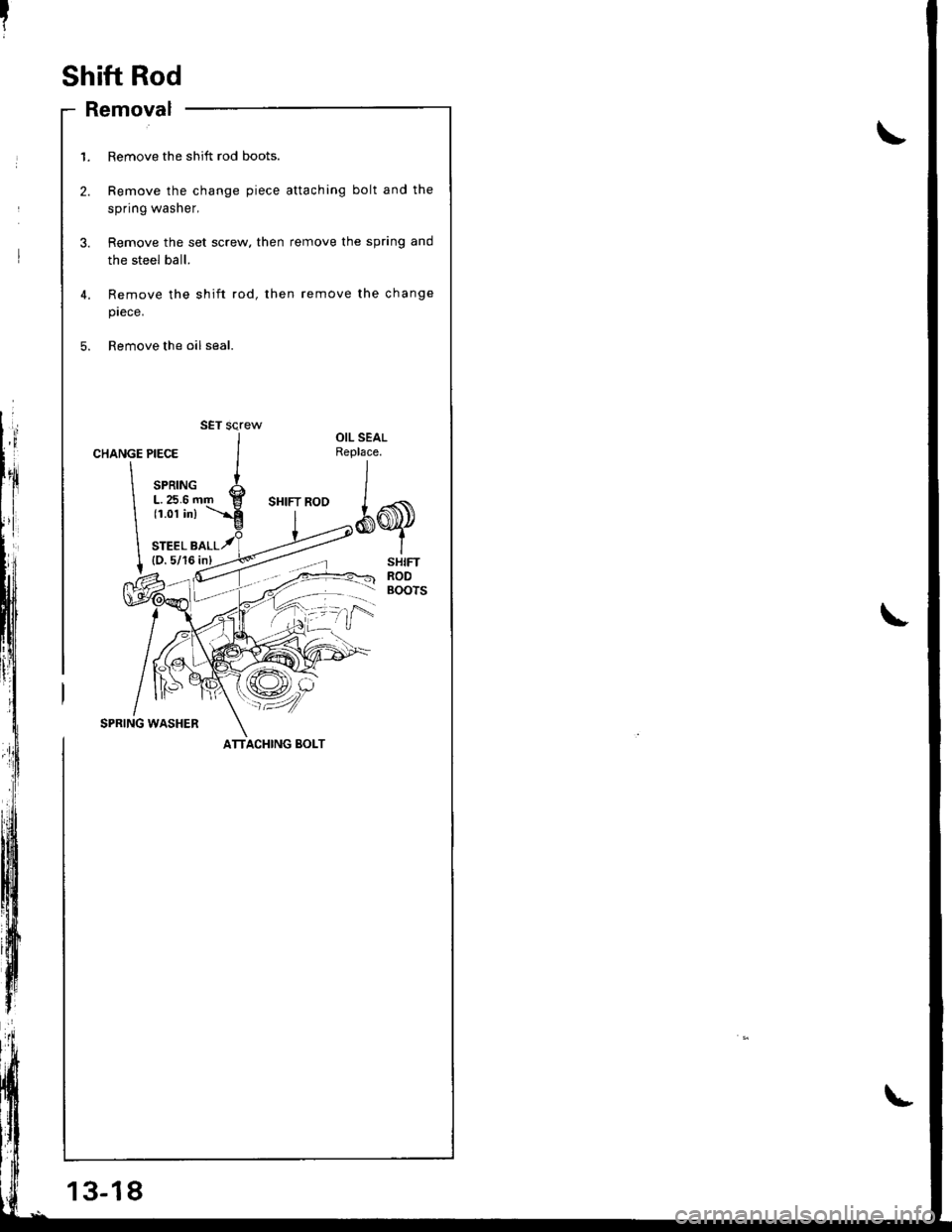
Shift Rod
- Removal
13-18
1. Remove the shift rod boots.
2. Remove the change piece attaching bolt and the
spring washer,
3. Remove the set screw. then remove the spring and
the steel ball.
4,
5.
Remove the shift rod, then remove the change
prece.
Remove the oil seal.
CHANGE
\
\
I
PIECE
SPRINGL.25.6 r(1.01 in)
STEEL B(D.5/16
OIL SEALReplace.
*q
SHIFTRODBOOTS
SPRING WASHER
SET screw
ATTACHING BOLT
Page 407 of 1681
I
t
\
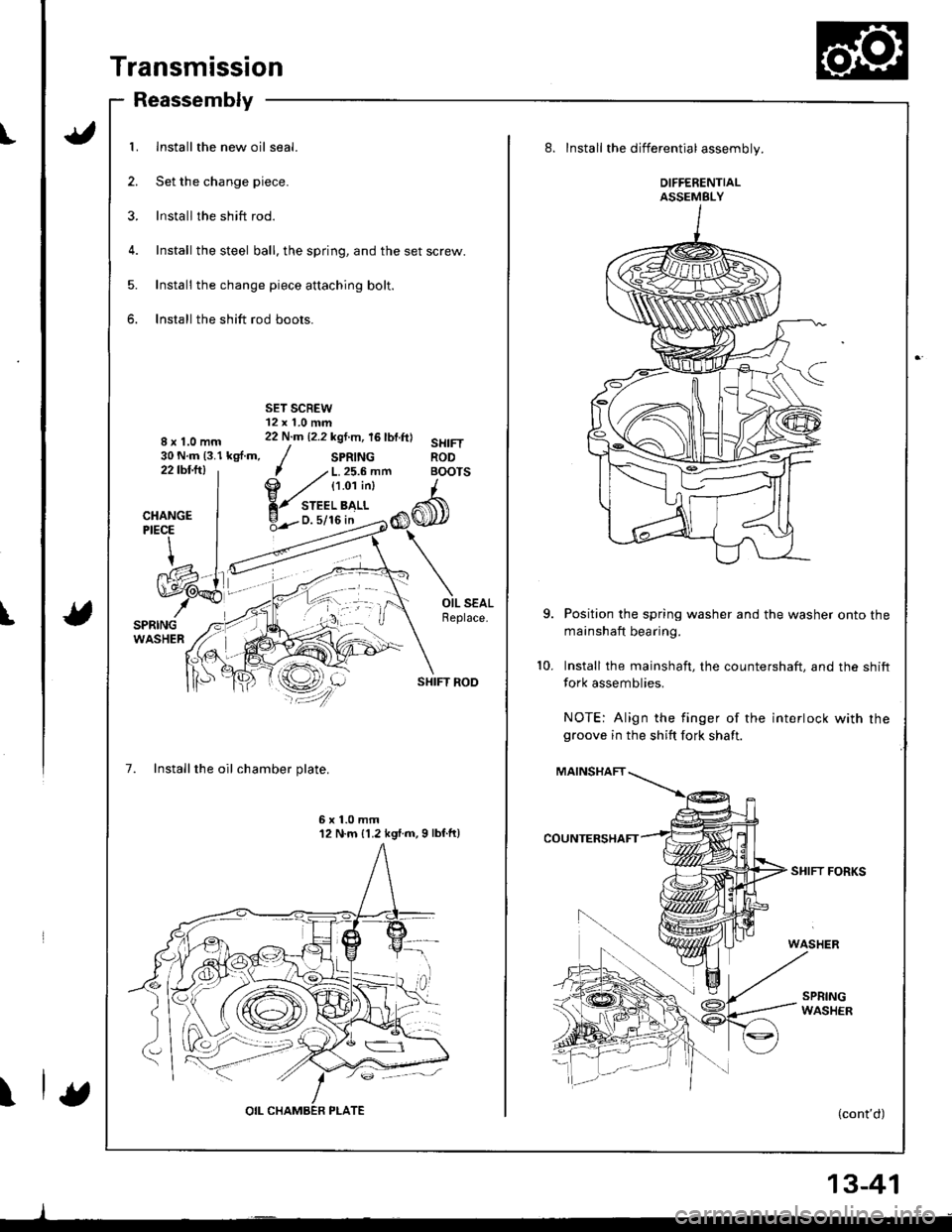
Transmission
Reassembly
1. Install the new oil seal.
2. Set the change piece.
3. lnstall the shift rod.
4. Install the steel ball, the spring, and the set screw.
5. Install the change piece attaching bolt.
6. Install the shift rod boots.
8x1.0mm30 N.m (3.1 kgf.m,22tbfitl
SHIFT ROD
7. Installthe oil chamber plate.
7 .' L. 25.6 mfi BOI
@ ,zt tt.o'ti"t I
Y-",:'b>,",CI
6x1.0mm12 N.m {1.2 kgl.m,9 lbf.ft)
8. Install the differential assembly.
DIFFERENTIALASSEMBLY
Position the spring washer and the washer onto the
mainshaft bearing.
Install the mainshaft, the countershaft. and the shift
fork assemblies.
NOTE: Align the finger of the interlock with rhegroove in the shift fork shaft.
MAINSHAFT
SHIFT FORKS
(cont'd)
10.
13-41
Page 412 of 1681
I
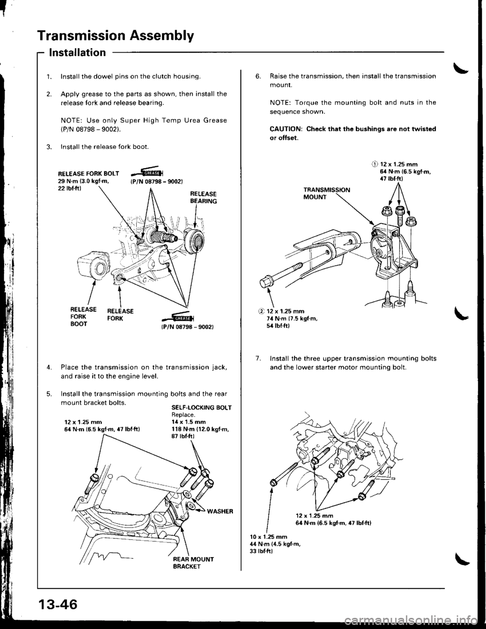
Transmission Assembly
1.
2.
Install the dowel pins on the clutch housing.
Apply grease to the parts as shown, then install the
release fork and release bearing.
NOTE: Use only Super High Temp Urea Grease
(P/N 08798 - 9002).
3. Install the release fork boot.
lnstallation
22 tbl.lll
RELEASE FORK BOLT29 N.m {3.0 kgl.m,{P/N 08798 - 9002t
RELEASEBEAFING
RELEASEFORK
lPlN 08798 - 90021
Place the transmission on the transmission jack,
and raise it to the engine level.
Install the transmission mounting bolts and the rear
mount bracket bolts.SELF.LOCKING BOLT
12 x 1.25 mm64 N.m {6.5 kgf.m, {7 lbtftl
Replace.14 x 1.5 mm
RELEASEFORKBOOT
\i'l-r )i-
.+.i
13-46
6. Raise the transmission, then install the transmission
mounr,
NOTE: Torque the mounting bolt and nuts in the
sequence shown.
CAUTION: Check that the bushings are not twisted
or offset.
!) tz x t.zs mm64 N.m {6.5 kgt.m,47 tbl.ftl
7. Install the three upper transmission mounting
and the lower staner motor mountinq bolt.
bolts
10 x 1.25 mm44 N.m (4.5 kgt m.33 tblftl
(a 12 x 1.25 mm74 N.m {7.5 kgf m,54 tbf.ft)
'12x1.25m�n
64 N.m {6.5 kst.m,47 lbf,ft)
Page 414 of 1681
[!
"
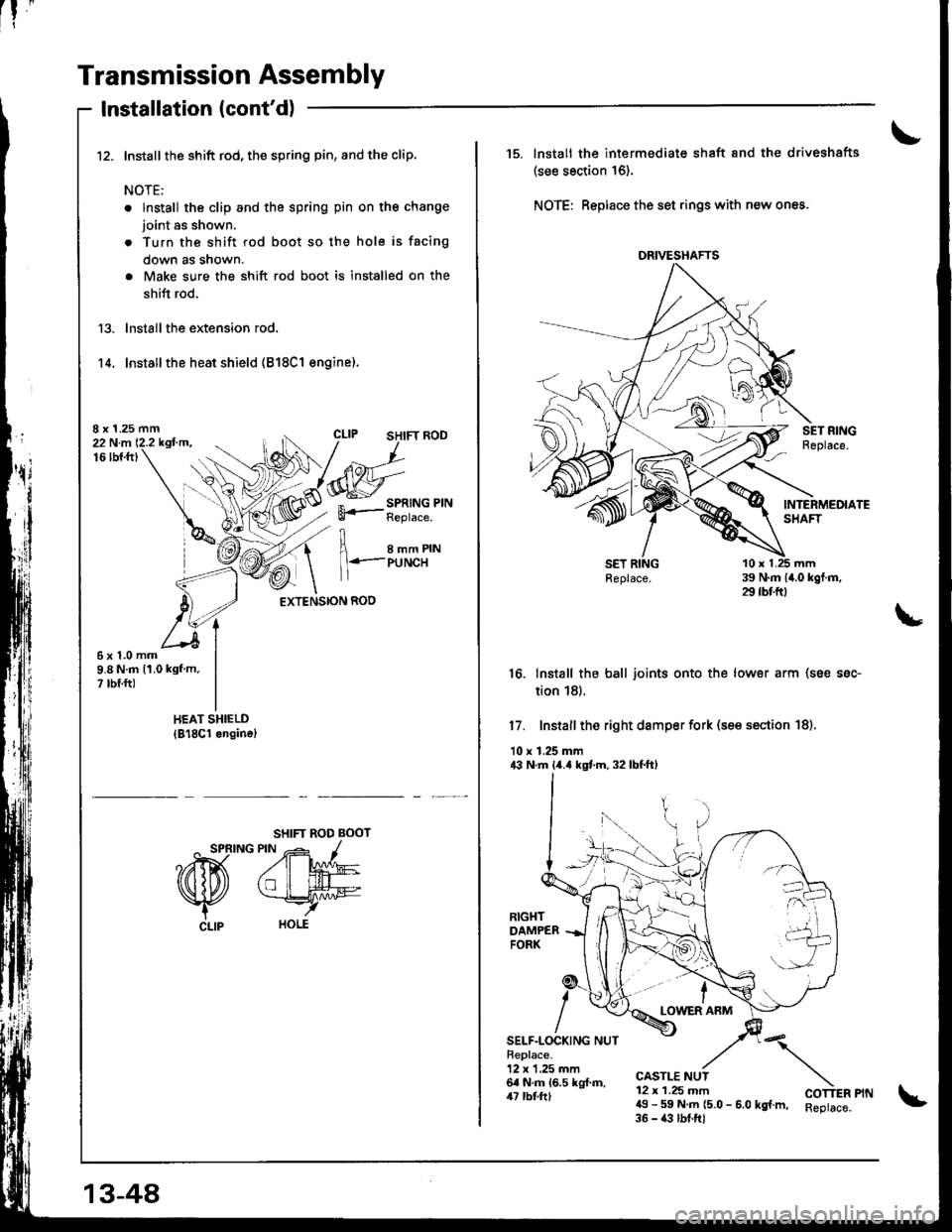
Transmission Assembly
Installation (cont'd)
Install the shift rod, the spring pin, and the clip.
NOTE:
. lnstall the clip and the spring pin on the change
joint as shown.
. Turn the shift rod boot so the hole is facing
down as snown.
. Make sure the shift rod boot is installed on the
shift rod.
lnstall the extension rod.
Installthe heat shield (818C1 engine).'t 4.
8 x 1.25 mm22 N.m 12.2 kgfm.16lbt.ft)
I e--erru
1 l+.-PUNCH
EXTENSION ROD
6x1.0mm9.8 N.m 11.0 kgf m,? rbf.ft)
SHIFT ROD BOOT
^ SPRING PIN -- -1
?ffi A'W
Nfu *rry
CLlp HOLE
13-48
DRIVESHAFTS
15. lnstall the intermediate shaft 8nd the driveshafts
(see section 16).
NOTE: Beplace the set rings with new ones.
16. Install the ball joints onto the lower arm (soe ssc-
tion 18).
17. Install the right damper fork (see ssction 18).
10 r 1.25 mm43 N.m lir.a kgt m. 32 lbtftl
LOWER ARM
SELF.LOCKING NUTReplace.12 x 1,25 mm6a N.m 16.5 kg{.ft,/u rbl.tt)
CASTLE NUT12 x 1.25 mm49 - 59 N.m (5.0 - 6.0 kgf.m, Reptace.35 - 43 lbf.ftl
"\
COTTER PIN
Page 417 of 1681
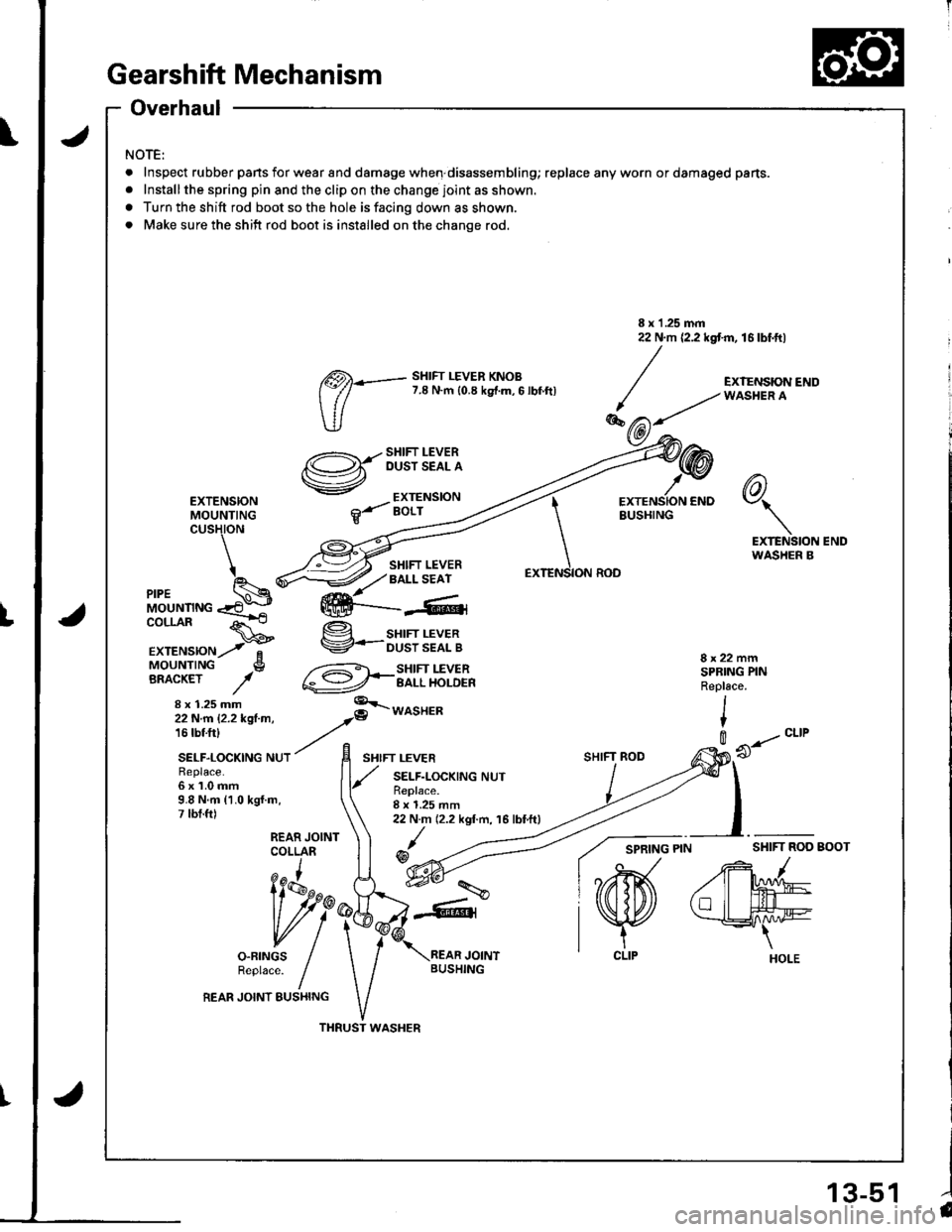
Gearshift Mechanism
Overhaul
NOTE:
.Inspe(
.lnstall
a Turn t
. Make
Inspect rubber pans for wear and damage when disassembling; replace any worn or damaged pans.
Installthe spring pin and the clip on the change joint as shown.
Turn the shift rod boot so the hole is facing down as shown.
Make sure the shift rod boot is installed on the change rod.
\
tu
<:;s\-
-,-"Ye/
R€place.6x1.0mm9.8 N.m {1.0 kgl.m,7 lbt.ft)
liAru^
vll
o-FTNGS /Reptace. fREAR JOINT EUSHING
I x 1 .25 mm22 N.m {2.2 kgt m, 16 lbf.ft)
EXTENSIONMOUNTINGcusHtoN
6)\7\
EXTENSION ENDWASHER B
MOUNTINGCOLLAR
EXTENSIONMOUNTINGBRACKET
x 1.25 mm
SHIFT LEVERBALL SEAT
g sHrFr LEVERV-ousrssflg
@*3li.T'lib'l'
8x22mmSPBING PINRepl6ce.
I
t
SHIFT ROD
0 --..- "ttt
REAR JOINTCOLLARSHIFI ROD BOOT/
/rM
tllL#e
THRUST WASHER
@)*- sHtFr LEVER KNoB
(:// 7.8 N.m {0.8 ks{.m,6 lbf.ftl
SHIFT LEVEROUST SEAL A
EXTENSIONBOLT
8 x 1.25 mm22 N.m (2.2 kgf.m, 16 lbtft)
/@
EXTENSION CNDBUSHING
ION ROD
-\
\
\EXTENS
ffi---4,
l'a13-51
Page 634 of 1681
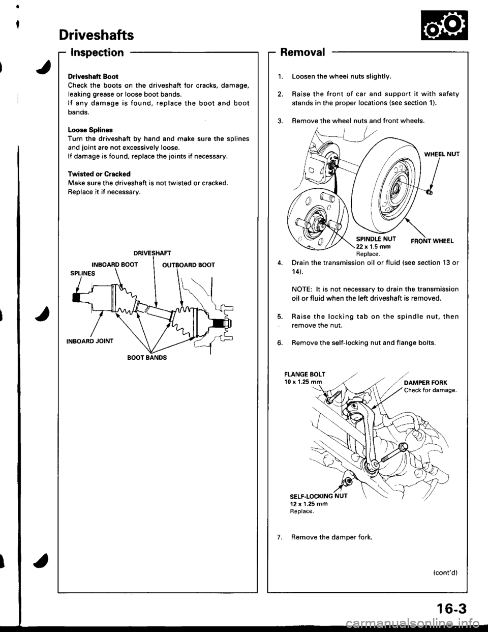
t
Driveshafts
Inspection
Drivcshatt Boot
Check the boots on the driveshaft tor cracks. damage,
leaking grease or loose boot bands.
lf any damage is found, replace the boot and boot
oanos.
Looso SplineE
Turn the driveshaft by hand and moke sure the splines
and joint are not excessively loose.
lf damage is found, replace the joints if necessary.
Twisled or Crscked
Make sure the driveshaft is not tlvisted or cracked.
Replace it if necessary.
BOOT BANDS
1.Loosen the wheel nuts slightly,
Raise the front of ca. and support it with safety
stands in the prope. locations {see section 1).
Remove the wheel nuts and front wheels.
5.
Drain the transmission oil or fluid (see section 13 or
14t.
NOTE: lt is not necessary to drain the transmission
oil or fluid when the left driveshaft is removed.
Raise the locking tab on the spindle nut, then
remove the nut.
6. Remove the self-locking nut and flange bolts.
FLANGE BOLT'10 x 1.25
SELF.LOCKING NUT
12 x 1.25 mmReplace.
(cont'd)
Replace.
7. Remove the damoer fork.
Removal
6-3
Page 635 of 1681
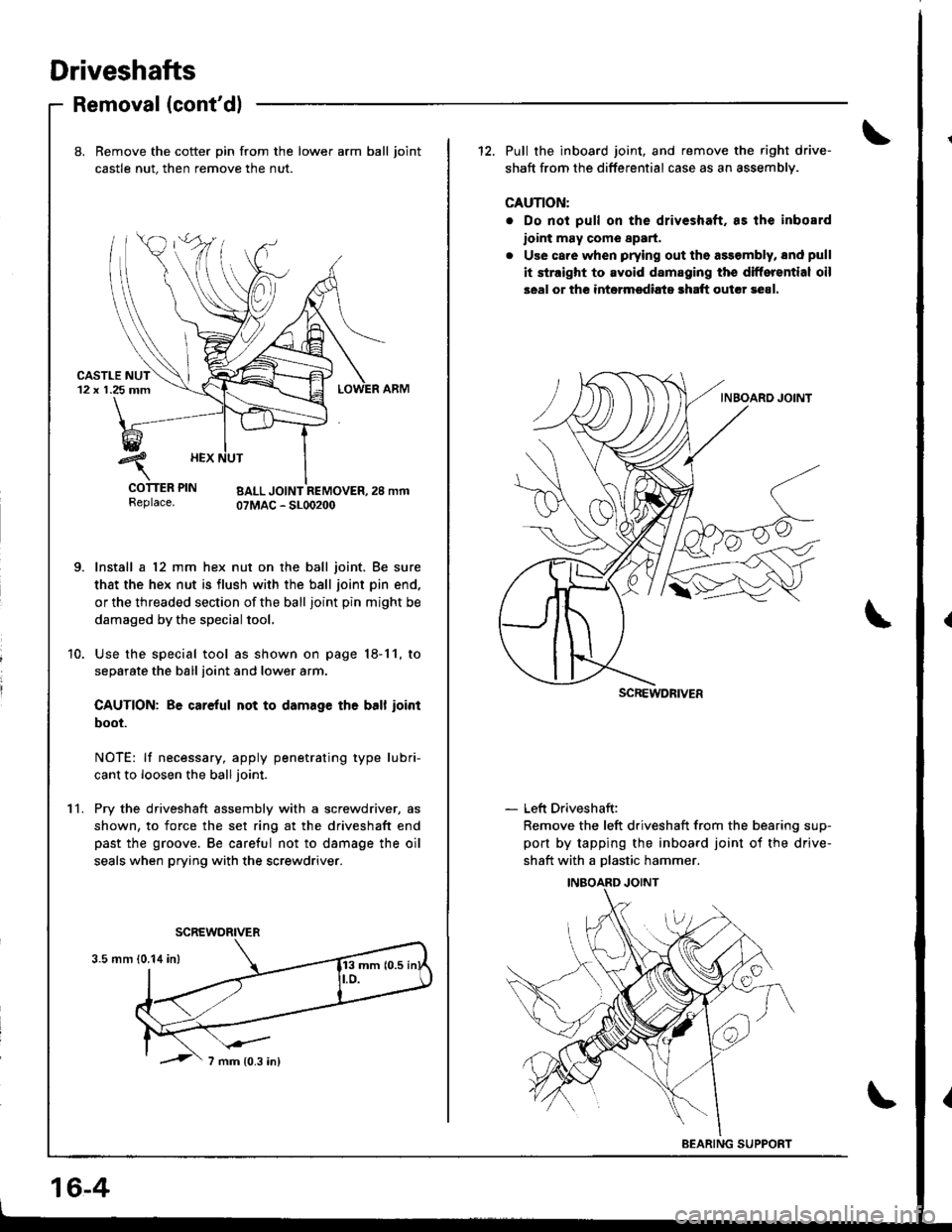
Driveshafts
Removal (cont'dl
11.
8. Bemove the cotter pin from the lower arm ball joint
castle nut. then remove the nut.
urJr rEr rrN BALL JOINT REMOVER,2S mmReplace. OTMAC - SLOO2OO
Install a 12 mm hex nut on the ball joint. Be sure
that the hex nut is flush with the ball joint pin end.
or the threaded section of the ball joint pin might be
damaged by the special tool.
Use the special tool as shown on page 18-11, to
separate the ball ioint and lower arm.
CAUTION: Be careful not to damage th6 ball ioint
boot.
NOTE: lf necessary, apply penetrating type lubri-
cant to loosen the ball joint.
Pry the driveshaft assembly with a screwdriver, as
shown, to force the set ring at the driveshaft end
past the groove. Be careful not to damage the oil
seals when prying with the screwdriver.
12. Pull the inboard joint, and remove the right drive-
shaft from the differential case as an assemblv.
CAUTION:
. Do not pull on the driveshaft. as lhe inbosrd
ioint may come 8p8rt.
. Use care when prying out the assembly, snd pull
it straight to avoid damaging the differential oil
seal or the intermsdiats rhaft outcr 3e81.
- Left Driveshaft:
Remove the left driveshaft from the bearing sup-
port by tapping the inboard joint of the drive-
shaft with a Dlastic hammer.
SCREWDRIVER
BEARING SUPPORT
16-4