boot HONDA INTEGRA 1998 4.G Owner's Manual
[x] Cancel search | Manufacturer: HONDA, Model Year: 1998, Model line: INTEGRA, Model: HONDA INTEGRA 1998 4.GPages: 1681, PDF Size: 54.22 MB
Page 651 of 1681
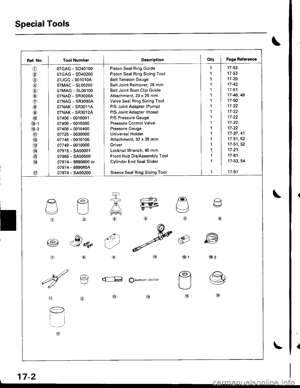
SpecialTools
{
\
\
17-2
Ref. No. I Tool NumberDsscriptionOty I Pags Reterenc.
o
@
@
o
@
@
@
@
@
@-1
@-2
o6:^
@
@
@
@
@
07GAG - SD40100
07GAG - SD40200
07JGG - 001010A
07MAC - S100200
07MAG - S100100
07NAD - SR3020A
OTNAG _ SR3OgOA
OTNAK - SR3O11A
OTNAK - SR3O12A
07406 - 0010001
07406 - 0010300
07406 - 0010400
07725 - 0030000
07746 - 0010100
07749 - 0010000
07916 - SA50001
07965 - SA50500
07974 - 6890800 or
07974 - 6890804
07974 - SA50200
Piston Seal Ring Guide
Piston Seal Ring Sizing Tool
Belt Tension Gauge
Ball Joint Remover, 28 mm
Ball Joint Boot Clip Guide
Attachment, 23 x 25 mm
Valve Seal Ring Sizing Tool
P/S Joint Adapter (Pump)
P/S Joint Adapter (Hose)
P/S Pressure Gauge
Pressure Control Valve
Pressure Gauge
Universal Holder
Attachment, 32 x 35 mm
Driver
Locknut Wrench. 40 mm
Front Hub Dis/Assembly Tool
Cylinder End Seal Slider
Sleeve Seal Ring Sizing Tool
'I
1
1
1
1'|
1,l
I
1
1
1'I
'l
1
1
1
1
1
't7-53
17-53't]-20
11-42
17 -51
17 -46, 4A
17-50
17-37, 41
11-51,52't1-51,52
17 -2'�1
17 -6'l
17-53. 54
17-51
o
L'4,
o
€)
-g)c-J 8p
@
@
6i
(9')\E/'
@-t
a
6
ffi
@-z
d--E ia*=-
o
l-l
t..-_-.r
A)
@@@
\
Page 652 of 1681
I
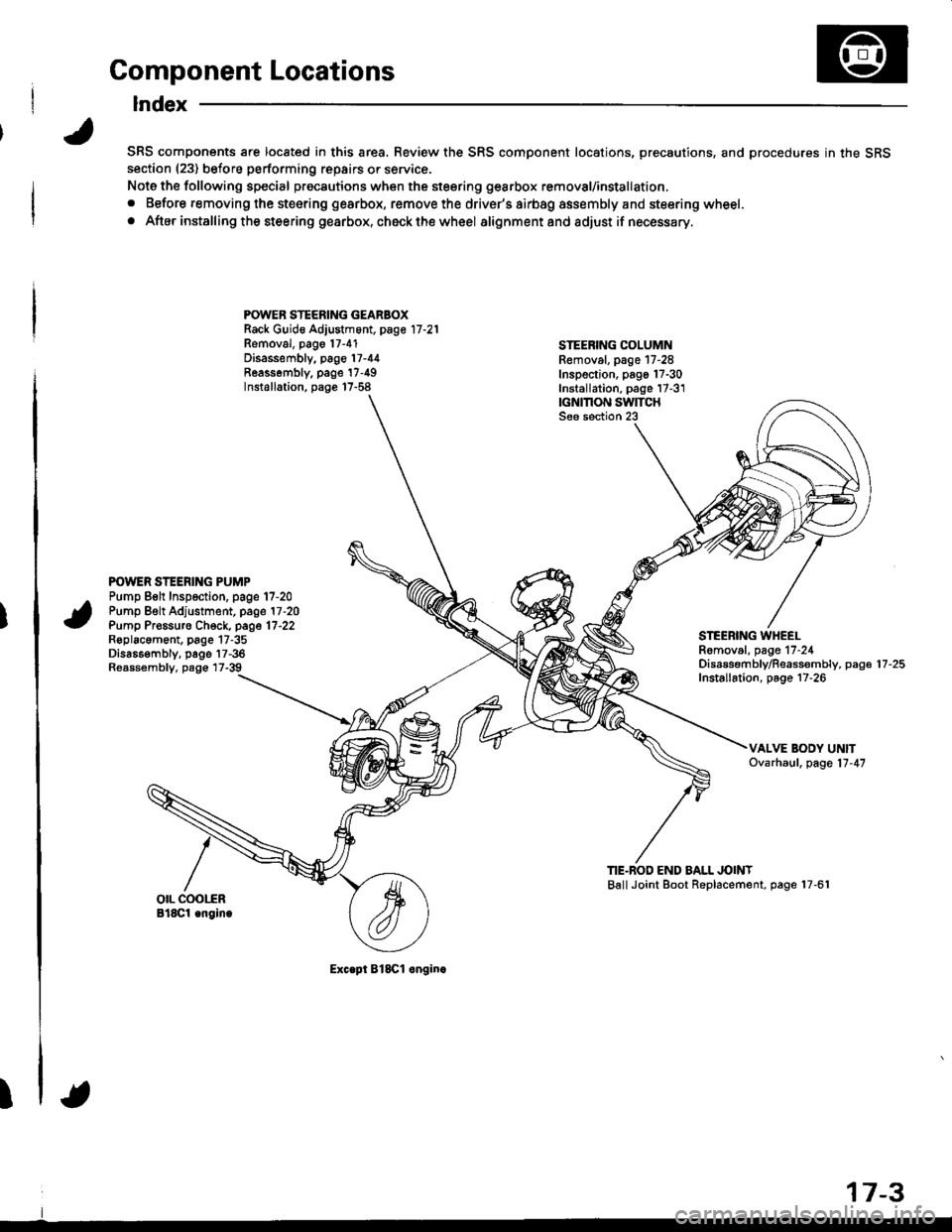
Component Locations
Index
SRS components are located in this area. Review the SRS component locations, precautions, and procedures in the SRSsection (23) before performing repairs or service.
Note the following special precautions when the steering gearbox removal/installation,
. Before removing the steering gearbox, remove the driver's airbag assembly and steering wheel.
. After installing the steering gearbox, ch6ck the wheel alignmentand adjust if necessary.
POWER STEERING GEARBOXRack Guid€ Adjustment, page 17 -21
Removal, pago 17-4'1Disassembly, page 17-44Reassombly. page'17-49Installation, page 17-58
STEEBING COLUMNRemoval. page 17-28Inspection, pago 17-30Installation, page 17-3'1|GNMON SWITCHSee section 23
POWER STEERING PUMPPump Belt Inspection. page 17-20Pump Belt Adjustment, page 17 -20
Pump Pr€ssuro Check, page 17'22Roplacament, page 17-35Dis686embly, page 17-36Reassembly, page 17-39
STEEBING WHEELRomoval, page 17-24Disassembf y/Reassembly, paga 17 -25
Installation, page 17-26
TIE.BOD END BALL JOINTBallJoint Boot Replacement, page 17-61
Exc.pt BlSCl onginc
17-3
Page 665 of 1681
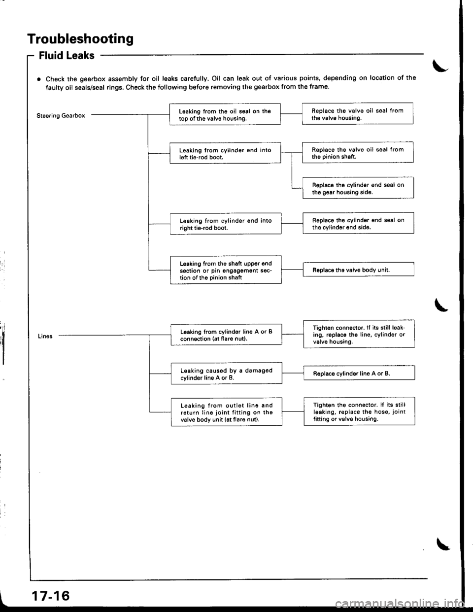
Troubleshooting
Fluid Leaks
Check the gearbox assembly for oil leaks carefully, Oil can leak out of various points, depending on location of the
faulty oil seals/seal rings. Check the following before removing the gearbox from the frame.
Stoo.ing GearboxReplace the valv€ oil seal fromthe valvo houging.Leaking from the oil seal on thetop of the valve housing.
Roplace the valve oil seal fromthe pinion shaft.Leaking trom cylinder 6nd intol€ft ti6-rod boot,
B€place tho cylindgr ond seal onthe gear housing side.
Replaco th€ cylindor end seal onths cylinder end side.Leaking from cylinder end intoright tie-rod boot.
Leaking from the thaft upper endsection or pin ongagement sgc-tion ofth6 Dinion shaftRoDlace tho valve bodv unit.I
I
Tighten connector. lf it€ still leak-ing. replace th€ lin€, cylinder orvalve housing.
Leaking lrom cylind6r line A or Bconn6ction {Et flare nut).
Leaking caused by a damagedcylinder line A or B.Replace cylinder line A or B.
Tightgn tho connector. ll its stillleaking, r€place the hos€, joint
fitting or valv€ housing.
Leaking from outlet line andreturn line joint fitting on thevalv6 body unit (at flare nut).
17-16
Page 668 of 1681
I
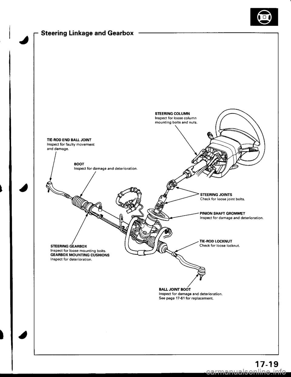
Steering Linkage and Gearbox
STEERING COLUMNInspect tor loose columnmounting bolts and nuts.
TIE.ROD END BALL JOINTInspect tor faultv movementano oamage,
BOOTInspect lor damage and deterioration.
STEERING JOINTSCheck {or loose joint bolts.
PINION SHAFT GROMMETInsp6ct for damage and deterioration.
STEERING
TIE.ROD LOCKNUTCheck {or loose locknut.
Inspect for loose mounting bolts.GEARBOX MOUNTING CUSHIONSInspect for deterioration.
BALL JOINTInspect for damage and deterioration.See pago 17-61 lor replacement.
17-19
Page 672 of 1681
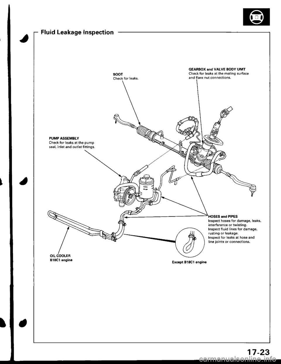
Fluid Leakage Inspection
BOOTCheck for Ieaks.
GEARBOX and VALVE BOoY UNITCheck tor leaks at the mating surfaceand Ilare nut connections,
PUMP ASSEMBLYCheck Ior leaks at the pumD
seal, inlet and outlet fittings.
Inspect hoses for damage, leaks,interfe re n ce or twisting,Inspect fluid lines for damage,rusting or leakage.Inspect for leaks at hose andline ioints or connections.
Bl8Cl engineExc.pl 818Cl engine
17-23
Page 691 of 1681
Power Steering Gearbox
Removal (cont'd)
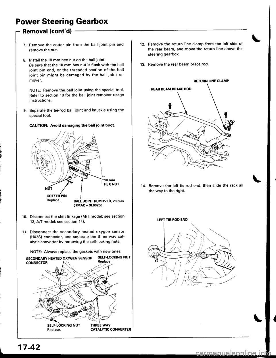
Remove the cotter pin from the ball joint pin and
remove the nut.
Install the 10 mm hex nut on the ball ioint.
Be sure that the 10 mm hex nut is flush with the ball
joint pin end, or the threaded section of the ball
joint pin might be damaged by the ball joint re-
mover.
NOTE: Remove the ball joint using the special tool.
Refer to section 18 for the ball joint remover usage
instructions.
Separate the tie-rod ball ioint and knuckle using the
special tool.
CAUTION: Avoid damaging th. ball ioint boot.
t{ePrace. BALL JOINT REMOVER,23 mm07MAC - SL0020o
10. Disconnect the shift linkage (M/T model: see section
13, A,/T model: see section 14).
11. Disconnect the secondary heated oxygen sensor
(H02Sl connector, and separate the three way cat-
alytic convener by removing the self-locking nuts.
NOTE: Always replace the gaskets with new ones.
SECONDARy HEATED OXycEN SENSOR SELF-LOCKING NUT
17 -42
Replace.CATAI.YTIC CONVERTER
12.
13.
Remove the return line clamp from the left side of
the rear beam, and move the return line above the
steering gearbox.
Remove the rear beam brace rod.
Remove the left tie-rod end. then slide the rack all
the way to the ri9ht.
14.
RETURN LINE CLAMP
LEFT NE-ROD END
Page 693 of 1681
Power Steering Gearbox
Disassembly
Steering Rack Disa3sembly
NOTE:
. Before disassembling the gearbox, wash it off with
solvent and a brush.
. Do not dip seals and O-rings in solvent.
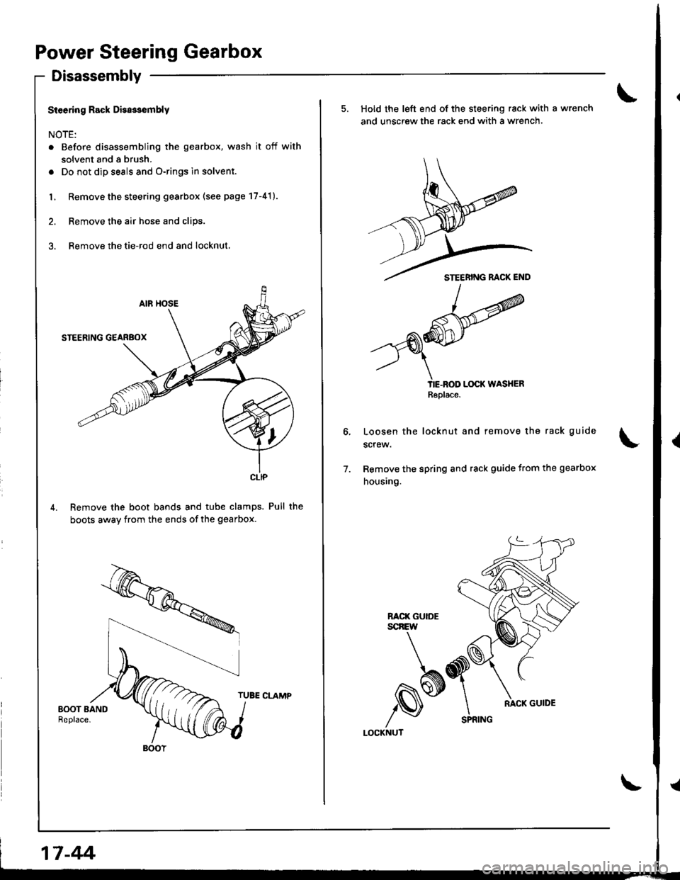
L Remove the steering gearbox (see page 17-41).
2. Remove the air hose and clips.
3. Remove the tie-rod end and locknut,
Remove the boot bands and tube clamps. Pull the
boots away from the ends of the gearbox.
TUBE CLAMP
CLIP
BOOT
17-44
SPRING
5. Hold the left end of the steering rack with a wrench
and unscrew the rack end with a wrench.
TIE-ROD LOCK WASHERBePlace
Loosen the locknut and remove the rack guide
screw.
Remove the spring and rack guide from the gearbox
housing.
7.
RACK GUIDEscnEw
,s*LOCKNUT
RACK GUIDE
Page 706 of 1681
59.
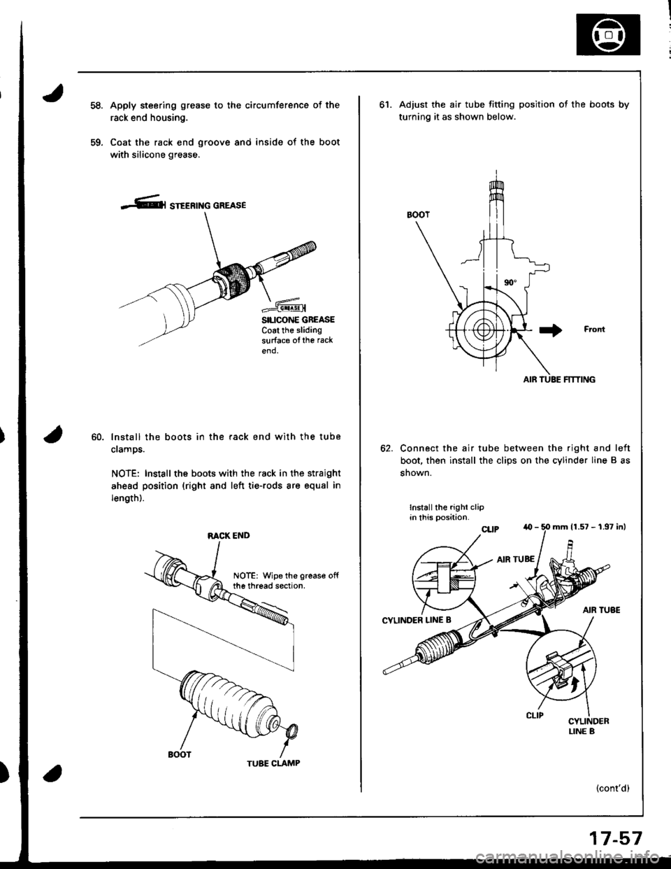
Apply steering grease to the circumference of the
rack end housing.
Coat the rack end groove and inside of the boot
with silicone grease.
-Cl STEERTNG GREASE
SILICONE GBEASECoat the slidingsurface ofthe rack
end.
60.lnstall the boots in the rack end with the tube
clamps.
NOTE: Install the boots with the rack in the straight
ahead position (right and left tie-rods are equal in
length).
RACK END
TUBE CLAMP
17-57
ot.Adjust the air tube fitting position ot the boots by
turning it as shown below.
Connect the air tube between the right and left
boot, then install the clips on the cylinder line B as
snown.
Installthe righi clipin this position.
(cont'd)
mrn 11.57 - 1.97 inl
Page 707 of 1681
Power Steering Gearbox
Reassembly (cont'dl
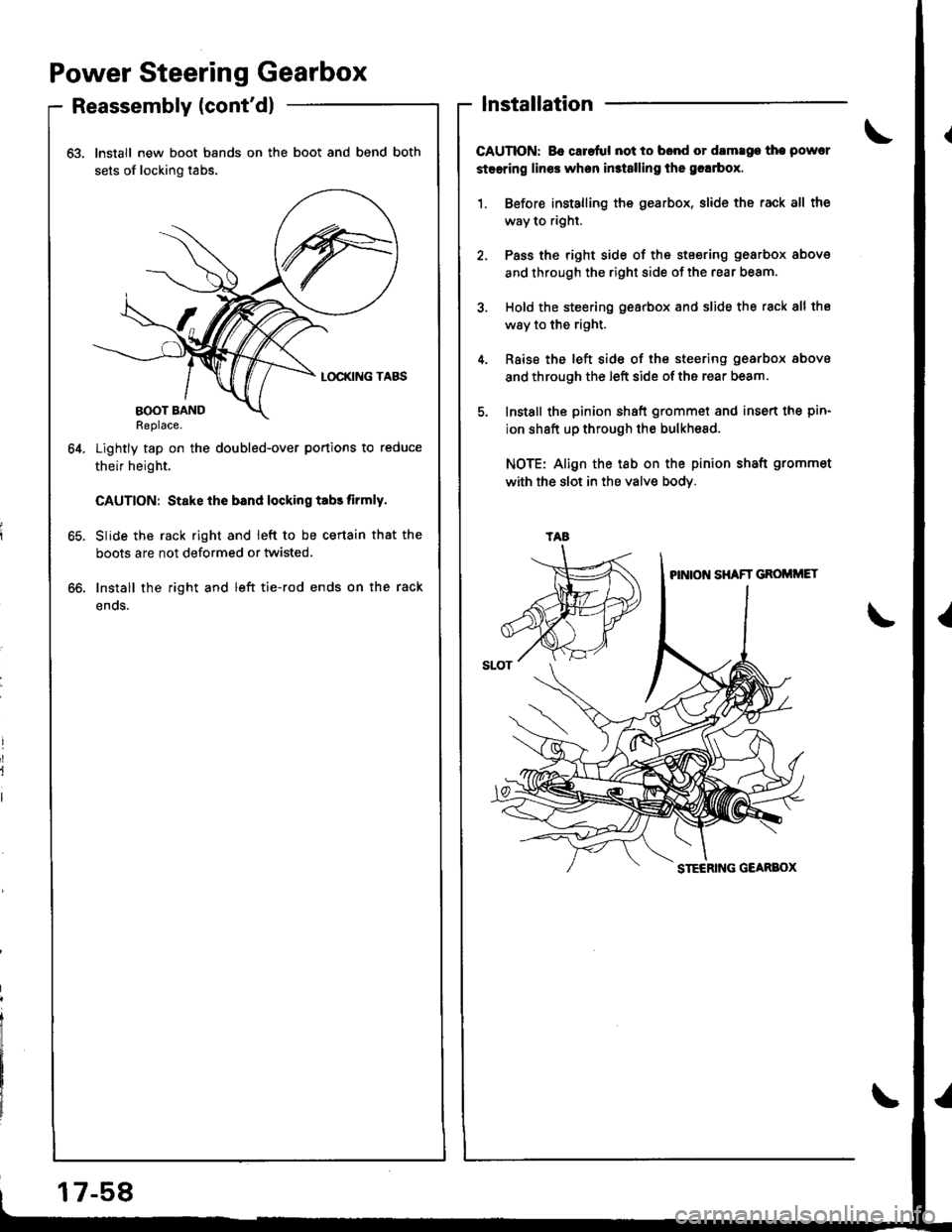
63. Install new boot bands on the boot and bend both
sets of locking tabs.
Lightly tap on the doubled-over portions to reduce
their height.
CAUTION: Stake ihe bsnd locking tabs tirmly.
Slide the rack right and ieft to be certain that the
boots are not deformed or twisted.
Install the right and left tie-rod ends on the rack
enos.
64.
lnstallation
CAUTION: Bo caretul not to bond or damrge the powcr
steering lines when in3t8lling the grlrbox.
1. Before installing the gearbox, slide the rack all the
way to right.
2, Pass the right side of the stsering gearbox above
and through the right side of the rear beam.
3. Hold the steering gearbox and slide the rack 8ll the
way to the right.
4. Rsise the left side of the steering gearbox above
and through the left side of the rear beam.
5. Install the pinion shaft grommet and insert the pin-
ion shaft up through the bulkhesd.
NOTE: Align the tab on the pinion shaft grommet
with the slot in the valve bodY.
oo.
tAa
17-58
Page 710 of 1681
)
)
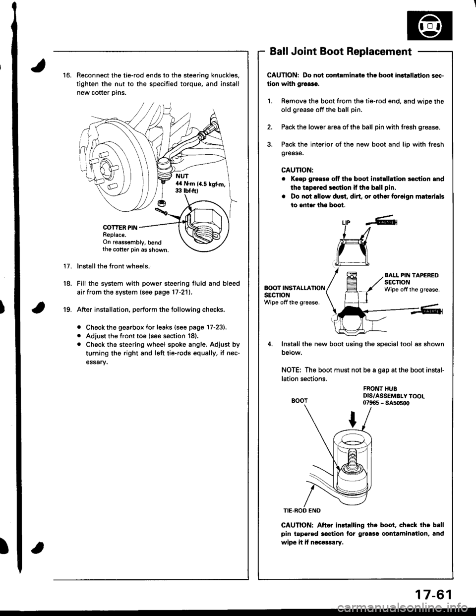
16.Reconnect the tie-rod ends to the steering knuckles,
tighten the nut to the specified torque, and install
new cotter Dins.
COT?ER PINReplace.On reassembly, bendthe cotter pin as shown.
lnstall the front wheels.
Fill the system with power steering fluid and bleed
air from the system (see page 17-21).
After installation, perform the tollowing checks.
. Check the gearbox for leaks (see page l7-23).
. Adjust the front toe (see section 18).
. Check the steering wheel spoke angle. Adjust by
turning the right and left tie-rods equally, it nec-
essary.
Ball Joint Boot Replacement
CAUTION: Do not contaminste th! boot in3tllhtion sec-
tion with grca3o.
1. Remove the boot from the tie-rod end, and wiDe the
old grease off the bsll pin.
2. Pack the lower area of the ball pin with fresh grease.
3. Pack the interior of the new boot and liD with Jresh
grease.
CAUTION:
r Keep grease off tho boot inst.llrtion section 8nd
ths tapered 3cction if tho ball pin.
. Do not lllow du3t. dirt. or other foreign matcrials
to entar lh6 boot.
17.
18.
Lfp -A-1
L:I
ru
Install the new boot using the special tool as shown
Derow.
NOTE: The boot must not be a gap at the boot instal-
lation sections.
CAUTION: Aftor installing tho boot, chock tho ball
pin tapgrgd 3oction tor grorsg conttmination, and
wipe it if nccossary.
BALL PIN TAPEREDsEcnoNWipe offthe grease.BOOT INSTALLATIONsEcnoNWipe off the groaso.
19.
FROI{T HUBDIS/ASSEMBLY TOOL07965 - SA5o5o0
17-61