cable HONDA INTEGRA 1998 4.G User Guide
[x] Cancel search | Manufacturer: HONDA, Model Year: 1998, Model line: INTEGRA, Model: HONDA INTEGRA 1998 4.GPages: 1681, PDF Size: 54.22 MB
Page 323 of 1681
The fuel supply system co
high pressure fuel pump, t
fuel pressure regulator. f
damper, and fuel delivery i
delivers pressure-regulated
cuts the luel delivery when
Fuel Supply System
System Description
consists of a fuel tank, in-tank
r, PGM-Fl main relay, fueffilter,
. fuel injectors, fuel pulsation
y and return lines. This system
ed fuel to the fuel injectors and
rn thq engine is not running.
Fuel Pressure
Relieving
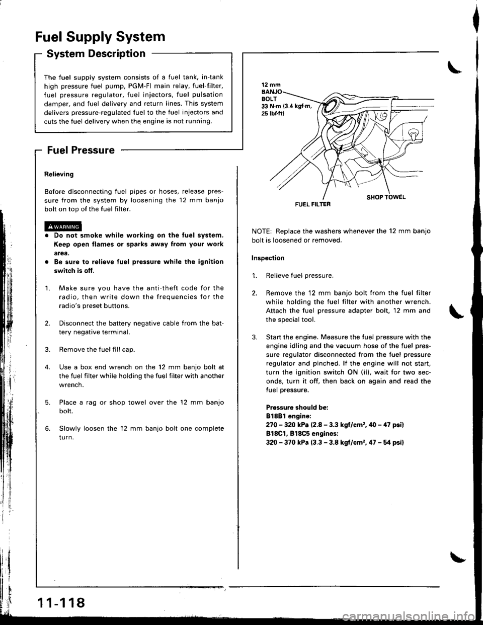
Before disconnecting fuel pipes or hoses, release pres-
sure from the system by loosening the 12 mm banjo
bolt on top ol the fuel filter.
Do not smok€ while working on the tuel system,
Keep open flames or sparks away from you. work
arga.
Be sure to relieve fuel pressure while the ignition
swiich is ofl,
Make sure you have the anti theft code for the
radio, then write down the frequencies for the
radio's preset buttons.
Disconnect the battery negative cable from the bat-
tery negative terminal.
Remove the fuelfill cap.
Use a box end wrench on the 12 mm banjo bolt at
the fuel filter while holding the fuel filter with another
wrench.
Place a rag or shop towel over the '12 mm banjo
bolt.
Slowly loosen the 12 mm banjo bolt one complete
tu rn.
1 1-1 18
I
NOTE| Replace the washers whenever the 12 mm banjo
bolt is loosened or removed.
lnsDection
1. Relieve fuel pressure.
2. Remove the 12 mm banjo bolt from the fuel filter
while holding the fuel tilter with another wrench.
Attach the fuel pressure adapter bolt, 12 mm and
the special tool.
3. Stan the engine. Measure the tuel pressure with the
engine idling and the vacuum hose of the fuel pres-
sure regulator disconnected from the fuel pressure
regulator and pinched. lf the engine will not start,
turn the ignition switch ON (ll), wait for two sec-
onds, turn it off, then back on again and read the
tuel pressure.
Pressuro should be:
Bl8Bl engire:
270 - 320 kP. (2.8 - 3.3 kgl/cm'.40 - 47 psi)
818C1, 818C5 engines:
320 - 370 kPa (3.3 - 3.8 kgt/cm'. 47 - g psi)
12 mm
FUEL FILTER
Page 335 of 1681
l-
Intake Air System
LOCKNUT
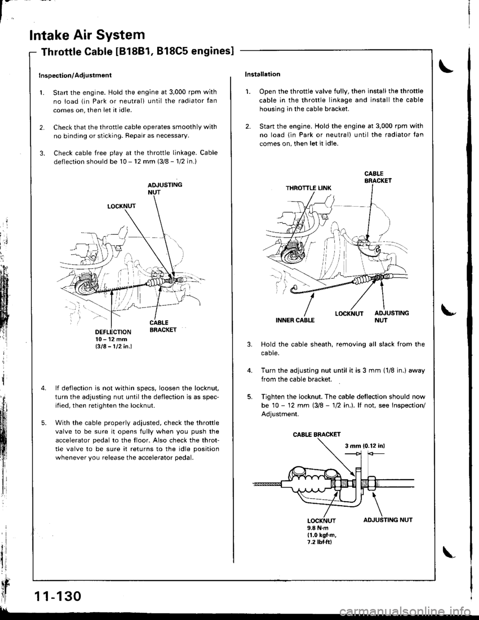
DEFLECTION10-12mmBIA- 112in.l
lf deflection is not within specs, loosen the locknut,
turn the adjusting nut until the deflection is as spec-
ified, then retighten the locknut.
With the cable properly adiusted, check the throttle
valve to be sure it opens fully when you push the
accelerator pedal to the floor. Also check the throt-
tle valve to be sure it returns to the idle position
whenever you release the accelerator pedal.
Throttle Cable IB18B1, 818C5 engines]
Inspection/Adiustment
1. Start the engine. Hold the engine at 3,000 rpm wirh
no load (in Park or neutral) until the radiator tan
comes on, then let it idle.
2. Check that the throttle cable operates smoothly wilh
no binding or sticking. Repair as necessary.
3. Check cable free play at the throttle linkage. Cable
deflection should be 10 - 12 mm (3/8 - 'l12 in.l
ADJUSTINGNUT
t
il
qr
ll1 1-130
!!
TING NUT
\lnstallation
1. Open the throttle valve fully, then install the throttle
cable in the throttle linkage and install the cable
housing in the cable bracket.
2. Start the engine. Hold the engine at 3,000 rpm with
no load (in Park or neutral) until the radiator fan
comes on, then let it idle.
INNER CABLE
Hold the cable sheath, removing all slack from the
caote.
Turn the adjusting nut until it is 3 mm {1/8 jn.) away
from the cable bracket.
Tighten the locknut, The cable deflection should now
be 10 - '12 mm (3/8 - 'll2 in.). lf not, see Inspection/
Adjustment.
3 mm 10.12 inl
u
4.
AD
\
JUSLOCKNUT9.8 N.m(1.0 kgt.m,7,2lbl.ttl
CABI.E
CABI,E BMCKET
Page 336 of 1681
't.
Inspsction/Adiustmsnt
Stan the engine. Hold the engine at 3,000 rpm with
no load in neutral until the radiator fan comes on,
then let it idle.
Check that the throttle cable operates smoothly with
no binding or sticking. Repair as necessary.
Check cable free play at the throttle linkage. Cable
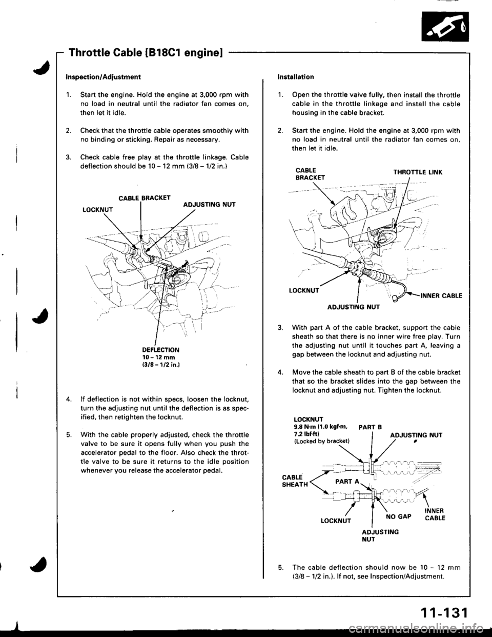
deflection should be 10 - 12 mm (3/8 - 1/2 in.)
DEFTECTION10- 12 mmBIA-112in.l
lf deflection is not within specs, loosen the iocknut.
turn the adjusting nut until the deflection is as spec-
ified, then retighten the locknut.
With the cable properly adjusted, check the throttle
valve to be sure it opens fully when you push the
accelerator pedal to the floor. Also check the throt-
tle valve to be sure it returns to the idle position
whenever you release the accelerator pedal.
CABLE BBACKET
lnstallation
Open the throttle valve fully, then install the throttle
cable in the throttle linkage and install the cable
housing in the cable bracket.
Stan the engine. Hold the engine at 3,000 rpm with
no load in neutral until the radiator fan comes on,
then let it idle.
l.
3.
5.
CABLEBRACKETTHROTTLE LINK
ADJUSTING NUT
With part A of the cable bracket. support the cable
sheath so that there is no inner wire tree plav. Turn
the adjusting nut until it touches part A, leaving a
gap between the locknut and adjusting nut.
Move the cable sheath to oart B of the cable bracket
that so the bracket slides into the gap between the
locknut and adjusting nut. Tighten the locknut.
LOCKNUT9.8 N.m 11.0 kgf.m, PART 87.2lbf.frl(Lockod by bracketl
CABLESHEATH
NO GAPINNERCABLE
ADJUSTINGNUT
The cable deflection should now be 10 - 12 mm(318 - 112 in.l. lf not. see Inspection/Adjustment.
ADJUSTING NUT
1 1-131
Page 337 of 1681
In
Intake Air System
Throttle Body
$;
Description
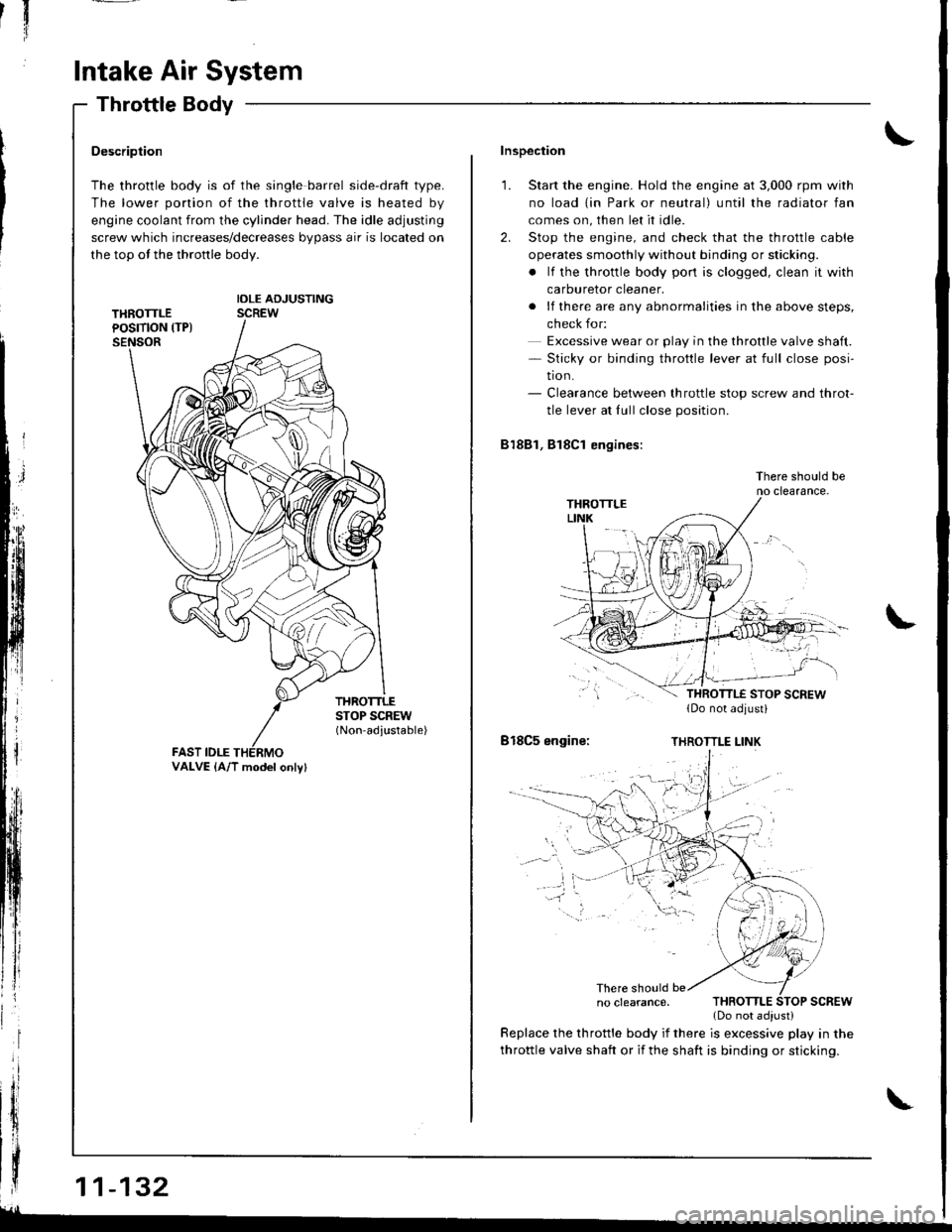
The throttle body is of the single barrel side-draft type.
The lower portion of the throttle valve is heated by
engine coolant from the cylinder head. The idle adjusting
screw which increases/decreases bypass air is located on
the top ot the thronle body.
IDLE ADJUSTINGSCREW
THROTTLESTOP SCREW(Non-adjustable)
FAST IDLE
| | .o clearance. THRoTTLE SToP scREw
{ | | _ .lDonotadiust)
| | y:::::::T,"9":::.'"Tl::f ,::i1::"1" fllyll-'n"
VALVE {A/T model onlv}
Inspection
1. Start the engine. Hold the engine at 3,000 rpm with
no load {in Park or neutral) until the radiator fan
comes on, then let it idle.
2. Stop the engine, and check that the throttle cable
operates smoothly without binding or sticking.
. lf the throttle body pon is clogged, clean it with
carburetor cleaner.
. lf there are any abnormalities in the above steps,
check for:
Excessive wear or play in the throttle valve shaft.- Sticky or binding throttle lever at full close posi-
tion.- Clearance between throttle stop screw and throt-
tle lever at fullclose position.
81881, Bl8Cl engines:
There should beno clearance.
818C5 engine:THROTTLE LINK
There should be
throttle valve shaft or if the shaft is binding or sticking.
glL-
Page 338 of 1681
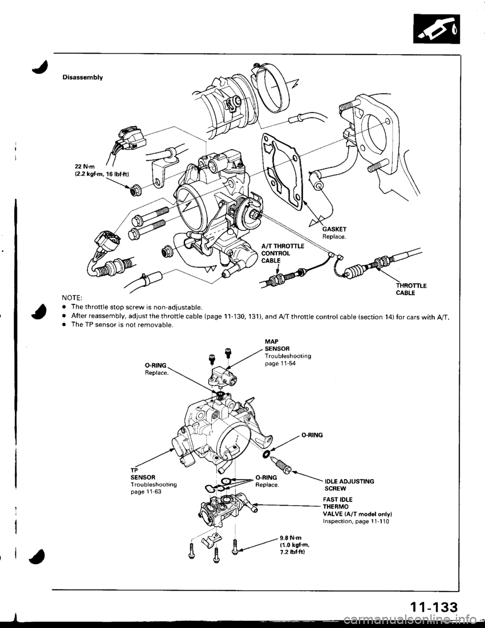
Disassembly
NOTE:
. The throttle stoD screw is non-adiustable.
. After reassembly, adjust the th rottle ca ble (page 11-130, 131),andA/Tthrottlecontrol cable (section l4)Ior cars with A/T.. The TP sensor is not removable.
IOLE ADJUSTINGSCREW
FAST IDLETHERMOVALVE {A/T model onlylInspectaon, page 1 1-l 10
-l
12.2 kgf.m, 16 lbf.ft)
1 1-133
Page 373 of 1681
Transmission Assembly
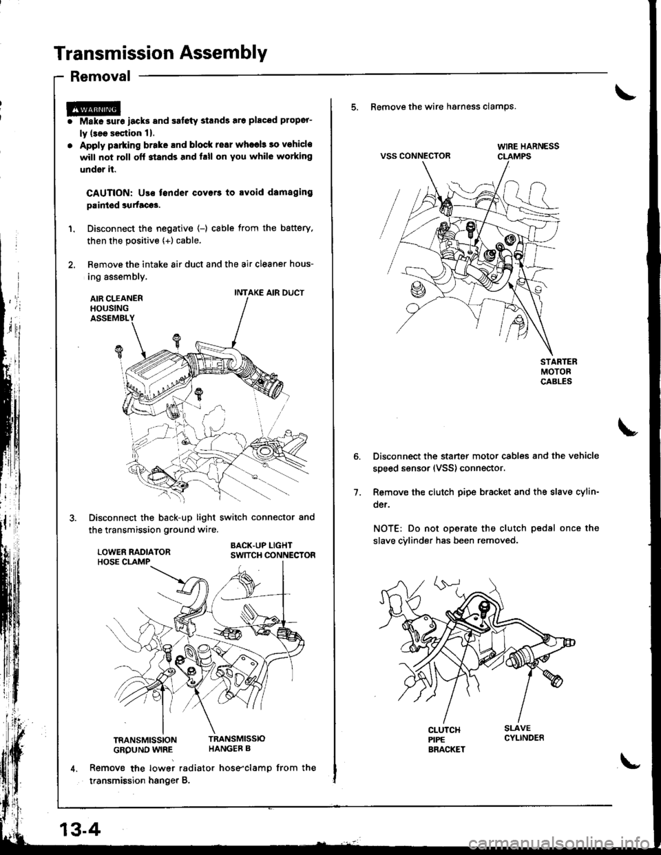
Removal
r@i Make surs iacks and safety stands sro placod propor-
ly (3ee s€ction 1).
. Apply parking brake and block resr whaeb 30 vohicle
will not roll off stands and hll on You whil6 working
under it.
CAUTION: Use fender covers to svoid damaging
paintod surtacos.
1. Disconnect the negative (-) cable from the battery,
then the positive {+) cable.
2. Remove the intake 8ir duct and the air cleaner hous-
ing assembly,
AIR CLEANERHOUSINGASSEMBL
Disconnect the back-up light switch connector and
the transmission ground wire.
BACK.UP LIGHTSWITCH CONNECTOR
TRANSMISSIONTRANSMISSIO
GROUND WIRE HANGEB B
4. Remove tne lowei radiator hose"clamp from the
transmission hsnger B.
INTAKE AIR DUCT
13-4
\-
5. Remove the wire hsrness clamps.
VSS CONNECTOR
Disconnect the starter motor cables and the vehicle
speed sensor (VSS) connector.
Remove the clutch pipe bracket and the slave cylin-
der.
NOT€: Do not operate the clutch pedsl once the
slave cvlinder has been removed.
7.
Page 415 of 1681
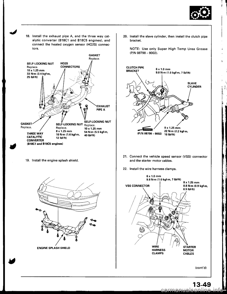
18.Install the exhaust pipe A. and the three way cat-
alytic converter {B18Cl and B18C5 engines), and
connect the heated oxygen sensor {HO2S) connec-
tors.
GASKETReplace.
HO2SCONNECTORSSELF-LOCKING NUTFeplace.10 x 1.25 mm33 N.m {3.4 kg{.m,jj25 rbr.ftl
GASKETReplace.SELF.LOCKING NUTReplace.8 x 1.25 mm'16 N.m (1.6 kgf.m,12 tbtfr)
SELF.LOCKING NUTReplace.10 x 1.25 mm54 N.m (5.5 kgt.m,40 tbt frlTHREE WAYCATALYTICCONVENTER{Bl8Cl and 8'18C5 engincsl
'19. Install the engine splash shield.
20. lnstall the slave cylinder, then instsll the clutch pipe
bracket.
NOTE: Use only Super High Temp Urea Grease(P/N 08798 - 9002).
6x1.0mm9.8 N.m 11.0 kgt m,7 lbI.ft)
SLAVECYLINDER
8 r 1.25 mm22 N.m 12,2 kotm_- 9(x)21 16 tbt.ftt
Connect the vehicle speed sensor (VSS) connestor
and the staner motor cables.
Install the wire harness clamps.
6x1.0mm9.8 N.m {1.0 kgf m, 7 lbt'ft)
VSS CONNECTOR8 x 1.25 mm8.8 N.m {0.9 kg{.m,6.s rbr.ft)
5{P/N 08798
21.
WIREHARNESSCLAMPS
(cont'd)
13-49
Page 416 of 1681
Transmission Assembly
Installation (cont'd)
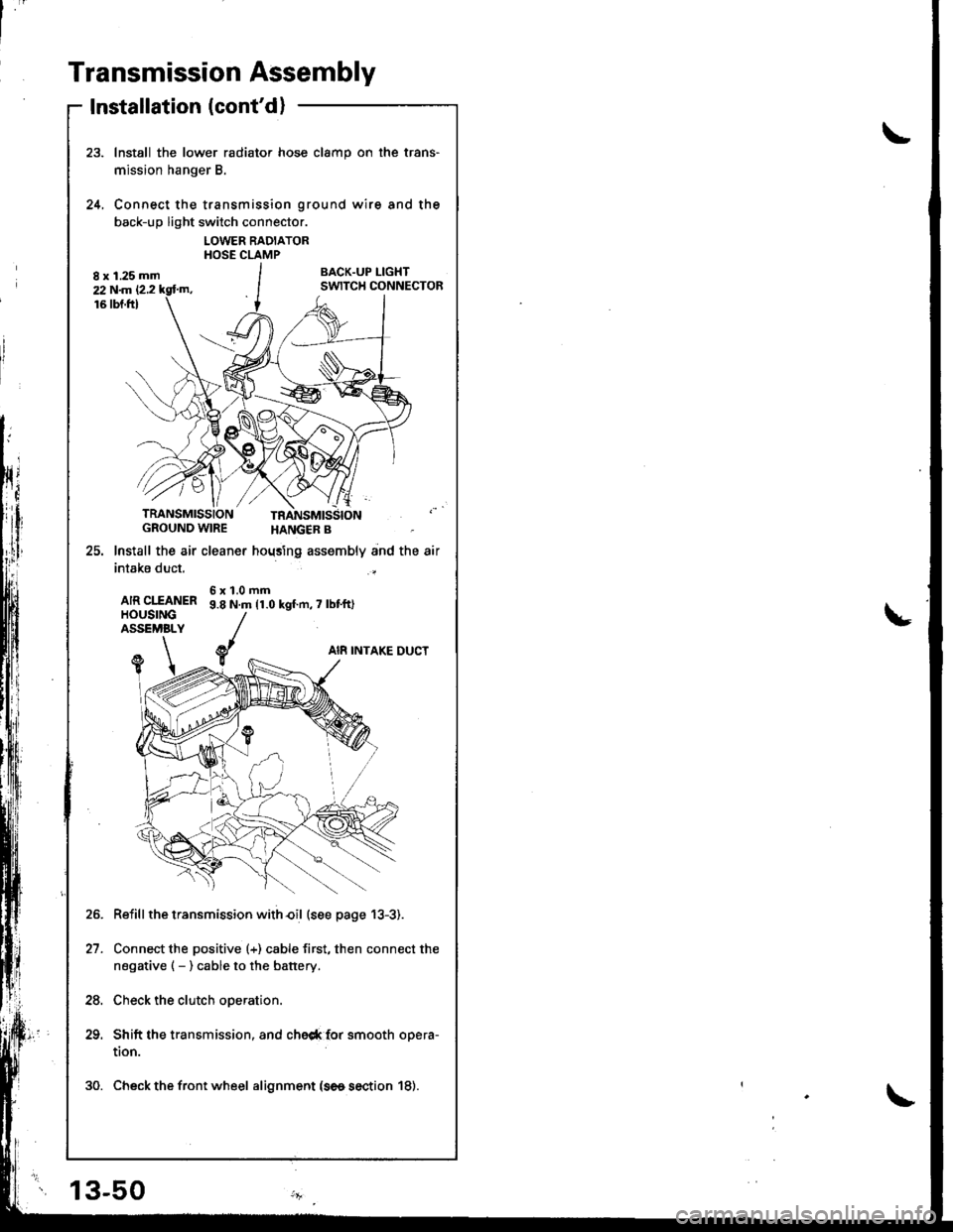
Install the lower radiator hose clamp on the trans-
mission hanger B.
Connect the transmission ground wire and the
back-up light switch connector.
LOWER RADIATORHOSE CLAMP
BACK.UP I-IGHTSWITCH CONNECTOR
24.
TRANSMISSIONGROUND WIRE
25. lnstall the air cleaner
intake duct.
AIR CIfANERHOUSINGASSEMBLY
HANGER B
hoqsing assembly and the air
6x1.0mm9.8 N.m 11.0 kgf.n,7 lbt'ft)
AI8 INTAKE DUCTY1
Reiill the transmission with€il (see page 13-3).
Connect the positive (+) cable first, then connect the
negative ( - ) cable to the battery.
Check the clutch operation.
Shift the transmission, and che6* {or smooth opera-
tion.
30. Check the front wheel alignment (se6 section 18).
21.
24.
13-50
Page 418 of 1681
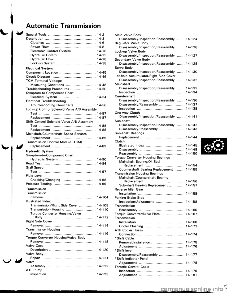
Automatic Transmission
Special Tools ................ '14-2
Descraption .................... 14-3
Clutches ............ ...... 14-6
Power Flow ..,........... 14-8
Electronic Control System ..................... 1 4-1 8
Hydraulic Control ...... 14-23
Hydraulic Flow .........- 14-28
Lock-up System ........ 14-38
Electrical System
Component Location -................................ 1 4-45
Circuit Diagram ............. 14-46
TCM Terminal Voltage/
Measuring Conditions ......,.................... 1 4-48
Troubleshooting Procedures .. . ... ........ ...... ... 14-50
Symptom-to-Component Chart
Electrical System ...... 14-54
Electrical Troubleshooting
Troubleshooting Flowcharts .......... ... ...,.. 14-56
Lock-up Control Solenoid Valve A/B Assembly
Test .................. ...... 14-A7
Replacement ............. 14-a7
Shilt Control Solenoid Valve A/B Assembly
Test .................. ...... '14-88
Replacement .,..,........ 14-88
lvlainshaf t/Countershaft Speed Sensors
Replacement ....-......,. 14-89
Transmission Control Module (TCM)
Replacement ............. 14-89
Hydraulic System
Symptom-to-Component Chart
Hydraulic System ...... 14-90
Road Test ,................... 14-94
Stall Speed
Test .................. ...... 14-97
Fluid Level
Checking/Changing .... 14-98
Pressure Testing ........... 14-99
Transmission
Transmission
Removal ............. ...... 14-104
lllustrated lndex
Transmission/Right Side Cover ............... 1 4-1 08
Transmission Housin9 ................,..,....... 1 4-1'1 O
Torque Converter Housing/ValveBody .................. .. 14-112
Right Side Cover
Removal ............. ...... 14-114
Transmission Housing
Removal ............. ...... 14-1 l6
Torque Converter Housing/Valve Body
Removal ............. ...... l4-1 18
Valve Caps
Description ...........-... 14-120
Valve Body
Repair ................ ...... 14-12'l
Valve
Assembly
ATF Pump
Inspeclton
Main Valve Body
Disassembly/lnspection/Reassembly
Regulator Valve Body
Disassembly/lnspection/Reassembly
Lock-up Valve Body
Disassembly/lnspection/Reassembly
Secondary Valve Body
Disassembly/lnspection/Reassembly
Servo Body
....... 14-124
....... 14-126
....... 14-127
....... 14 124
Disassembly/lnspection/Reassembly .......
1st-hold Accumulator/Right Side Cover
Disassembly/lnspection/Reassembly .......
Mainsha{t
14-130
14-132
Disassembly/lnspection/Reassembly ....... 14-133
Inspection ................. 14-134
Countershaft
Disassembly/lnspection/Reassembly,..,.., l4-136
Disassembly/Reassembly ..,...,..,.........,,.. 1 4-1 37
Inspection ......,...,..,... 14-138
One-way Clutch
Disassembly/lnspection/Reassembly ....,.. 14-141
Sub-shaft
Disassembly/lnspection/Reassembly ...,,..'14-142
Disassembly/Reassembly ....................... 1 4- l 43
Sub-shaft Bearings
Replacement ,..,,.,,..,.. 14-144
Clutch
lllustrated Index ................................... I 4-1 45
Disassembly ............. 14-144
Reassembly .............. 14-150
Torque Converter Housing Bearings
Mainshaft Bearing/Oil Seal
Replacement ......... 14-154
Countershaft Bearing Replacement ......... 1 4- 1 55
Transmission Housing Bearings
Mainshaft/Countershaft BearingReplacement ......,.. 14-'156
Sub-shaft Bearing Replacement .,............ 1 4-1 57
Reverse ldler Gear
Installation .........-..... 14-158
Parking Brake Stop
Inspection/Adjustment .......................... 1 4-1 58
Transmission
Reassembly .............. 14-160
Torque Converler/Drive Plate ..............,.,,.,, 1 4-1 67
Transmission
Installation ............... 14-168
Cooler Flushing ......... 14-172
ATF Cooler Hoses
Connection ,..,,,....,,.,, '14-'174
*shift cable
Removal/lnstallation . . .. .... ... .... ... .... .. . ... .. 14-'l75
Adjustment ,..,...,,,,.,, 14-'116*Shilt lever
Disassembly/Reassembly ....................... 1 4-'17 7'Shift Indicator Panel
Adjustment .............. 14-178
\l
)g
Page 508 of 1681
L
\a
\."tl
14-91
J
al
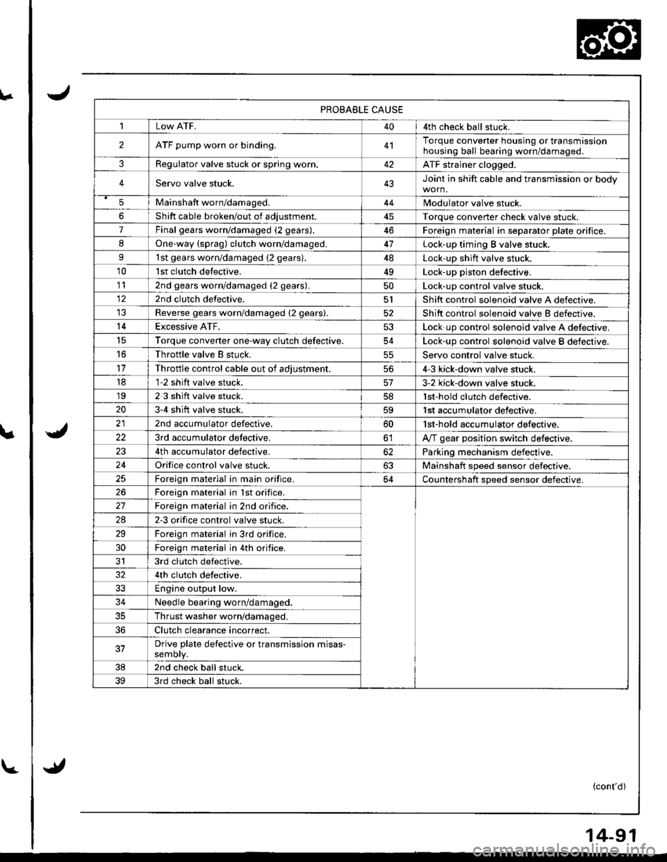
PROBABLE CAUSE
1Low ATF.404th check ball stuck.
2ATF pump worn or binding.4'lTorque converter housing or transmissionhousing ball bearing worn/damageo.
3Regulator valve stuck or spring worr..42ATF strainer clogged.
4Servo valve stuck.43Joint in shift cable and transmission or body
5Mainshaft worn/damaged.44Modulator valve stuck.
6Shift cable broken/out of adiustment45Torque converter check valve stuck.
7Final gears worn/damaged (2 gears).46Foreign material in separator plate orifice.
8One.way {sprag) clutch worn/damaged.47Lock-up timing B valve stuck.
91st gears worn/damaged {2 gears).4ALock-up shift valve stuck.
10lst clutch defective.49Lock-up piston defective.
112nd gears worn/damaged (2 gears).50Lock-up control valve stuck.
122nd clutch defective.5lShift control solenoid valve A defective.
Reverse gears worn/damaged (2 gears).52Shift control solenoid valve B defectrve.
14Excessive ATF.53Lock up control solenoid valve A defective,'t5Torque converter one-wav clutch defective.54Lock-up control solenoid valve B defective.
16Throttle valve B stuck.55Servo control valve stuck.
11Throttle control cable out of adiustment.564-3 kick-down valve stuck.
181-2 shift valve stuck.3-2 kick-down valve stuck.'192 3 shift valve stuck.lst-hold clutch defective.
203-4 shift valve stuck.59'| st accumulator defective.
2nd accumulator defective.60'lst-hold accumulator defective,
223rd accumulator delective,olA,rf gear position switch defective,
4th accumulator defective.62Parking mechanism defective.
24Orifice control valve stuck.63Mainshaft speed sensor defective.
Foreign material in main orifice.64Countershaft speed sensor defective.
26Foreign material in lst orifice.
Foreign material in 2nd orifice.
2A2-3 orifice control valve stuck.
29Foreign material in 3rd orifice.
30Foreign material in 4th orifice.
JI3rd clutch defective.
4th clutch defective.
33Engine output low.
34Needle bearing worn/damaged.
35Thrust washer worn/damaged.
36Clutch clearance incorrect.
37Drive plate defective or transmission misas-semory.
382nd check ball stuck.
393rd check ball stuck.
(cont'd)