cable HONDA INTEGRA 1998 4.G Owner's Manual
[x] Cancel search | Manufacturer: HONDA, Model Year: 1998, Model line: INTEGRA, Model: HONDA INTEGRA 1998 4.GPages: 1681, PDF Size: 54.22 MB
Page 510 of 1681
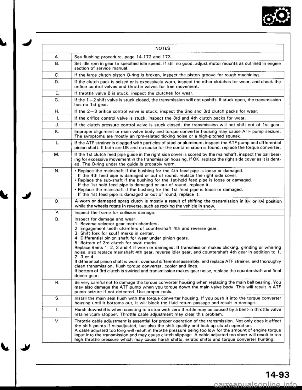
NOTES
See flushing procedure, page 14-172 and 173.
B.Set idle rpm in gear to specilied idle speed. lf still no good, adjust motor mounts as outlined in enginesection of service manual.
c.lf the large clutch piston O-.ing is broken, inspect the piston groove for rough machining.
D.lf the clutch pack is seized or is excessively worn, inspect the other clutches lor wear, and check the
orifice control valves and throttle valves for free mov€ment.
E.lf throttle valve B is stuck. insDect the clutches for wear.
lf the 1 - 2 shift valve is stuck closed, the transmission will not upshitt. lf stuck open, the transmissionhas no lst gear.
H.lf the 2-3 orilice control valve is stuck, inspect the 2nd and 3rd clutch packs for wear.
lf the orifice control valve is stuck. inspect the 3rd and 4th clutch packs for wear.
J.lf the clutch pressure control valve is stuck closed, the transmission will not shift out oI 1st gear.
lmproper alignment or main valve body and torque converter housing may cause ATF pump seizure.
The symptoms are mostly an rpm-related ticking noise or a high-pitched squeak.
lf the ATF strainer is clogged with particles of steel or aluminum, inspect the ATF pump and differentialpinion shaft. lf both are OK and no cause for the contamination is found, replace the torque converter.
M.lf the 1st clutch feed pipe guide in the right side cover is scored by the mainshaft, inspect the ball bear-
ing lor excessive movement in the transmission housing. lf OK, replace the right side cover as it is dent-
ed. The O-ring under the guide is probably worn.
N.Replace the mainshaft if the bushing for the 4th feed pipe is loose or damaged.lf the 4th feed pipe is damaged or out of round, replace the right side cover.Replace the sub-shaft il the bushing for the 1st-hold teed pipe is loose or damaged.lf the 1st-hold teed pipe is damaged or out of round, replace it.
Replace the mainshaft iI the bushing for the lst feed pipe is loose or damaged.lf the 1st leed pipe is damaged or out of round, replace it.
A worn or damaged sprag clutch is mostly a result of shifting the transmission in El or LDll position
while the wheels rotate in reverse, such as rocking the vehicle in snow.
P.Inspect the trame for collision damage.
Inspect lor damage and wear:1. Reverse selector gear teeth chamfers.2. Engagement teeth chamfers of countershaft 4th and reverse gear.
3. Shift fork for scuff marks in center.4. Differential pinion shaft tor wear under pinion gears.
5. Bottom of 3rd clutch for swirl marks.Replace items 1 . 2, 3 and 4 iI worn or damaged. lf transmission makes clicking, grinding or whirringnoise, also replace mainshaft 4th gear, reverse idler gear, and countershatt 4th gear in addition to '1,
2,3or4.It differential pinion shalt is worn, overhaul differential assembly, and replace ATF strainer, and thoroughly
clean transmission, tlush torque conveder, cooler and lines.lf bottom ot 3rd clutch is swirled and transmission makes gear noise, replace the countershaft and final
onven qear.
R.Be very careful not to damage the torque converter housing when replacing the main ball bearing. You
may also damage the ATF pump when you torque down the main valve body. This will result in ATFpump seizure if not detected. Use proper tools.
S.Install the main seal llush with the torque converter housing. lf you push it into the torque converterhousing until it bottoms out. it will block the fluid return passage and result in damage.
T.Harsh downshifts when coasting to a stop with zero throttle may be caused by a bent-in throttle valve
retainer/cam stopper. Throttle cable adjustment may clear this problem.
Throttle cable adjustment is essential tor proper operation ol the transmission. Not only does it affectthe shift points if misadjusted, but also the shift quality and lock up clutch operation.A cable adjusted too long will result in throttle pressure being too low for the amount of engine torqueinput into the transmission and may cause clutch slippage. A cable adjusted too short will result in toohiqh throttle pressure which may cause harsh shifts, erratic shifts and torque converter hunting.
Page 518 of 1681
\a
t
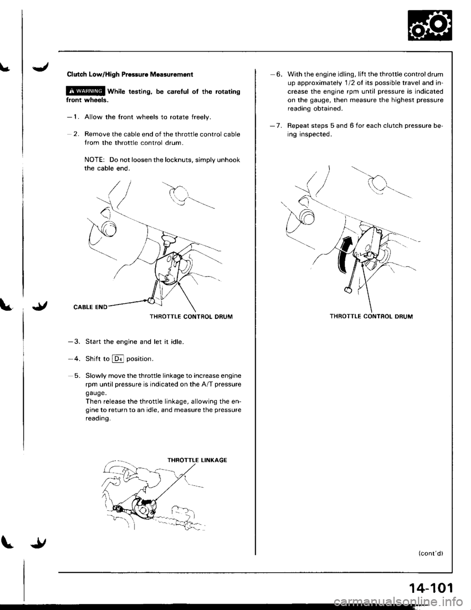
Clutch LoWHigh Prossuro Moasursment
@ wnire t6sting, be carelul of the rotating
front whaols.
- 1. Allow the front wheels to rotate freelv.
2. Remove the cable end of the throttle control cable
trom the throttle control drum.
NOTE: Do not loosen the locknuts, simply unhook
the cable end.
THROTTLE CONTROL DRUM
-3. Start the engine and let it idle.
-4. Shitt to @ position.
5. Slowly move the throttle linkage to increase engine
rpm until pressure is indicated on the A/T pressure
gauge.
Then release the throttle linkage, allowing the en-
gine to return to an idle, and measure the pressure
reading.
6. With the engine idling. lift the throttle controldrum
up approximately 'l12 of its possible travel and in-
crease the engine rpm until pressure is indicated
on the gauge, then measure the highest pressure
reading obtained.
- 7. Repeat steps 5 and 6 for each clutch pressure be-
ing inspected.
d
Q^--,'.-
THROTTLE CONTROL DRUM
(conr'd)
14-101
Page 520 of 1681
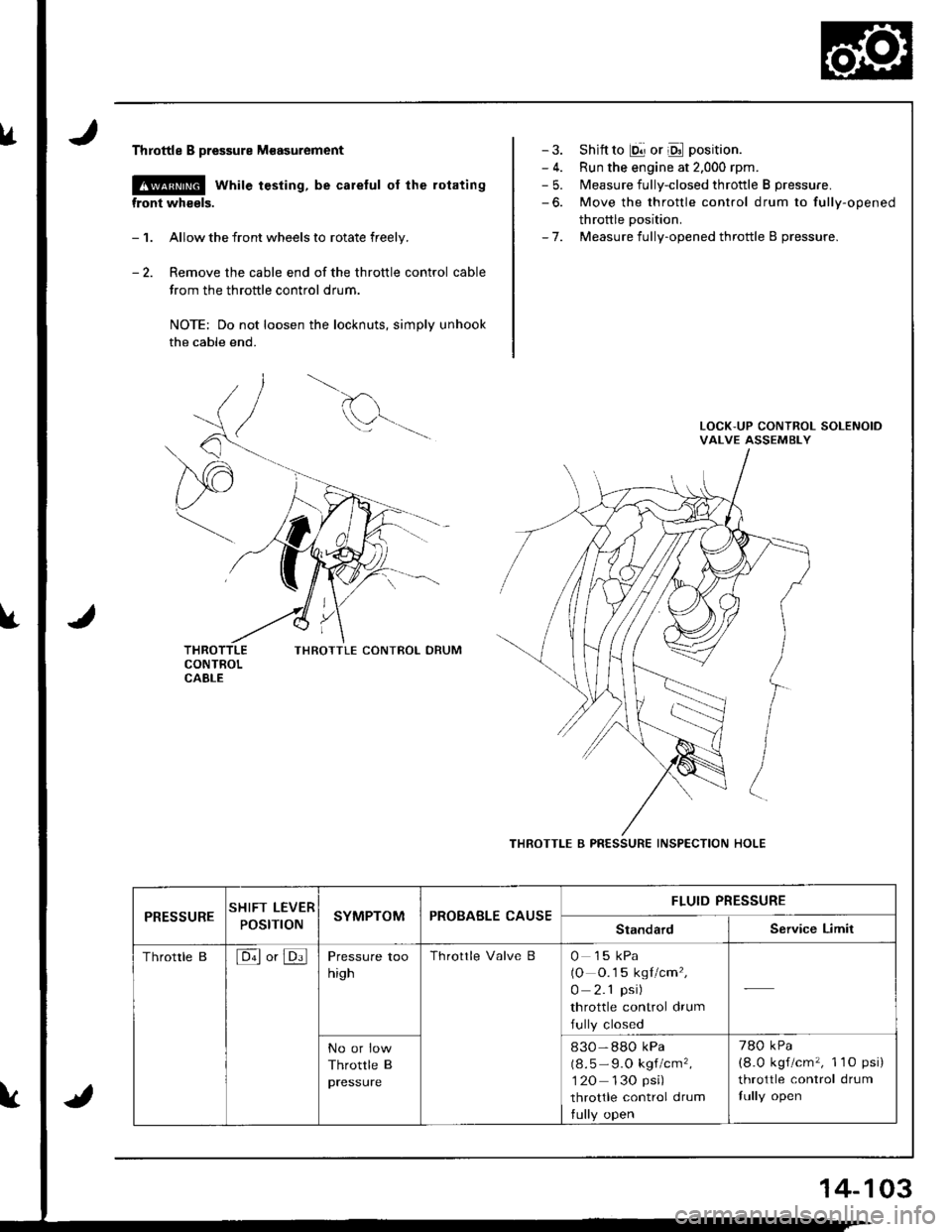
lrThrottle B pressure M€asurement
@ while testing, be careful of the rotating
front wheels.
- 1. Allow the front wheels to rotate freely.
- 2. Remove the cable end of the throttle control cable
trom the throttle control drum.
NOTE: Do not loosen the locknuts, simply unhook
the cable end.
THROTTLE CONIBOL DRUM
- 3. Shift to E!] or Oll position.
- 4. Run the engine at 2.000 rpm.- 5. Measure fully-closed throttle B pressure.
-6. Move the throttle control drum to fully-opened
throttle Dosition.- 7. Measure fully-opened throttle B pressure.
THROTTLE B PRESSURE INSPECTION HOLE
PRESSURESHIFT LEVER
POStnONSYMPTOMPROBABLE CAUSEFLUID PRESSURE
StandardService Limit
Throttle B[6ll or JDi]Pressure too
high
Throttle Valve B0 15 kPa(O O.1 5 kgl/cm',
0 2.1 psi)
throttle control drum
fully closed
No or low
Throttle B
pressure
830-88O kPa
(8.5 - 9.O kgf/cm',
1 20 130 psi)
throttle control drum
tully open
780 kPa
(8.0 kgf/cm', 1 1O psi)
throttle control drum
fully open
14-103
Page 521 of 1681
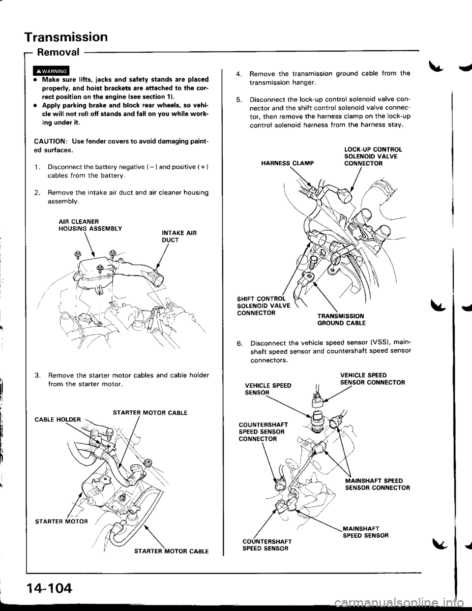
Transmission
Removal
. Make sure lifts, iacks and salety stands are placed
properly, and hoist brackets are attached to lhe cor-
rect position on the engine (see section 11.
. Apply parking brake and block real wheels, so vehi-
cle will nol roll off stands and fall on you while work-
ing under it.
CAUTION: Use fender covers to avoid damaging paint-
ed surtaces.
1 . Disconnect the battery negative (- ) and positive { + )
cables from the battery.
2. Remove the intake air duct and air cleaner housing
assemoty.
AIR CLEANERHOUSING ASSEMBLY
Remove the starter motor cables and cable holder
from the starter motor.
MOTOR CABLECABLE HOLDER
STARTER MOTOR'/,/ \
STARTER MOTOR CABI-E
14-104
-
5.
Remove the transmission ground cable from the
transmission hanger.
Disconnect the lock-up control solenoid valve con-
nector and the shift control solenoid valve connec-
tor, then remove the harness clamp on the lock-up
control solenoid harness from the harness s1ay.
HARNESS CLAMP
TRANSMISSIOIGROUND CABLE
Disconnect the vehicle speed sensor (VSS), main-
shalt speed sensor and countershalt speed sensor
connecrors.
{
6.
VEHICLE SPEED
VEHICLE SPEED
ll t2tor coNNEcroR
V
MAINSHAFT SPEEDSENSOR CONNECTOR
MAINSHAFTSPEED SENSORCOUNTERSHAFTSPEED SENSOR{
Page 523 of 1681
Transmission
Removal (cont'd)
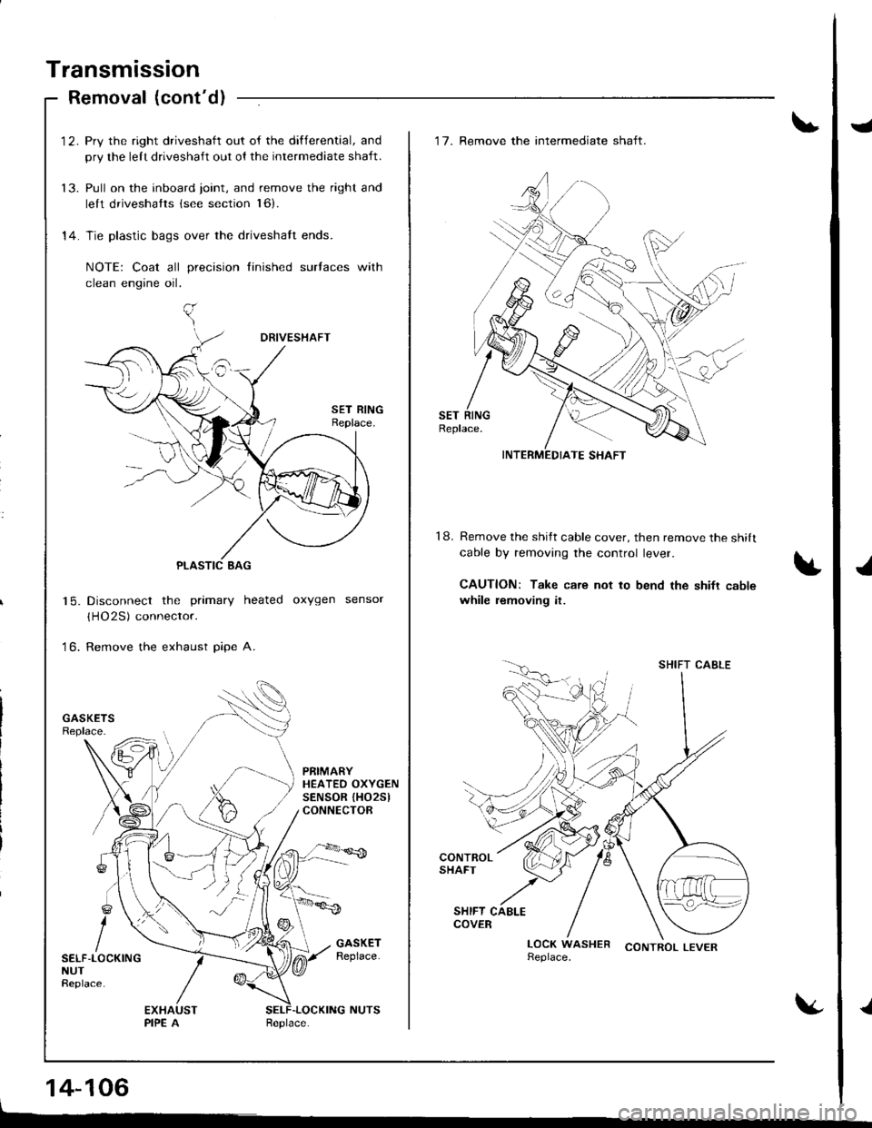
'12. Pry the right driveshaft out of the differential, and
pry the lelt driveshaft out ol the intermediate shaft.
13. Pull on the inboard joint, and remove the right and
lelt driveshatts (see section l6).
14. Tie plastic bags over the driveshalt ends.
NOTE: Coat all precision finished surlaces with
clean engine oil.
Disconnect the primary heated oxygen sensor
(HO2S) connector.
Remove the exhaust pipe A.
| 5.
to.
PRIMARYHEATEO OXYGENSENSOR {HO25lCONNECTOR
SELF-LOCKINGNUTReplace.
14-106
J
J
.l
18.
'17. Remove the intermediate shaft.
Remove the shitt cable cover, then remove the shilt
cable by removing the control lever.
CAUTION: Take care not to bend the shifr cablewhile removing it.
CONTROL LEVER
INTERMEDIATE SHAFT
SHIFT CABLE
Page 524 of 1681
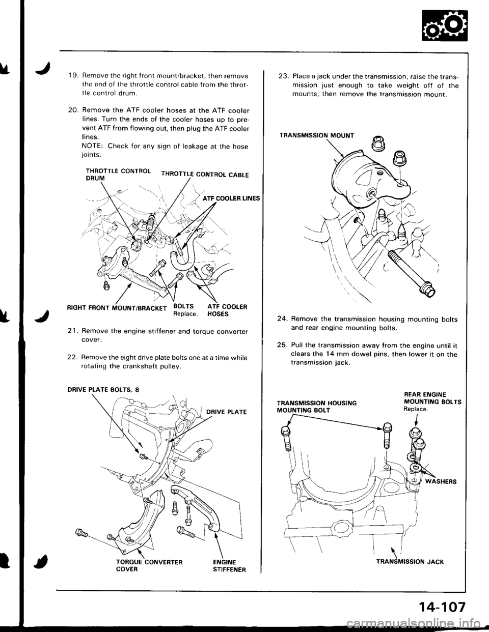
u19.Remove the right front mount/bracket, then remove
the end of the throltle control cable from the throt-
tle control drum.
Remove the ATF cooler hoses at the ATF cooler
lines. Turn the ends of the cooler hoses up to pre-
vent ATF from flowing out, then plug the ATF cooler
lines.
NOTE: Check for any sign ol leakage at the hosejornrs.
THROTTLE CONTROL CABLE
20.
f
RIGHT FRONT MOUNT/BRACKET
21. Remove the engine stiftener and torque converter
cover,
22. Remove the eight drive plate bolts one at a time whilerotating the crankshaft pulley.
EOLTS ATF COOLERReplace. HOSES
ENGINESTIFFENERCOVERTRA
14-107
23. Place a jack under the transmission. raise the trans-mission just enough to take weight off of the
mounts, then remove the transmtssion mount.
TRANSMISSION MOUNT
24. Remove the transmission housing mounting bolts
and rear engine mounting bolts.
25. Pull the transmission away trom the engine until itclears the 14 mm dowel pins, then lower it on thetransmission jack.
REAR ENGINEMOUNTING BOLTSReplace.
WASHERS
MISSION JACK\NS
Page 585 of 1681
7.
10 x 1.25 mm1+4 N.m (4.5 kgt.m,33 tbf.ft)
TOROUECONVERTERCOVER
EI{GINESTIFFEI{ER
I x 1.25 mm24 N.m 12.4 kgf.m,17 rbf.ftl
8.
Remove the transmission jack.
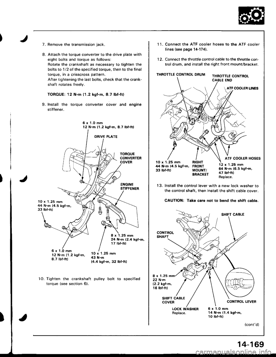
Attach the torque converter to the drive plate with
eight bolts and torque as lollows:
Rotate the crankshatt as necessary to tighten the
bolts to 1/2 of the specified torque, then to the final
torque, in a crisscross pattern.
After tightening the last bolts, check that the crank-
shaft rotates freely.
TOROUE: 12 N.m (1.2 kgf.m. 8.7 lbf.ft)
Install the torque converter cover and engine
stitfener.
6 x 1.0 mm12 N'm l'1.2 kgl.m,8.7 lbl.ftl
ORIVE PLATE
9.
6 x '1.0 mm12 N'm ('1.2 kgf.m,8.7 tbt.fr)
l0 x 1.25 mm43 N.m{4.4 kgf.m, 32 lbl.ftl
10.Tighten the crankshaft
torque (see section 6).
pulley bolt to specified
)
1 1. Connect the ATF cooler hoses to the ATF cooler
lines (see page 14-174).
12. Connect the throttle control cable to the throtrle con,
trol drum, and installthe right front mount/brackel.
THROTTLE CONTROL DRUMTHROTTLE CONTROLCABLE END
ATF COOLER UNES
ATF COOLER HOSESlO x 1.25 mm RIGHT44 N.m 14.5 kgf.m, FRONT33 tbf.ft) MoUNT/BRACKET
13.
LOCK WASHERReplace.6 x 1.0 mft14 N.m (1.4 kgt.m,10 tbf.fr)
12 x 'l ,25 nn64 N.rh 16.5 kgf.m,47 tbt.ft)Replace.
SHIFT CABLE
CONTROL LEVER
(cont'dl
Install the control lever with a new lock washer to
the control shalt, then installthe shift cable cover.
CAUTION: Take care not to b6nd the shitt cable.
8 x 1.2522 N-m12.2 kgt.n.'t6 tbl.tr,
SHIFT CABLECOVER
14-169
Page 587 of 1681
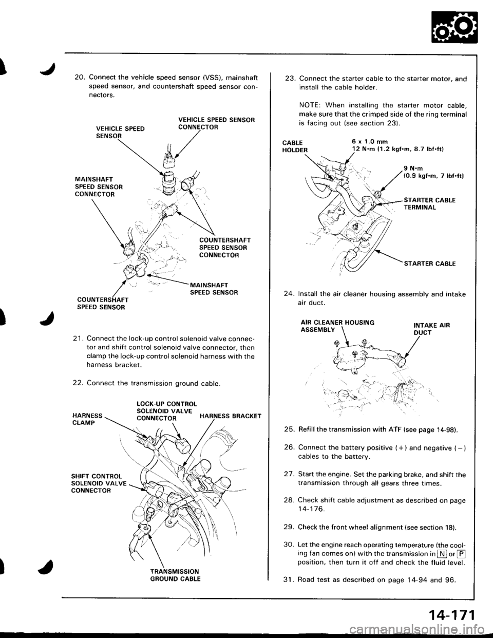
I20.Connect the vehicle speed sensor (VSS), mainshaft
speed sensor, and countershaft sDeed sensor con-
nectors.
VEHICLE SPEED SENSORCONNECTOB
)
k/
t"J
21. Connect the lock-up control solenoid valve connec-
tor and shift control solenoid valve conneclor, then
clamp the lock-up control solenoid harness with the
harness bracket.
22. Connect the transmission ground cable.
SPEED SENSOR
LOCK-UP CONTROLSOLENOID VALVECONNECTOR
23.Connect the starter cable to the starter motor, and
install the cable holder.
NOTE: When installing the starter motor cable,
make sure that the crimped side ol the ring terminal
is facing out (see section 23).
6 x 1.0 mm12 N.m {1 .2 kgf.m, 8.7 lbl.ft)
9 N.m(0.9 kgf.m, 7 lbt.ttl
STARTER CABLETERMINAL
STARTER CABLE
24.Install the air cleaner housing assembly and intake
arr oucl.
AIR CLEANER HOUSINGINTAKE AIRASSEMBLY
27.
Refill the transmission with ATF {see page 14-98).
Connect the battery positive (+ ) and negative { - }cables to the battery.
Start the engine. Set the parking brake, and shift the
transmission through all gears three times.
Check shilt cable adjustment as described on page
14-176.
Check the front wheel alignment (see section 18).
Let the engine reach operating temperature (the cool-ing fan comes onl with the transmission in S or @position, then turn it off and check the fluid level.
31. Road test as described on page 14-94 and 96.
25.
26.
24.
29.
30.
14-171
Page 591 of 1681
)
I
t
Shift Cable
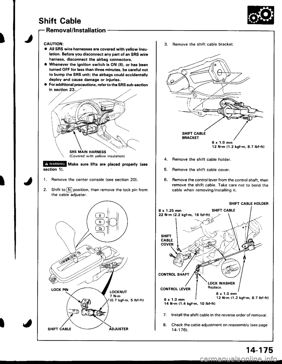
Removal/lnstallation
CAUTION:
a All SRS wile ham€sses ar6 covcred with yollow insu-
lation. Befols you disconnect any part of an SRS wil6
harness, disconnect tho ailbag connoctors.
a Whenever th€ ignition switch is ON (ll), or has be€n
turned OFF for less than thr€e minutes, be caroful not
to bump tho SRS unit; tha airbags could accidentally
deploy and caus6 damags or iniuri€s.a For additional precautions, .ofer to th€ SRS sub-soction
!@! -u^" sure rrrs are praceq propeny rs€o
ssction 1).
'1. Remove the center console (see section 20).
2. Shift to N position, then remove the lock pin from
the cable adjuster.
_llr_8J.ll^/l
@i[ )l
@ll-11---l rr
LOCKNUT7 N.m10.7 kgt.m, 5 lbf.fr)
3. Remove the shift cable bracket.
6 x 1.0 mm12 N.m (1.2 kgt.m,8.7 lbf.ftl
4. Remove the shitt cable holder.
5. Remove the shift cable cover.
6. Remove the control lever from the controlshaft, then
remove the shift cable. Take care not to bend the
cable when removing/installing it.
SHIFT CABLE HOLDER
Installthe shitt cable in the reverse order ot removal.
Check the cable adjustment on reassembly {see page't 4-1761.
7.
8.
12 N.m (1.2 kgf.m,8.7 lbf.ft)
14 N.m 11.4 kgf.m, 10 lbl.ftl
14-175
Page 592 of 1681
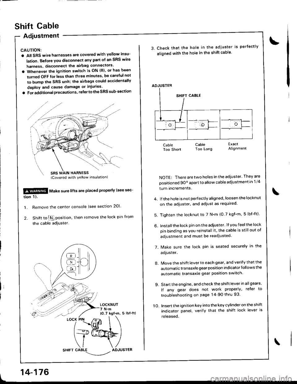
Adiustment
CAUTION:
a All SRS wile harnesses are covered with yellow insu-
lation. Belore you disconnect any part ol an SRS wire
harness, disconnect the akbag connectors'
a Whenever the ignition switch is ON (ll), or has been
tumed OFF tol less than three minutes, be caletul not
to bump the SRS unit; the airbags could accidentally
deploy and cause damage or injuries'
a For additionalprecautions, referto the SRS sub-section
SBS MAIN HARNESS(Covered with yellow inslrlationl
$!@ rtl"t . "ure lifts are placed plope y lsee sec-
tion 1 l.
'1. Remove the center console lsee section 20)'
2. Snitt to $ position, then remove the lock pin lrom
the cable adjuster'
LOCKNUT7 N.m10.7 kgf.m, 5 lbf.fl)
t
]H
@
@
@
{l
LOCK PIN
14-176
shift cable
3. Check that the hole in the adjuster is perfectly
sligned with the hole in the shift cable'
CableToo Short
NOTE: There are two holes in the adjuster. They are
positioned 9Oo apart to allow cable adiustment in 1/4
turn Incremenrs.
4. lJ the hole is not per{ectly aligned, loosen the locknut
on the adjuster, and adiust as required.
5. Tighten the locknut to 7 N'm (0.7 kgf'm, 5lbf'ftl
6. Installthe lock pin on the adiuster. lI you feelthe lock
pin binding as Vou reinstall it, the cable is still out ot
adjustment and must be readjusted.
7. [/ake sure the lock pin is seated securely in the
aoJusrer.
8. Move the shift lever to each gear, and verify that the
automatic transaxle gear position indicator follows the
automatic transaxle gear position swatch.
9. Start the engine, and check the shift lever in allgears'
lf any gear does not work properly, refer to
troubleshooting on page 14-90 thru 93.
10. Insert the ignition key into the key cylinder on the shift
indicator panel, verify that the shift lock lever is
released.
CableToo Long
ExactAlignment
\
ADJUSTER