cable HONDA INTEGRA 1998 4.G Repair Manual
[x] Cancel search | Manufacturer: HONDA, Model Year: 1998, Model line: INTEGRA, Model: HONDA INTEGRA 1998 4.GPages: 1681, PDF Size: 54.22 MB
Page 950 of 1681
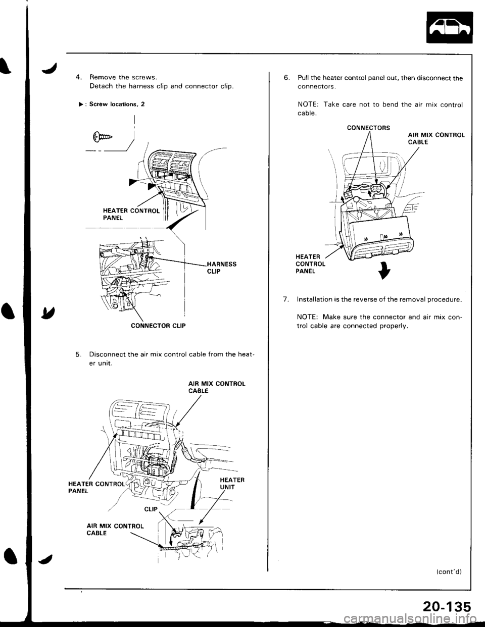
4. Remove the screws.
Detach the harness clip and connector clip.
> : Screw locations, 2
CONNECTOR CLIP
5.Disconnect the air mix control cable from the heat-
er unit.
AIR MIX CONTROLCABLE
CONNECTORS
6.Pull the heater control panel out, then disconnect the
connectors.
NOTEr Take care not to bend the air mix control
ca ote.
HEATERCONTROLPANEL
7. Installation is the reverse of the removal procedure.
NOTE: Make sure the connector and air mix con-
trol cable are connected properly.
(cont'd)
20-135
Page 953 of 1681
Dashboard
Replacement Precautions
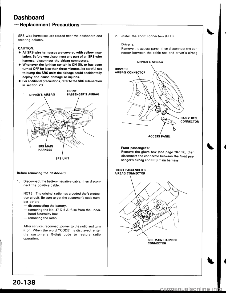
SRS wire harnesses are routed near the dashboard and
steenng column.
CAUTION:
a All SRS wire hsrnesses are covered wiih yellow insu-
lation. Before you disconnect any pan of an SRS wire
harness, disconnect the airbag conneclors.
a Whenever the ignition switch is ON (ll), or has been
tulned OFF for less than three minules, be careful not
to bump the SRS unit; the ai.bags could accidentally
deploy and cause damage or injuries.
a For additional precautions, refer lo the SRS sub-section
in section 23.
PASSENGER'S AIRBAG
Belore removing the dashboard:
1. Disconnect the battery negative cable, then discon-ne.r rhe n^.iriua.ahla
NOTEr The original radio has a coded thett protec,
tion circuit. Be sure to get the customer's code num
ber before- disconnecting the battery.- removing the No. 47 (7.5 A) fuse from the under-
hood tuse/relay box.- removing the radio.
After service, reconnect power to the radio and turn
it on. When the word "CODE" is displayed, enter
the customer's 5-digit code to restore radio
operation.
DRIVER'S AIRBAG
SRS UNIT
20-138
2.Install the short connectors (RED).
Driver's:
Remove the access panel, then disconnect the con-
nector between the cable reel and driver's airbag.
CABL€ REELCONNECTOR--_--._-_-----
Front passenger's:
Remove the glove box (see page 20-137), thendisconnect the connector between the front pas-
senger's airbag and SRS main harness.
FRONT PASSENGER'SAIRBAG CONNECTOR
SRS MAIN HARNESSCONNECTOR
ORIVER'S AIRBAG
Page 954 of 1681
Replacement
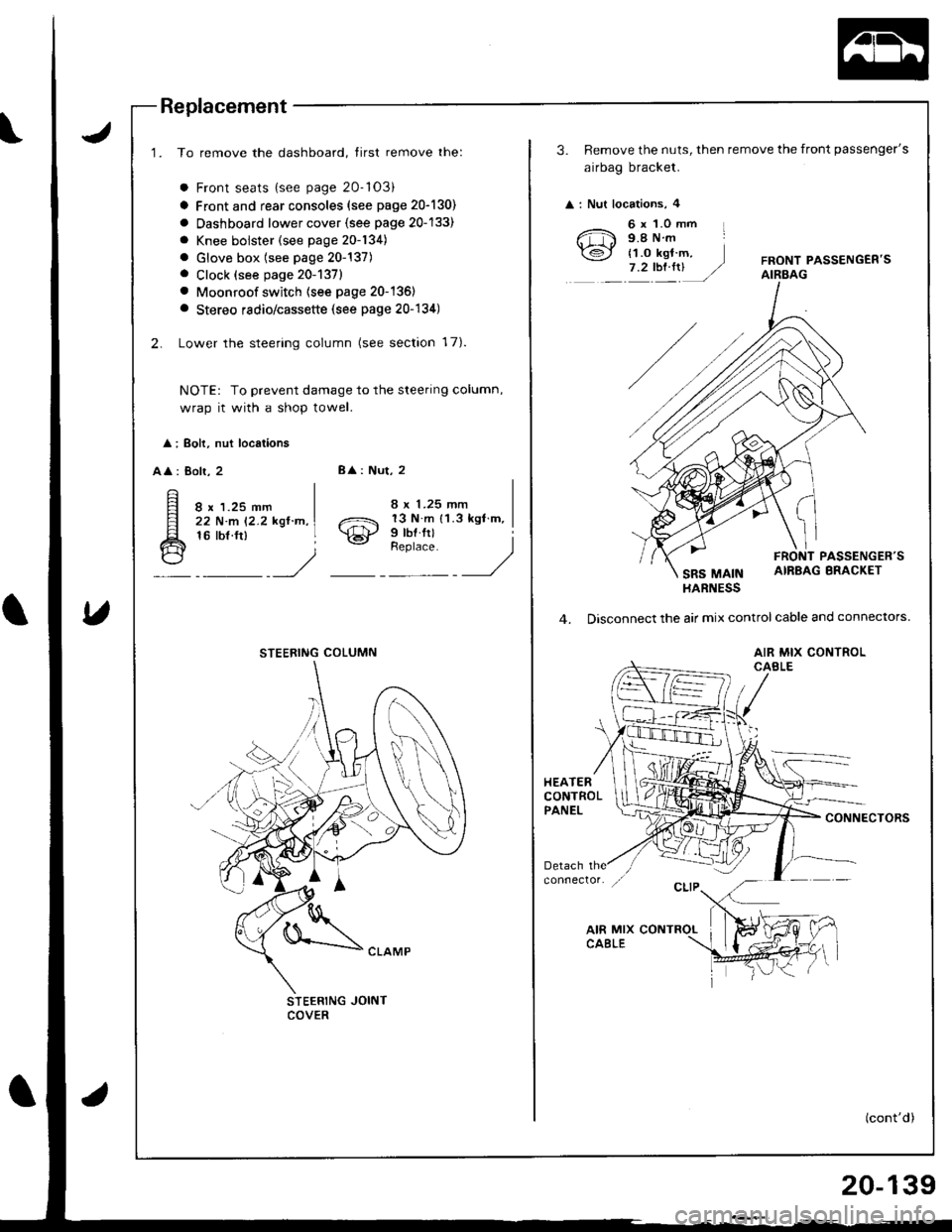
1. To remove the dashboard, tirst remove the:
a Front seats {see page 20-'103)
a Front and rear consoles (see page 20-130)
a Oashboard lower cover {see page 20-133)
a Knee bolster (see page 20-134)
. Glove box (see page 20-137). Clock (see page 20-1371
. Moonroof switch (see page 20-136)
a Stereo radio/cassette (see page 20-134)
2. Lower the steering column (see section 17).
NOTE: To prevent damage to the steering column,
wrap it with a shop towel.
l ; Boh, nut locations
AA : Bolr, 28
: Nut, 2
8 x 1.25 mm22 N.m 12.2 kgl.n,16 tbf.ft)o21 13 N m 11.3 kgl m,
\€J' Prbl rll
_Urr'rr,t __)
STEERING JOINTCOVER
STEERING COLUMN
3. Remove the nuts, then remove the front passenger's
airbag bracket.
: Nut locations, 4
6 x 1.0 mm L9.8Nm
{1.o kgt m,7.2tbt.rrUFRONT PASSENGEB'SAIRBAG
PASSENGER'S
SRS MAINAIRBAG BRACKET
HARNESS
4. Disconnect the air mix control cable and connectors.
AIR MIX CONTROLCABLE
HEATERCONTROLPANELCONNECTORS
(cont'd)
20-139
Page 955 of 1681
Dashboard
6.
Replacement (cont'dl
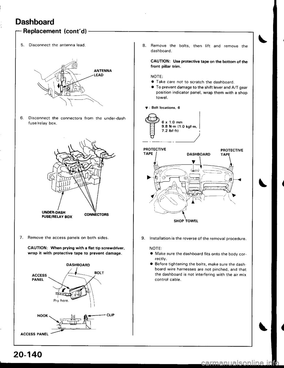
5. Disconnect the antenna lead.
Disconnect the connectors from the under-dash
fuse/relay box.
7.Remove the access panels on both sides.
CAUTION: When pfying with a tlat tip screwdrivel,
wrap it with protective tape to prevent damage.
ACCESSPANEL
HOOK H R<-- cLlP -- tfit\z-:E--4l_l
L__\L
lccPss pltlteL /
DASHBOARD
20-140
8. Remove the bolts, then lift and remove the
dashboard.
CAUTION: Use protective tape on the bottom of thefront pillar trim.
NOTE:
a Take care not to scratch the dashboard.
a To prevent damage to the shift lever and A/T gear
position indicator panel, wrap them with a shop
rowet.
V: Eolt localions, 6
6 x 1.0 mm9.8 N.m {1.0 kgf m,7 .2 ,hl.ltl
9. Installation is the reverse of the removal procedure.
NOTE:
a Make sure the dashboard fits onto the body cor,rec y.
a Before tightening the bolts, make sure the dashboard wire harnesses are not pinched, and that
the dashboard is not interfering with the air mix
control cable.
SHOP TOWEL
Page 966 of 1681
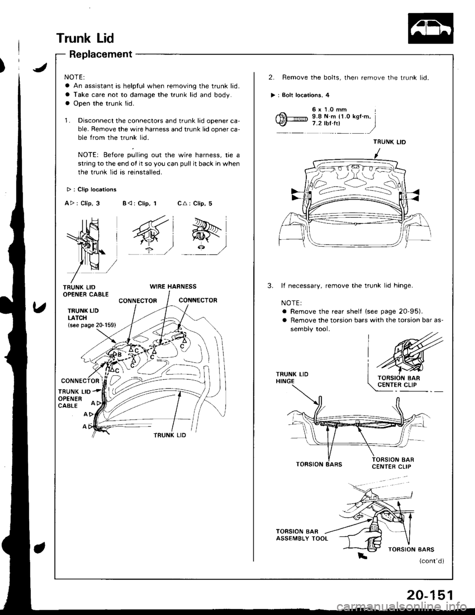
Trunk Lid
NOTE:
a An assistant is helpful when removing the trunk lid.
a Take care not to damage the t.unk lid and body.
a Open the trunk lid.
1. Disconnect the connectors and trunk lid opener ca'
ble. Remove the wire harness and trunk lid opner ca-
ble from the trunk lid.
NOTE: Before pulling out the wire harness, tie a
strang to the end ot it so you can pull it back in when
the trunk lid is reinstalled.
2. Remove the bolts, then remove the trunk lid.
> : Bolt locaiions, 4
6x LOmm
6!--'.'.'''* 9.8 N.m n.o ksf .m. l\
A> : Clip, 3B< : Clip, 1
4*i
wj?,/
CA : Clip, 5
&qr/
TRUNK LIDOPENER CAELE
TRUNK LIDLATCH(see page 20-1591
WIRE HARNESS3.lf necessary, remove the trunk lid hinge.
NOTE:
a Remove the rear shelt {see page 20-95).
CONNECTORCONNECTOR
a Remove the torsion bars with the torsion bar as-
sembly tool.
TRUNK LIDHINGE
TRUNK LIDOPENERCABLE
A
TRUNK LID
TORSION
(cont'd )
TRUNK LID
Replacement
20-151
Page 969 of 1681

6h*")
Opener Cables
Replacement
NOTE:\
a When removing the clips, use a clip remover.
a Take care not to bend the opener cables.
Hood Opener Cable:
V : Clip locations
AV:Clip,5
>: Scraw localions, 8
M)
6h* |" _,/
NOTE: Loosen the screw, then removethe clrp using a clip remover,
Fuel Lid Opcner Cables lHatchback):
NOTE: Remove the rea r seat (see page 20-1 l0), rea r trim pa nel and side trim panel (see page 20-91), then pull the carpet
back, as necessary (see page 20-126J.
A: Clip, cablo cushion location3
A A: Clip, 1 I A: Clip,6
FUEL LIO LATCH(see page 20-157)
) \,)
-----d,
FUEL LID
\
HOOD OPENER
20-154
Page 970 of 1681
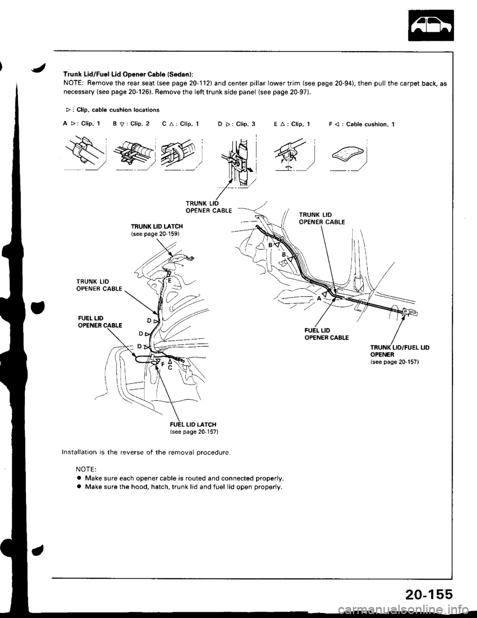
Trunk Lid/Fuel Lid Opener Cable (Sedan):
NOTE: Remove the rear seat (see page 20-1'l2l and center pillar lower trim (see page 20-94), then pull the carpet back, as
necessary {see page 20-126). Remove the left trunk side panel (see page 20-97).
C a: Clip, 1E A: Clip, 1D >: Clip, 3
w-l
)tQ,,
r-
> : Clip. cabl6 cushion locations
A >: Clip, 1 B V: Clip, 2
Qs , r>>.
lww-
F < | Cable cushion, 1
6t
ei
TRUNK LID LATCH(see page 20'159)
(see page 20,157)
Installation is the reverse of the removal procedure.
NOTE:
a Make sure each opener cable is routed and connected properly.
a Make sure the hood, hatch, trunk lid and fuel lid open properly.
OPENER(see page 20-157)
20-155
Page 971 of 1681
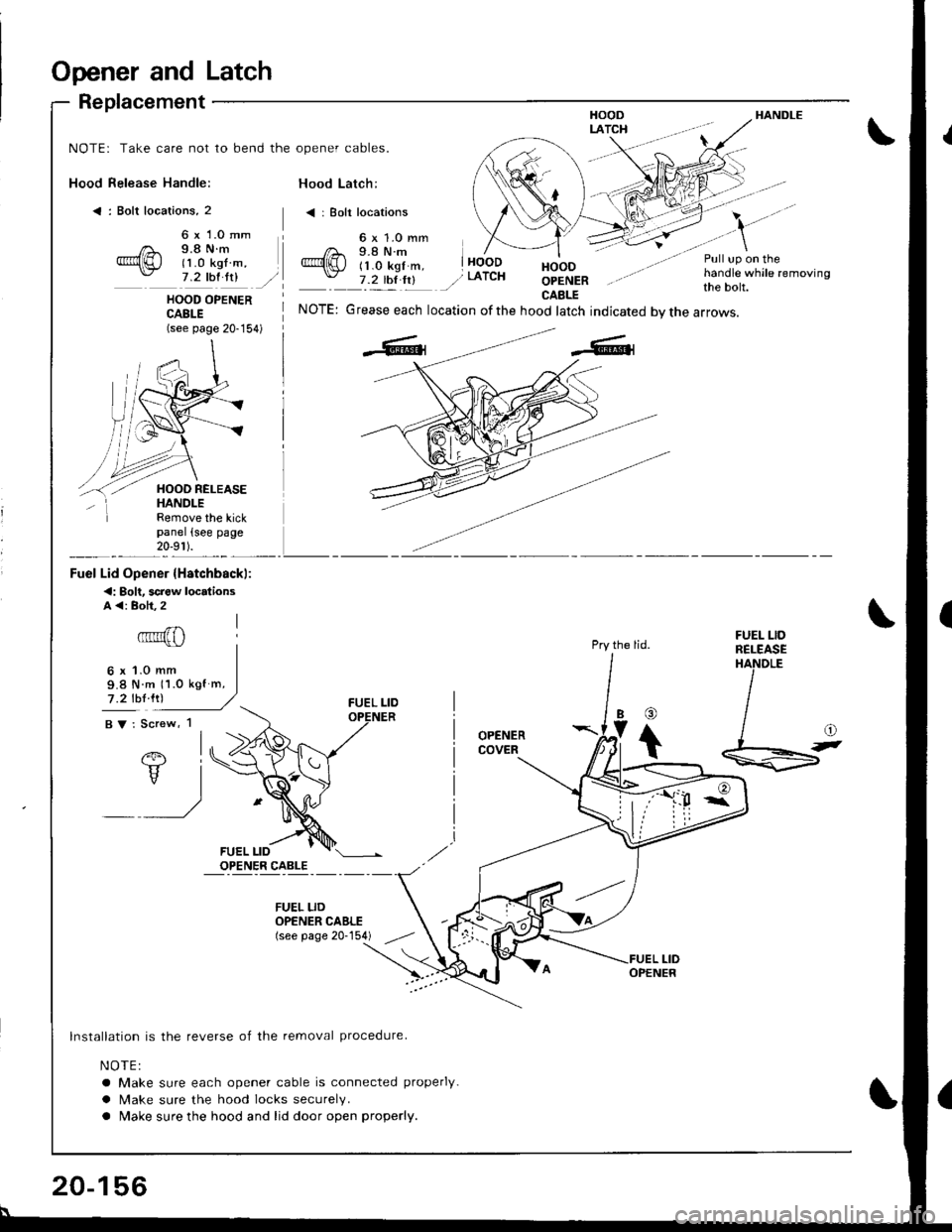
Opener and Latch
Replacement
Hood Release Handle:
< : Bolt locations, 2
HANDLE
NOTE: Take care not to bend the opener cables.
Hood Latch:
< | Bolt locations
6 x 1.0 mm9.8 N.m(1 .0 kgf m,7 .2 thl ltlHOODOPENERCAELE
Pull up on thehandle while removingthe bolt.HOOD OPENERCABLE(see page 20-154)
NOTE: Grease each location ofthe hood latch indicated bvthe arrows.
Pry the lid.
OPENERCOVER
Remove the kickpanel (see page20-9r ).
Fuel Lid Opener {Hstchbackl:
<: Bolt. screw locdionsA <: Boh.2
6x1.0mm9.8 N m 11.0 kgf m,
7 .2 lbl lrl
BV: Screw, 1
FUEL LIDRELEASEHANDLE
@
Ib
t
lnstallation is the reverse of the removal procedure.
NOTE:
a Make sure each opener cable is connected properly.
a Make sure the hood locks securely.
a Make sure the hood and lid door open properly.
FUEL LIDOPENER CAELE(see page 20-154)
20-156
Page 972 of 1681
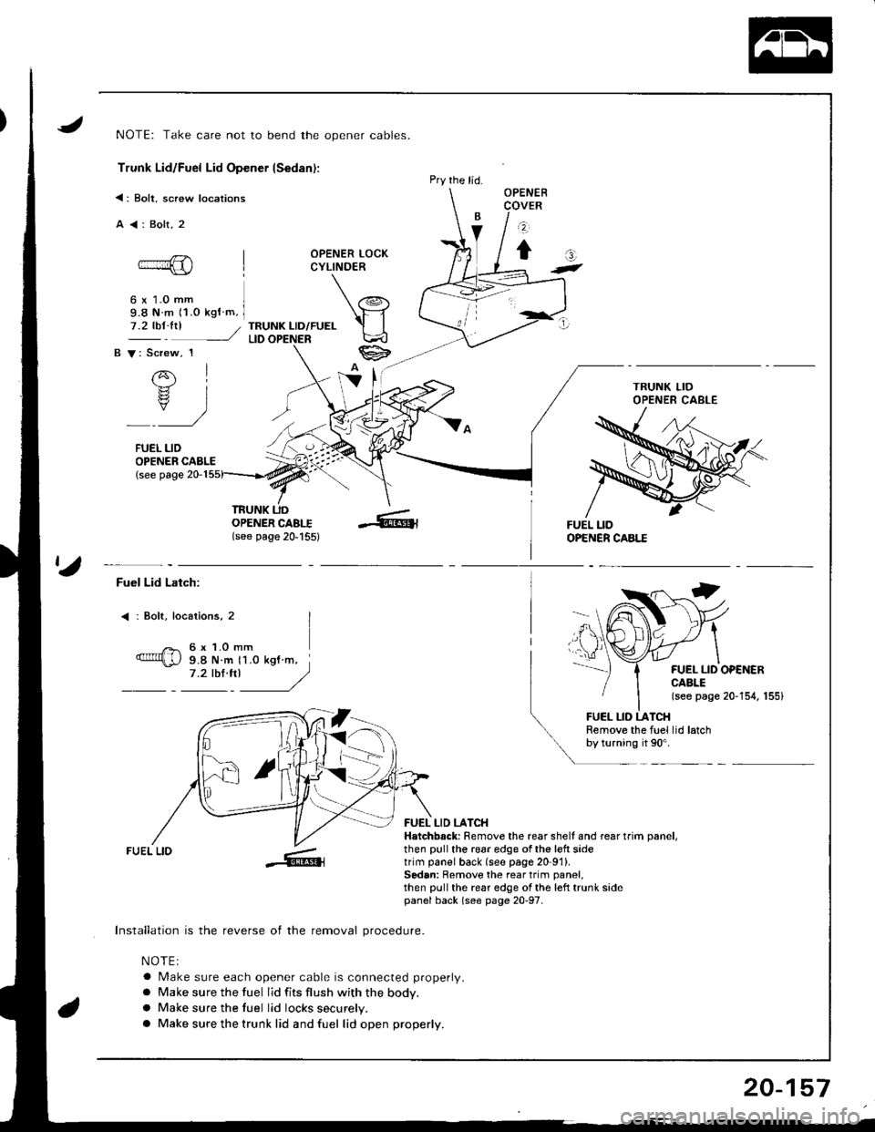
NOTE: Take care not to bend the opener cables.
Trunk Lid/Fuel Lid Opener lSedan):
<: Bolt, screw locations
A<:Bolt,2
OPENER LOCKCYLINDER
6 x 1.0 mm9.8 N m 11.o kgf m,
TRUNK LID/FUELLID
OPENER CABLE{see page 20-1
OPENERCOVER
z
tat-
7.2 tbt.trl /
B V: Screw, 1
rql.b.rz
rs? IY)
FUEL LID
TRUNK UDOPENER CABI.I(see page 20'155)
Pry the lid.
ta
Fuel Lid Latch:
: Bolt, locaiions, 2
6 x 1.O mm9.8 N.m 11.0 kgt m,7.2 tbl.trl J/)
FUEL LID OPEiIERCABLE(see page 20-154, 155)
FUEL LID LATCHRemove the fuel lid latchby turning it 90'.
FUEL LIO
Installation is the reverse of the removal procedure.
NOTEI
a Make sure each opener cable is connected properly.
a Make sure the fuel lid fits flush with the body.
a Make sure the tuel lid locks securely.
a Make sure the trunk lid and fuel lid open properly.
FUEL LID LATCHHatchbsck: Remove the rear shell and rear trim oanel,then pull the 196r edge of the left sidetrim panel back (see page 20-91).Sedan: Remove the rear trim panel,then pull the rear edge ol the left trunk sidepanel back (s€e page 20-97.
20-157
Page 974 of 1681
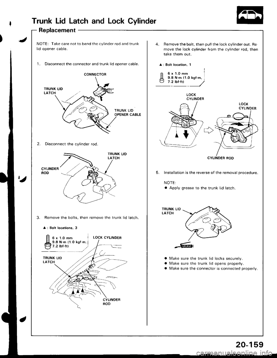
Trunk Lid Latch and Lock Cylinder
Replacement
JNOTE: Take care not to bend the cylinder rod and trunk
lid opener cable.
1. Disconnect the connector and trunk lid opener cable.
4. Remove the bolt, then pull the lock cylinder out. Re
move the lock cylinder {rom the cylinder rod, then
take them out.
: Bolt location, 1
CONNECIOR
LOCKCYLINDER
r>'
2. Disconnect the cylinder rod.
CYLINDERROD
CYLINOER ROD
5. lnstallation is the reverse of the removal procedure.
NOTE:
a Apply grease to the trunk lid latch.
Remove the bolts, then remove the trunk lid
: Boli locations, 3
TRUNK LIDLATCH
3.latch.
6x1.0mm ILOCK CYLINDER
9.8 N.m 11.0 kgf m, I
:t"r': -/
a
a
a
Make sure the trunk lid locks securely.
N/ake sure the trunk lid opens properly.
Make sure the connector is connected properly.
20-159