cable HONDA INTEGRA 1998 4.G Owner's Guide
[x] Cancel search | Manufacturer: HONDA, Model Year: 1998, Model line: INTEGRA, Model: HONDA INTEGRA 1998 4.GPages: 1681, PDF Size: 54.22 MB
Page 595 of 1681
Throttle Control Cable
Inspection
NOTE: Before inspecting the throttle controlcable, makesure:
a Throttle cable tree play is correct (see section I 1).a ldle speed is correct (see section 1l).a To warm up the engine to normal operating tempera-
ture (the cooling fan comes on).
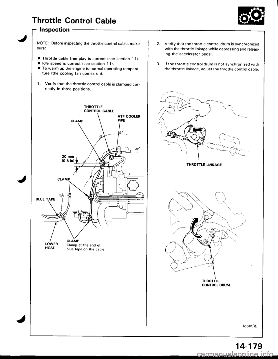
1 . Verify that the throttle control cable is clamped cor-rectly in three positions.
CONTROL CABLE
LOWERHOSEClamp at the end ofblue tape on the cable.
Verily that the throttle controldrum is synchronized
with the throttle linkage while depressing and releas-
ing the accelerator pedal.
ll the throttle control drum is not synchronized with
the throttle linkage, adjust rhe throttle control cable.
(cont'd)
14-179
Page 596 of 1681
Throttle Control Cable
lnspection (cont'd)
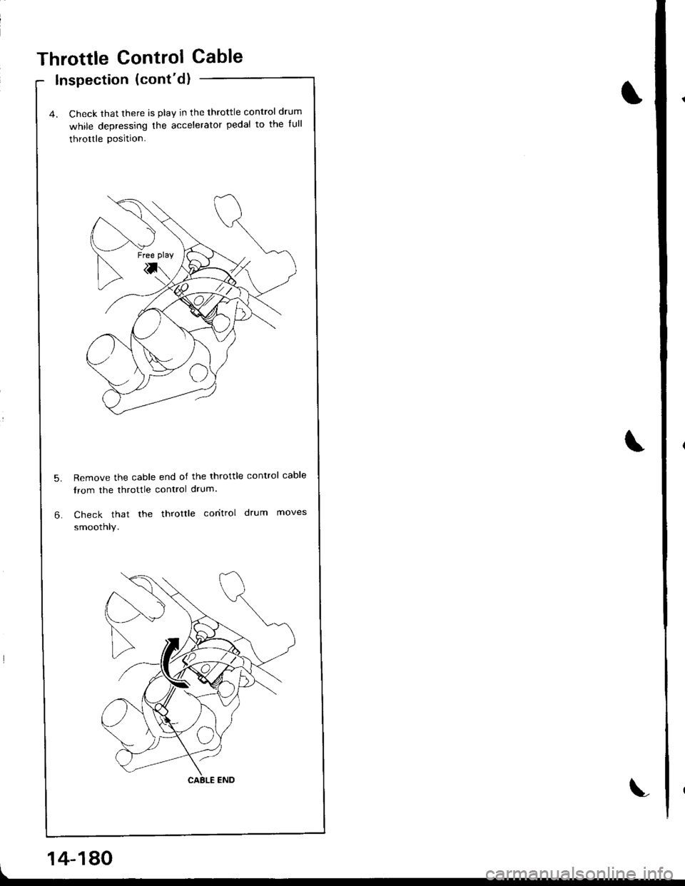
4. Check that there is play in the throttle control drum
while depressing the accelerator pedal to the full
throttle position.
Remove the cable end of the throttle control cable
from the throttle control drum.
Check that the throttle coritrol drum moves
smoothly.
\
14-180
Page 597 of 1681
Adjustment
NOTE: Before adjusting the throttle controlcable, make
sure:
a Throttle cable lree play is correct (see section 11).a ldle speed is correct (see section 11).a To warm up the engine to normal operating tempera-
ture {the cooling fan comes on)
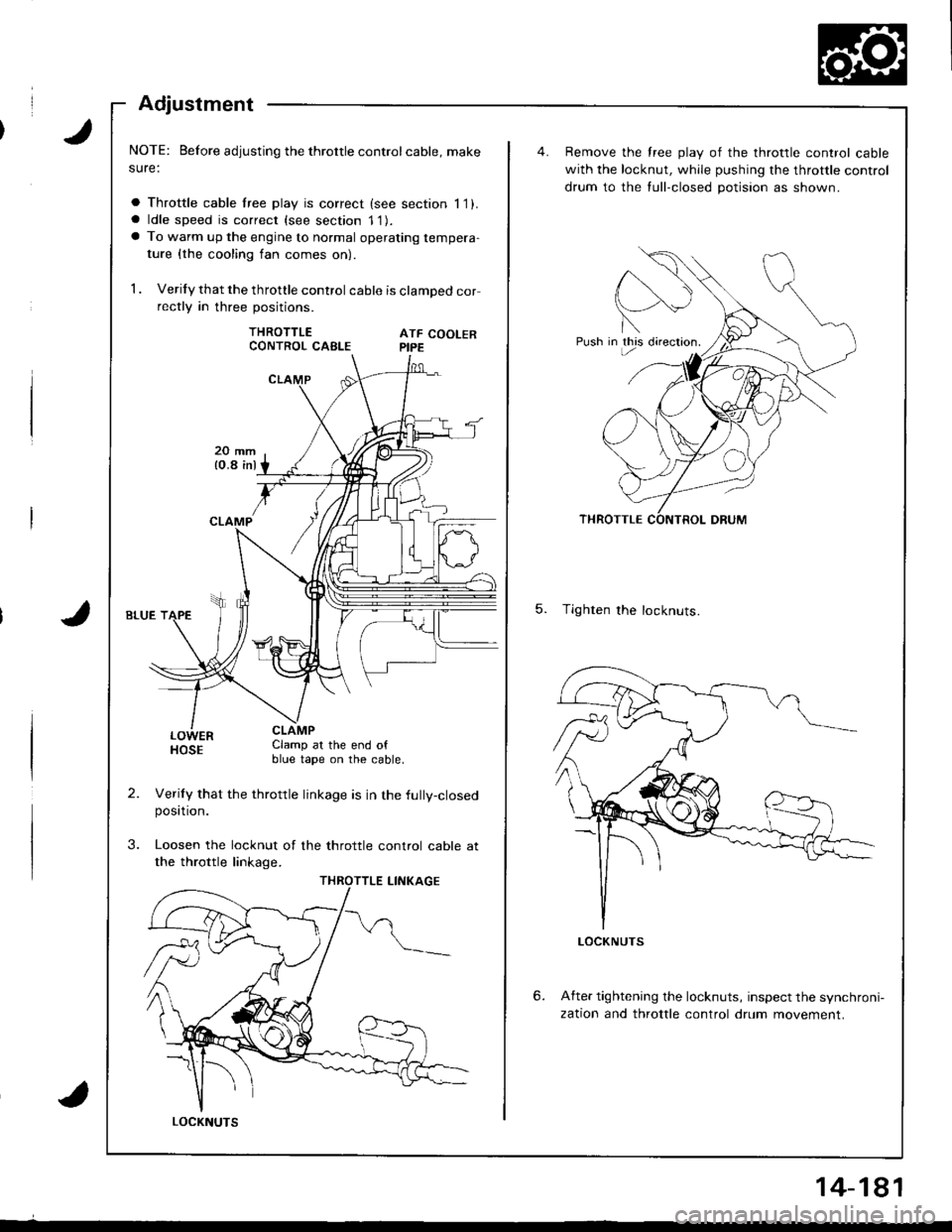
1 . Verify that the throttle control cable is clamped correctly in three positions.
THROTTLEATF COOLERPIPE
LOWERHOSEClamp at the end ofblue tape on the cable.
Verily that the throttle linkage is in the fully-closedposttron.
Loosen the locknut of the throttle control cable at
the throttle linkage.
CONTROL CABLE
LOCKNUTS
14-181
Push in this directron.
Remove the free play of the throttle control cable
with the locknut, while pushing the throttle control
drum to the tull-closed potision as shown.
5. Tighten the locknuts.
6.After tightening the locknuts, inspect the synchroni-
zation and throttle control drum movement.
Page 673 of 1681
Steering Wheel
Removal
Airbag Removal
'CAUTION:
. All SRS wiro harne33e3 ar€ coverad with yellow insu.
lation. Beforo you di3connect Eny part of En SRS
wiro harn6ss, disconnsct the airbag conncctors.
. Whenaver ths ignition switch is ON {ll}, or ha3 b.cn
turned OFF lor l.3s than thrcc minuto3, be cErs{ul
not to bump th6 SRS unh; the airbags could rcciden-
tally deploy and cause damsgo or iniurias'
. Fo. additional preclution3, rofer to tho SRS sub-soc'
tion in 36ction 23,
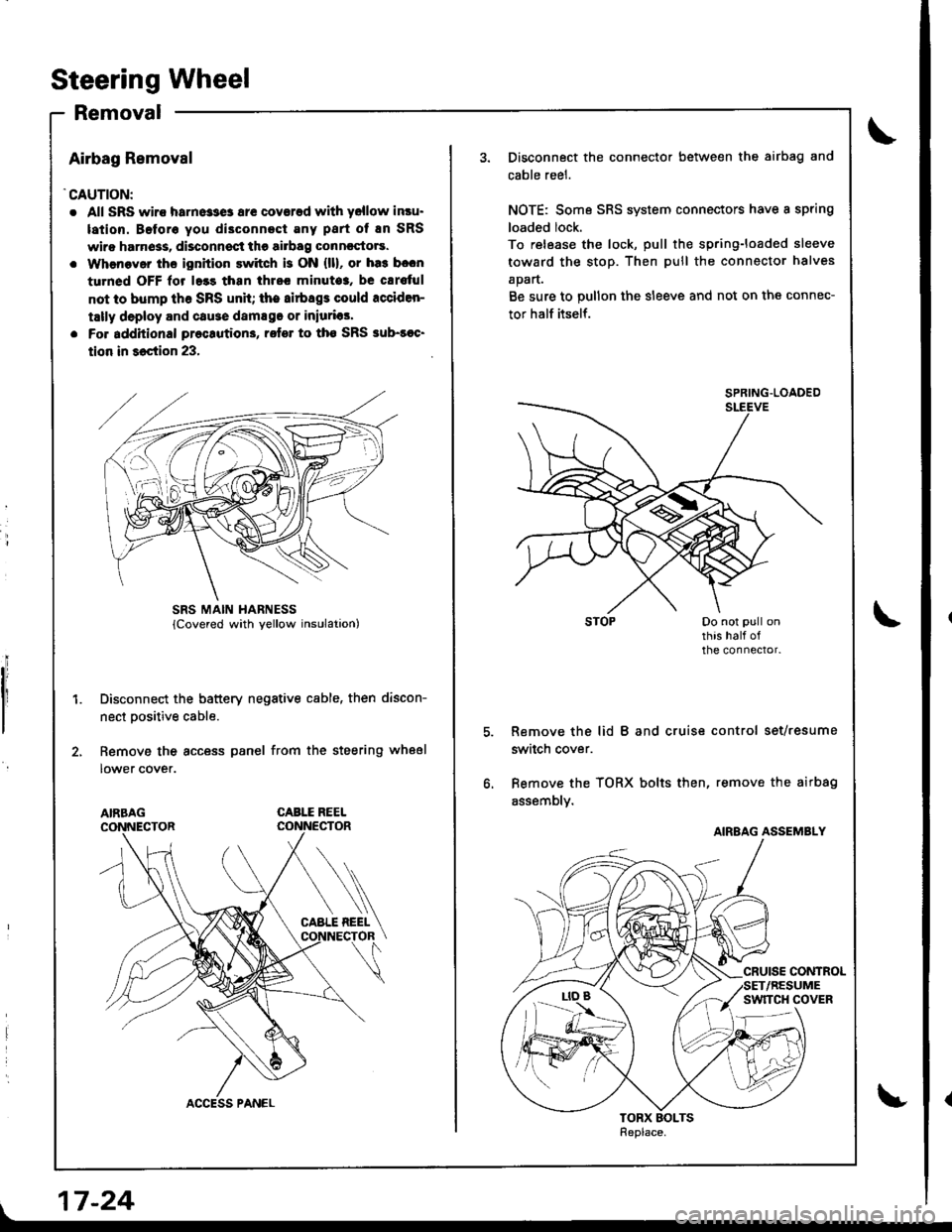
Disconnect the battery negative cable, then discon-
nect Dositive cable.
Remove the access panel from the steering wheel
lower cover.
CABLE REEL
L
SRS MAIN HARNESS
17-24
Disconnect the connector between the airbag and
cable reel.
NOTE: Some SRS system connectors have a spring
loaded lock.
To release the lock, pull the spring-loaded sleeve
toward the stop. Then pull the connector halves
apart.
Be sure to pullon the sleeve and not on the connec-
tor half itself.
Remove the lid B and cruise control set/resume
switch cover.
Bemove the TORX bolts then, remove the airbag
assembly.
SPRING.LOADED
AIRBAG ASSEMBLY
Page 675 of 1681
Steering Wheel
lnstallation
Airbag installation
CAUTION:
. Before installing ths st€€ring wheel, align th€ front
wheels straight ahead.
. Be sure to ingtall the harnoss wirss 90 that they 8re
not pinched or intorfering with other car parts.
. Do not replace the original st€ering wheel with rny
other d8ign, since it will mako h impossiblo to p.op-
erly install the sirbag. {Only use genuinc HONDA
rephcamont parts)
. After rea$embly, contirm that ih€ wheels are still
st.ight 8head and that stooring wheel spoke angle
is correct. It minor spoko aogle sdiustment is n€cas-
sary. do so only by adiustment ol the tis-rods, not by
removing and reposhioning the 3teering who€|.
!@ confirm thst the airbag a33embly is
sscurely attached to th€ steering wheel; otherwi3e,
severe personal iniury could result during airbag
deploymenl.
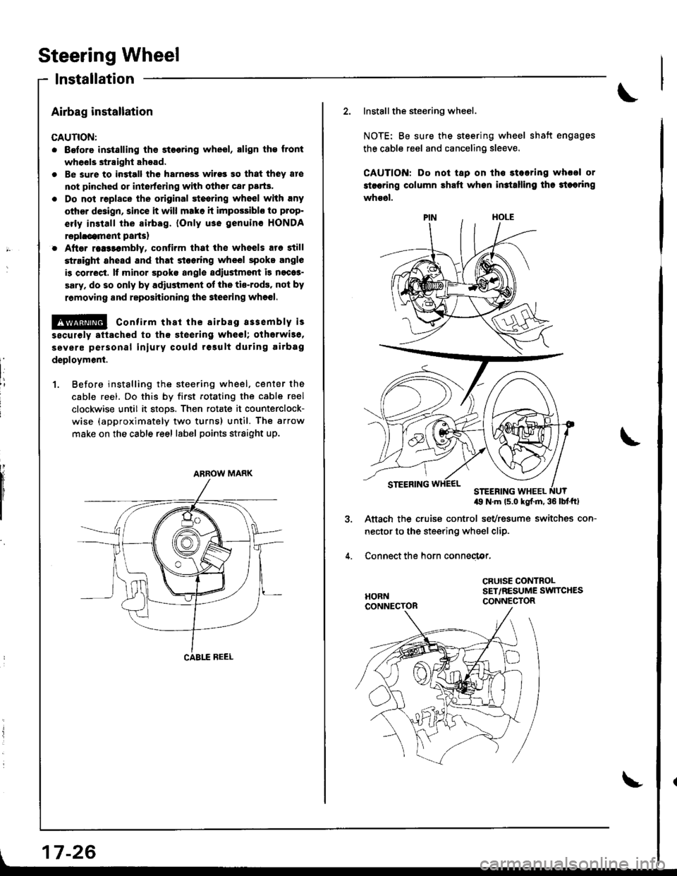
1. Before instslling the steering wheel. center the
cable reel. Do this by first rotating the cable reel
clockwise until it stoos. Then rotate it counterclock-
wise (approximately two turns) until. The arrow
make on the cable reel label points straight up.
ARROW MARK
| 17-26
\
2. Installthe steering wheel.
NOTE: Be sure the steering wheel shatt engages
the cable reel and canceling sleeve.
CAUTION: Do not tap on ths stearing whool or
stsering column shaft whon in3tslling tha 3teoring
whs6l.
49 N'm ls.o kgf.m. 36 lbf'ftl
Aftach the cruise control sevresume switches con-
nector to the steering wheel clip.
Connect the horn conneclor,
CRUISE CONTROLSET,/RESUME SW]TCHESCONNECTOR
Page 676 of 1681
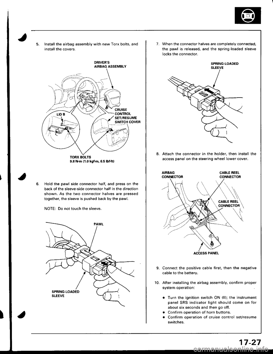
Installthe airbag assembly with new Torx bolts, and
installthe covers.
cRursECONTROLSET/RESUMEswtTcH covER
Hold the pawl side connector half. and press on the
back of the sleeve-side connector halt in the direction
shown. As the two connector halves are pressed
together, the sleeve is pushed back by the pawl.
NOTE: Do not touch the sleeve.
7.When the connector halves are completely connected.
the pawl is released. and the spring loaded sleeve
locks the connector.
SPRING.LOADEDSLEEVE
Attach the connector in the holder, then install the
access panel on the stee.ing wheel lower cover.
Connect the positive cable first. then the negative
cable to the battery.
After installing the airbag assembly, confirm proper
system operation:
. Turn the ignition switch ON (ll); the instrument
panel SRS indicator light should come on for
about six seconds and then go off.
. Confirm operation of horn buttons.
. Confirm operation of cruise control sevresume
switches.
10.
17-27
Page 677 of 1681
Steering Golumn
Removal
I
a All SRS wire harnesses are covered with yellow insu-
lation. Before vou disconnect any pan of an SRS wire
harness, disconnect the airbag Gonnectors.
a Whenever the ignition switch is ON (lll, or has been
turned OFF for less than three minutes, be carelul not
to bump the SRS unit; the airbags could accidentally
deploy and cause damage or iniuries.
a For additional precautions, lelel to the SRS sub-section
in section 23.
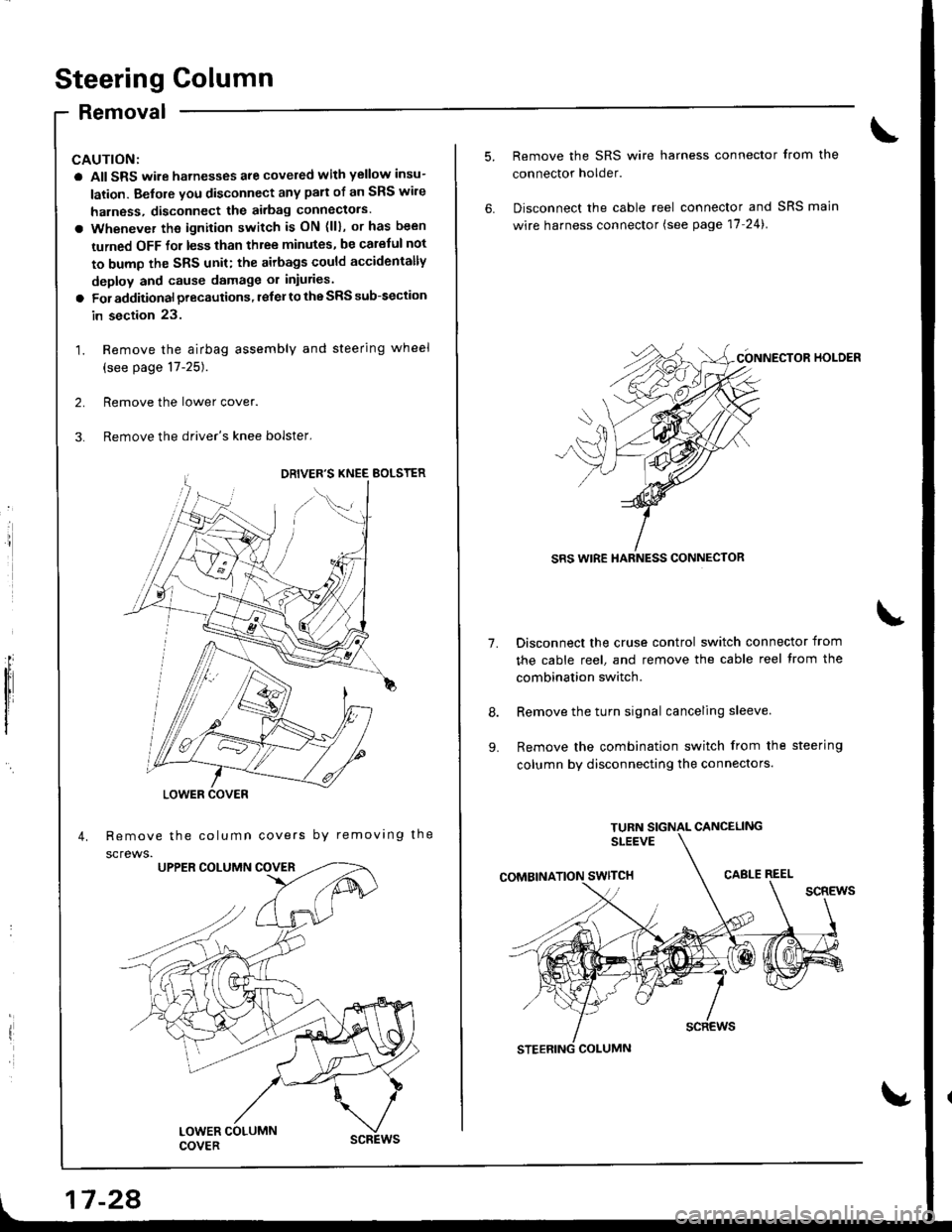
1. Remove the airbag assembly and steering wheel
(see page 17-25).
2. Remove the lower cover.
3. Remove the driver's knee bolster,
Remove the column covers by removing the
screws.
'//
,,1G
LOWER COVER
17 -28
1.
9.
Remove the SRS wire harness connector from the
connector holder.
Disconnect the cable reel connector and SRS main
wire harness connector (see page 17-24).
CONNECTOR HOI-DER
SRS WIRE HARNESS CONNECTOR
Disconnect the cruse control switch connector from
the cable reel, and remove the cable reel trom the
combination switch.
Remove the turn signal canceling sleeve.
Remove the combination switch from the steering
column by disconnecting the connectors.
Page 682 of 1681
9.
1.
8.
11.
10.
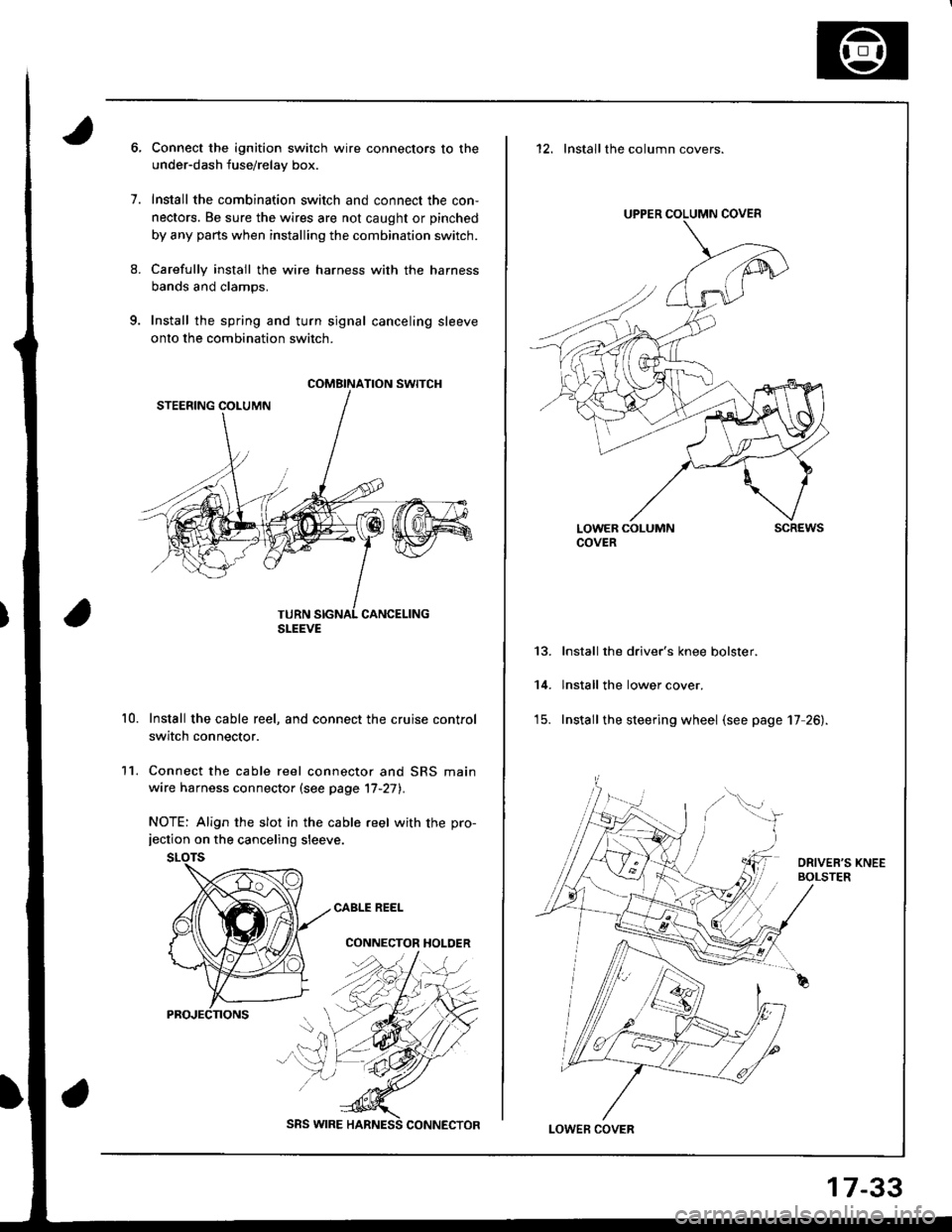
Connect the ignition switch wire connectors to the
under-dash fuse/relay box.
Install the combination switch and connect the con,
nectors. Be sure the wires are not caught or pinched
by any parts when installing the combination switch.
Carefully install the wire harness with the harness
bands and clamps.
Install the spring and turn signal canceling sleeve
onto the combination switch.
Install the cable reel, and connect the cruise control
switch connector.
Connect the cable reel connector and SRS main
wire harness connector (see page '17-27).
NOTE: Align the slot in the cable reel with the pro-jection on the canceling sleeve.
CABLE REEL
CONNECTOR HOLDER
COMBINATION SWITCH
SLEEVE
SRS WIRE
17-33
12. Installthe column covers.
UPPER COLUMN COVER
LOWER COLUMNCOVERscREws
13.
14.
Install the driver's knee bolster.
lnstall the lower cover.
Install the steering wheel (see page 17 26).
LOWEF COVER
Page 708 of 1681
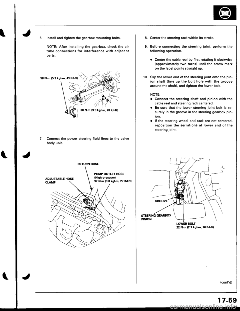
Install and tighten the gearbox mounting bolts.
NOTE: After installing the gearbox, check the air
tube connections for interference with adjacent
parts.
58 N.m 15.9 kgl.m, 43 lbf.ftl
Connect the power steering fluid lines to the valve
body unit.
7.
38 N.m {3.9 kgt m, 28 lbf.ftl
RETURN HOSE
PUMP OUTI.TY HOSE(High-pressure)
37 N.m (3.8 kgf.m, 27 lbt.ftl
Center the steering rack within its stroke.
Before connecting the steering joint, perform the
lollowing operation.
. Center the cable reel by first rotating it clockwise(approximately two turns) until the arrow mark
on the label points straight up,
Slip the lower end of the steering ioint onto the pin-
ion shaft {line up the bolt hole with the groove
around the shaft), and tighten the lower bolt.
NOTE:
. Connect the steering shaft and pinion with the
cable reel and steering rack centered.
. Be sure that the lower steering joint bolt is se-
curely in the groove in the steering gearbox pin-
ion.
o lf the steering wheel and rack are not centered,
reoosition the serrations at lower end of the
steering joint.
(cont'd)
LOWER BOLT22 N.m {2.2 kgf.m, 16 lbf.ft,
17-59
Page 755 of 1681
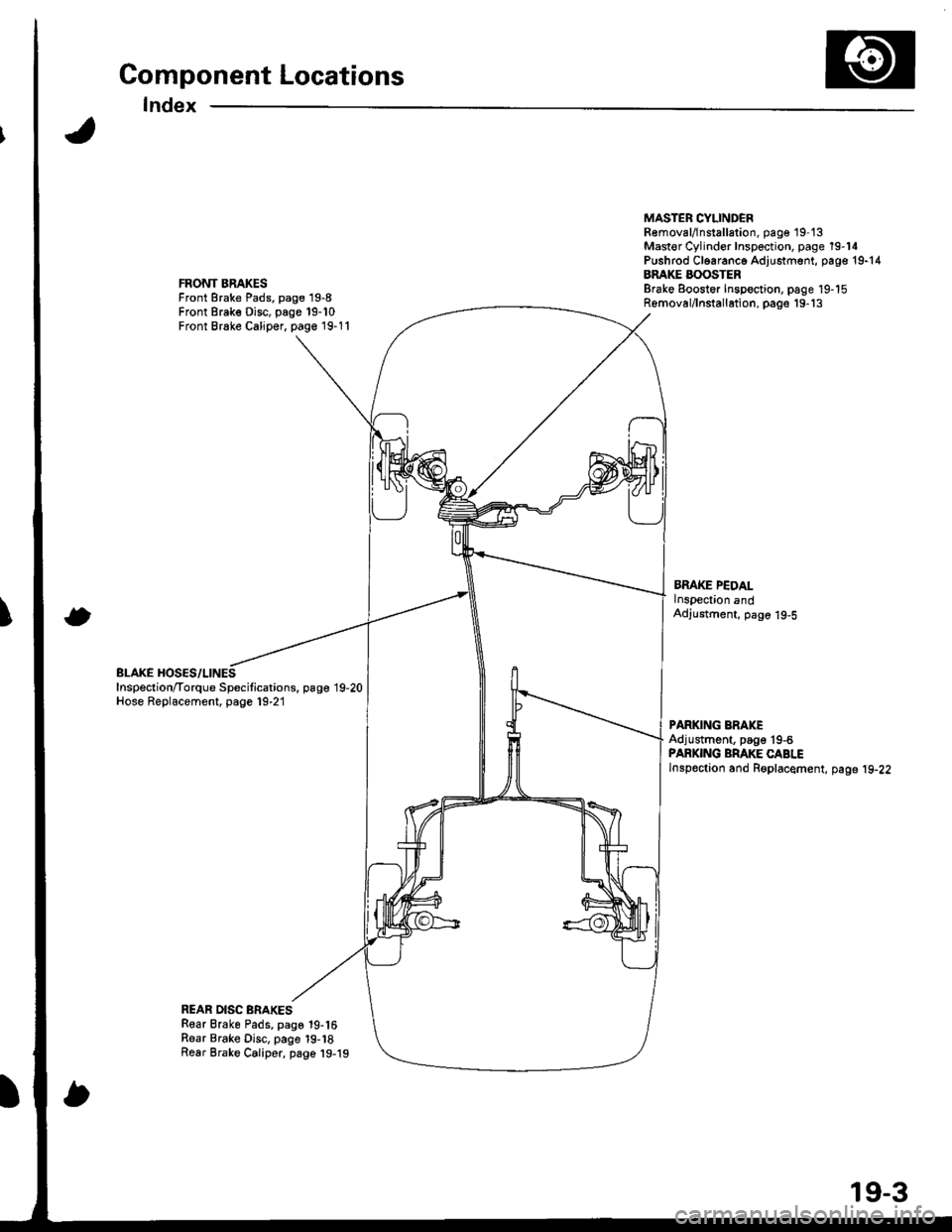
Component Locations
Index
FRONT BRAKESFront Brake Pads, page 19-8Front Brake Disc, page 19-10Front Brake Caliper, page 19-11
BLAKE HOSES/LINESInspection/Torque Specitications. page 19,20Hose Replacement, page 19-21
MASTER CYLINDEBR€moval/lnstallation, pag€ 19-'t3Mast€r Cylinder Inspection, page 19-14Pushrod Cl6aranc6 Adjustment, page 19-14BRAKE BOOSTERBrake Eoostor Inspoction, page 19-15Removal/lnstallation, pags'19-'13
BMKE PEDALlnspection andAdjustment, page 19-5
PARKING ERAKEAdjustment, page'19-6PARKING BRAKE CABLElnspoction and Roplacement, page 19-22
REAR DISC BRAKESRear Brake Pads, page 19-16Rear Brake Disc, page 19-18Rear Brake Caliper, page 19-19
19-3