light HONDA INTEGRA 1998 4.G User Guide
[x] Cancel search | Manufacturer: HONDA, Model Year: 1998, Model line: INTEGRA, Model: HONDA INTEGRA 1998 4.GPages: 1681, PDF Size: 54.22 MB
Page 219 of 1681
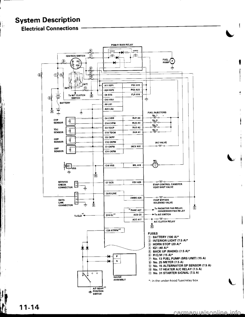
System DescriPtion
Electrical Connections
FUELIN'ECTOHS
EVAP COIiTIBOL CANISTEAvE|rISHUT VAIVE
sotENoto vaLvE
lo FAOIAIOB FAN FELAY,CONOEI{SEh FAN FELAY
FUSESr-1) BATTERY {100 A)*
€) INTERIOF LIGHT {7.5 A}.
€) HORN STOP 120 A)'
o rcl (,$ A)*
o BACK UP IRADIO) 17.5 A)*
@ Fr €/M t15 Al'.'I NO. .I3 FUEL PUMP ISRS UNIN (15 A)
a,J No. 25 METER 17.5 Al
O No. 15 ALTERNATOR SP SENSOR {7.5 A}(0 No. 17 HEATER A/C R€LAY (7.5 A)(i) No. 31 STAnTEB SIGNAL (7.5 A)
*: in the under'hood fuse/relaY box
Page 240 of 1681
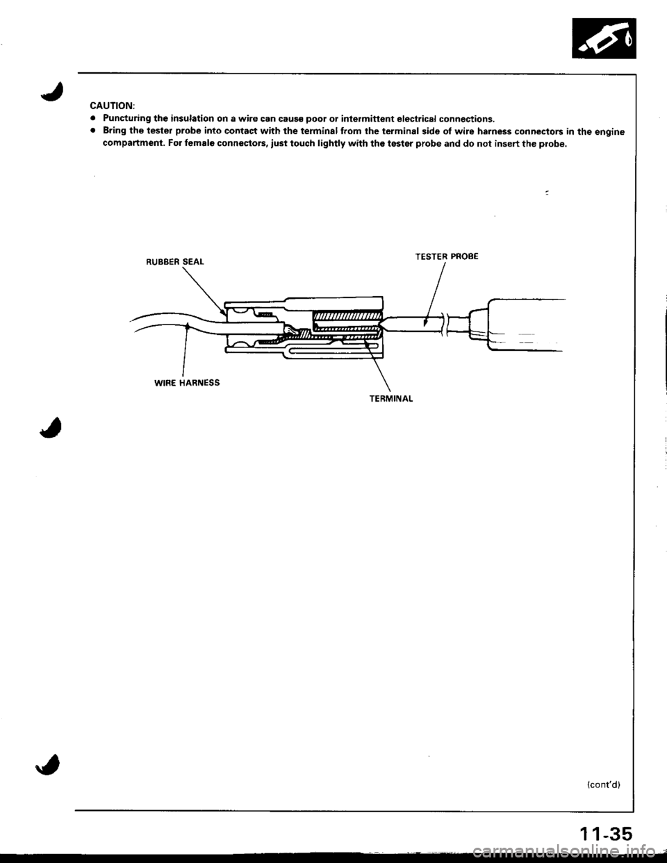
CAUTION:
. Puncturing th€ insulation on a wire can caus€ poot ot inlermitlent electrical connections.. Bring tho tester probe into contact with the terminalffom the tcrminal side of wire harness connectors in the engine
compartment. For female connestors, iust touch lightly with the tsster probe and do not insert the probe.
TESTER PROB€
(cont'd)
TERMINAL
11-35
Page 246 of 1681
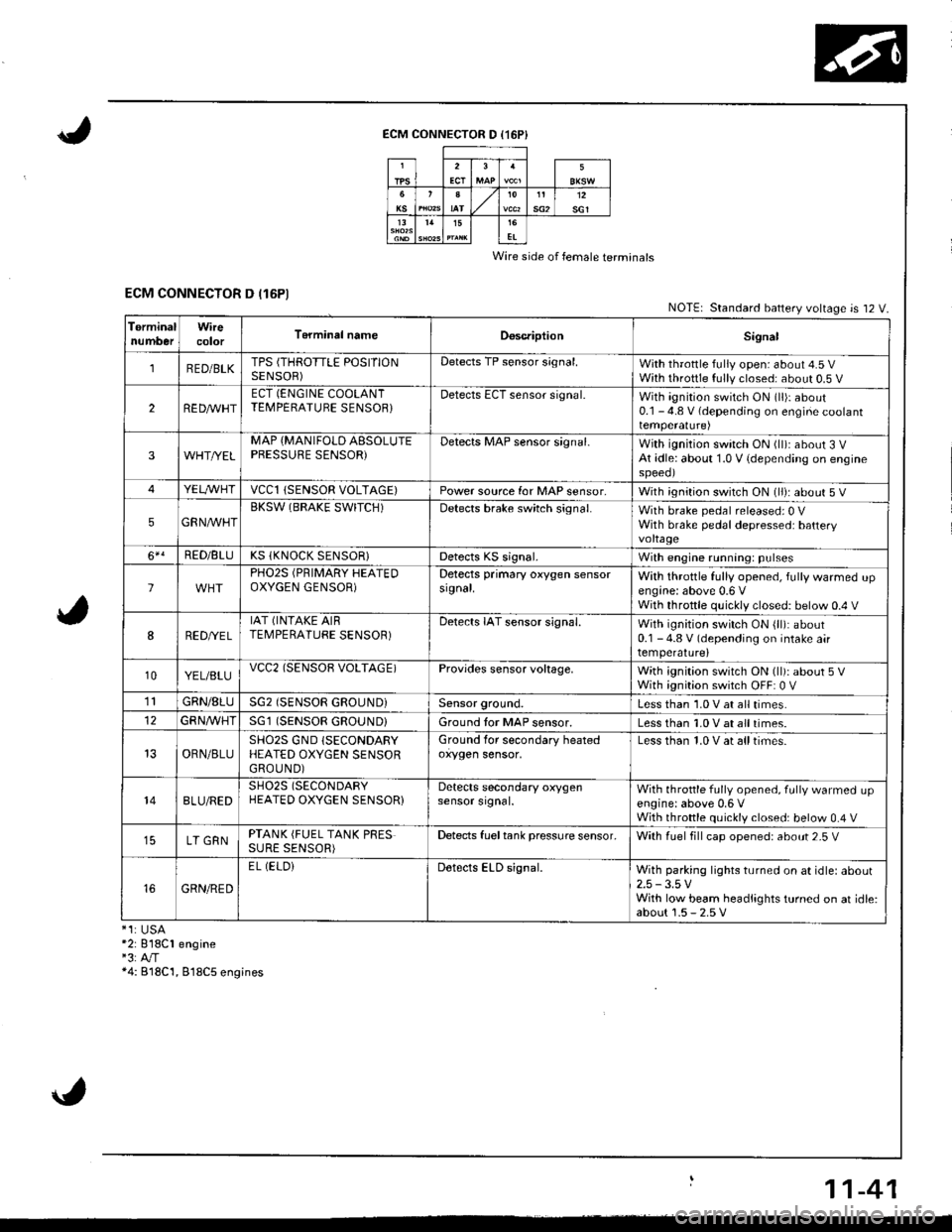
ECM CONNECTOR D (16P}
Wire side of female terminals
ECM CONNECTOR D (16P1NOTE| Standard battery voltage is 12 V.
TerminalnumberWirecolorT6rminal nameDoscriptionSignal
1RED/BLKTPS (THROTTLE POSITIONSENSOR)Detects TP sensor s;gnal.With throttle fully open: about 4.5 VWith throttle fully closed: about 0.5 V
2REDAr'r'HTECT (ENGINE COOLANTTEMPERATUBE SENSOB}Detects ECT sensor signal.With ignition switch ON (ll)r about0.1 - 4.8 V (depending on engine coolanttemperalure)
3WHT//ELMAP {MANIFOLD AESOLUTEPBESSURE SENSOR)Detects MAP sensor signal.With ignition switch ON (ll)iabout 3 VAt idle: about 1.0 V {depending on enginespeeol
4YELA/VHTvccl{SENSOR VOLTAGE)Power source for MAP sensor,With ignition switch ON (ll): about 5 V
5GRNAVHTBKSW (BRAKE SWITCH)Detects brake switch signal.With brake pedal released: 0 VWith brake pedal depressed: batteryvoltage
6*!RED/BLUKS (KNOCK SENSOR}Detects KS signal.With engine running: pulses
lPHO2S (PRIMARY HEATEDOXYGEN GENSOR)Detects primary oxygen sensorsignal.With throttle fully opened, fully warmed upengine: above 0.6 VWith throttle quickly closed: below 0.4 V
8RED/VEL
IAT (INTAKE AIRTEMPERATURE SENSOR)Detects IAT sensor signal.With ignition switch ON {ll): about0.1 - 4.8 V (depending on intake airtemperature)
10YEL/BLUvcc2(SENSOB VOLTAGE)Provides sensor voltage,With ignition switch ON (ll): about 5 VWith ignition switch OFF: 0 V
1lGRN/8LUSG2 (SENSOR GROUND}Sensor ground.Less than 1.0 V at all times.
GFNA/VHT(SENSOR GROUND}Ground tor MAP sensor.Less than 1.0 V at all times.
OBN/BLUSHO2S GND (SECONDARY
HEATED OXYGEN SENSORGROUND)
Ground for secondary heatedoxygen sensor,Less than 1.0 V at alltimes.
148LU/REDSH02S (SECONDARY
HEATED OXYGEN SENSOR}Detects secondary oxygensensor srgnal.With throttle fully opened. fully warmed upengine: above 0,6 VWith throttle quickly closed: below 0.4 V
LT GRNPTANK (FUEL TANK PRESSURE SENSOR)Detects fueltank pressure sensor.With luel fill cap opened: about 2-5 V
GRN/RED
EL (ELOiDetects ELD signal.With parking lights turned on at idle: about2.5 -3.5 VWith low beam headlights turned on at idle:about 1.5 - 2.5 V*1:USA*2: 818C1 engine"3:A"/T*4: B18C'1, 818C5 engines
11-41
Page 254 of 1681
3.Fuel Cut-off Control
. Du ring dece leration with the th rottle va lve closed, cu rrent to the fuel injectors is cutoffto improvefuel economyat
speeds over following rpm:. B'1881 engine: 970 rpm {Canada model: 1.050 rpm). B18C1 engine:970 rpm {Canada model: 1.050 rpm). 818C5 engine: 1,300 rpm (Canada model: 1,400 rpm)
. Fuel cut-off action also takes place when engine speed exceeds 7,000 rpm (B'1881 engine), 8.100 rpm (818C1
engine) or 8,600 rpm (818C5 engine), regardless ol the position of the thronle valve, to protect the engine from
over-revving.
A,,/C ComDressor Clutch Relav
When the ECM receives a demand for cooling from the air conditioning system, it delays the compressor from being
energized, and enriches the mixture to assure smooth transition to the A,/C mode.
Evaporative Emission (EVAP) Purge Control Solenoid Valve
When the engine coolanl temperature is above '154'F (68'C) and the air conditioner on. the ECM controls the EVAPpurge control solenoid valve which controls vacuum to the EVAP purge control canister.
Intake Air Eypass (lAB) Control Solenoid Valve*a
When the engine rpm is below 5,750 rpm, rhe IAB control solenoid valve is activated by a signal from the ECM, intake
air flows through the long intake path, then high torque is delivered. At speeds higher than 5,750 rpm, the solenoidvalve is deactivated by the ECM, and intake air flows through the short intake path in order to reduce the resistance in
airflow.
Sell-diagnosis Function lMalfunction Indicator Lamp {MlL)lWhen an abnormality occurs in a signal from a sensor, the ECM supplies ground for the MIL and stores the code in
erasable memory. When the ignition is initially turned on, the ECM supplies ground for the N4lL tor two seconds to
check the MIL bulb condition.
Two Driving Cycle Detection Method
To prevent false indications, the Two Driving Cycle Detection Method is used for the HO2S, fuel metering-related, idle
control system, ECT sensor, TWC and EVAP control system and other self-diagnostic functions, When an abnormality
occurs, the ECM stores it in its memory. When the same abnormality recurs after the ignition switch is turned OFFand ON (ll)again, the ECM informs the driver by lighting the MlL.
However, to ease troubleshooting, this function is cancelled when you shon the service check connector. The MIL will
then blink immediately when an abnormality occurs.
4.
5.
6.
3.
4.
ECM Fail-safe/8ack.up F0nctions
1. Fail-sate Function
When an abnormality occurs in a signal from a sensor, the ECM ignores that signal and assumes a pre-programmed
value for that sensor that allows the enqine to continue to run.
2. Back-uo Function
When an abnormality occurs in the ECM itself, the fuel injectors are controlled by a back-up circuit independent of the
system in order to permit minimal driving.
11-49
Page 255 of 1681
I
I
It:
PGM-FI System
Engine Control Module {ECMI
,i
I
{
ili
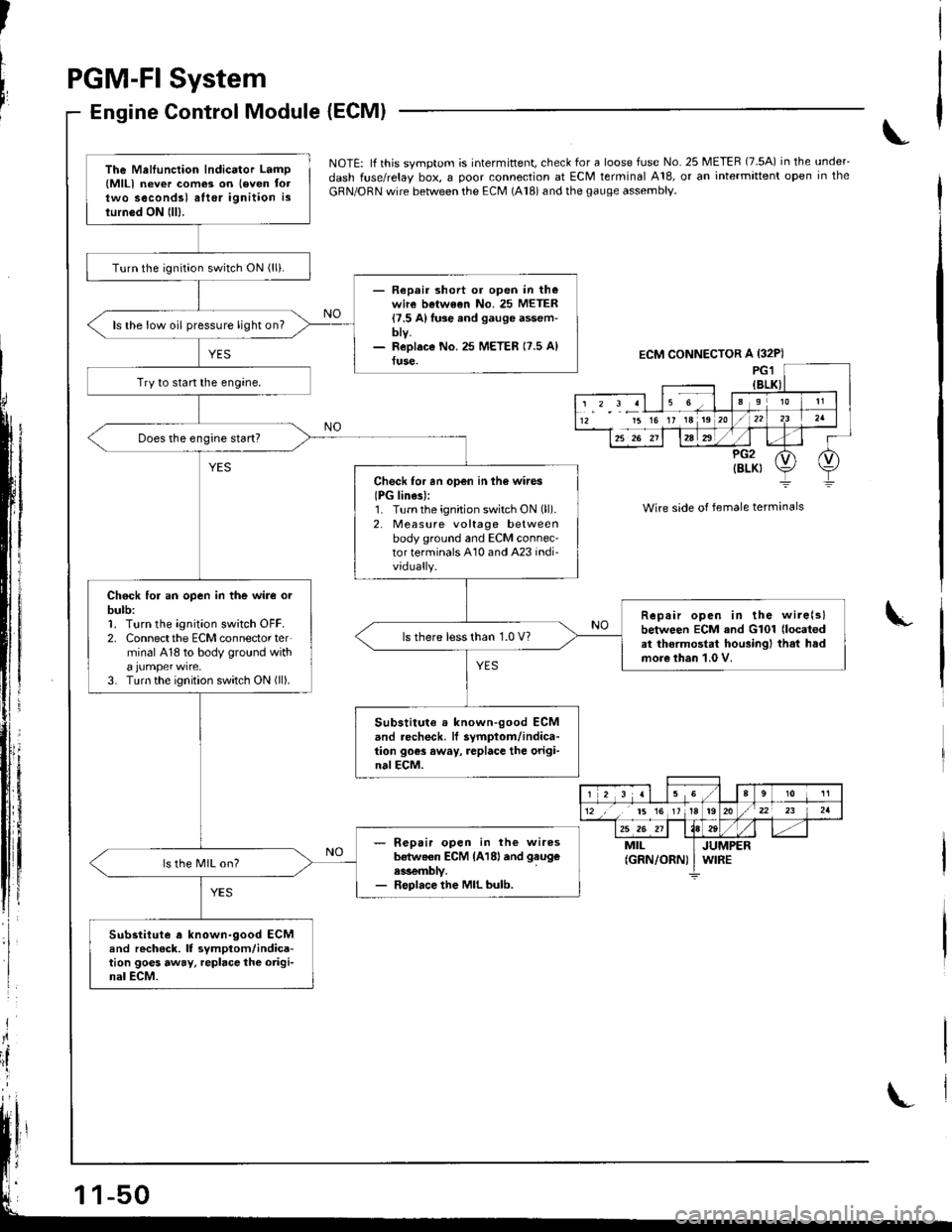
NOTE: lf this svmotom is intermittent, check for a loose fuse No. 25 METER (7.5A) in the under_
dash fuse/relay box, a ooor connection at ECM terminal A18, or an intermittent open in the
GRN/ORN wire between the ECM (A18) and the gauge assembly.
Wire side of female terminals
I
The Mellunction Indicator Lamp(MlLl never com€3 on leven foltwo secondsl alter ignition islurn6d ON lll).
Turn the ignition switch ON (lli.
- Repair short or open in th€wire betwe€n No. 25 METER{7.5 A}fuse and gauge assem-bty.- ReDlaco No.25 METER 17.5 A)fuse.
ls the low oil pressure light on?
Try to start the engine,
Check for an open in ih6 wires
IPG lines):1. Turnthe ignition switch ON (ll).
2. Measure voltage betweenbody ground and ECM connec-tor terminals A10 and A23 indi-vidually.
Chock for an open in the wire orbulb:1. Turn the ignition sw;tch OFF.2. Connectthe ECM connector terminal 418 to body ground with
3. Turn the ignition switch ON (ll).
Repair open in the wire(slbetween ECM and G101 (located
at thermostat housingl that hadmore than 1.0 V.
ls there less than 1.0 V?
Substitute . known-good ECMand .echeck, lf symptom/indica-tion goes away, replace the origi-nalECM.
- R€pair open in the wiresb€tweon ECM {A18land gaug€
ess€mbly.- Replace the MIL bulb.
ls the MIL on?
Substitute a known-9ood ECMand rech6ck. It symptom/indica-tion goes away, repbce the origi-nal ECM.
ECM CONNECTOR A {32P)
15 16 17 18 19
r 2 3 al 15 Ga910 11
12 ,, t5 16 1tt920/22 23 2a
25 26 211184tt-MILJUMPER(GRN/ORN) I WIRE
Page 257 of 1681
PGM.FISystem
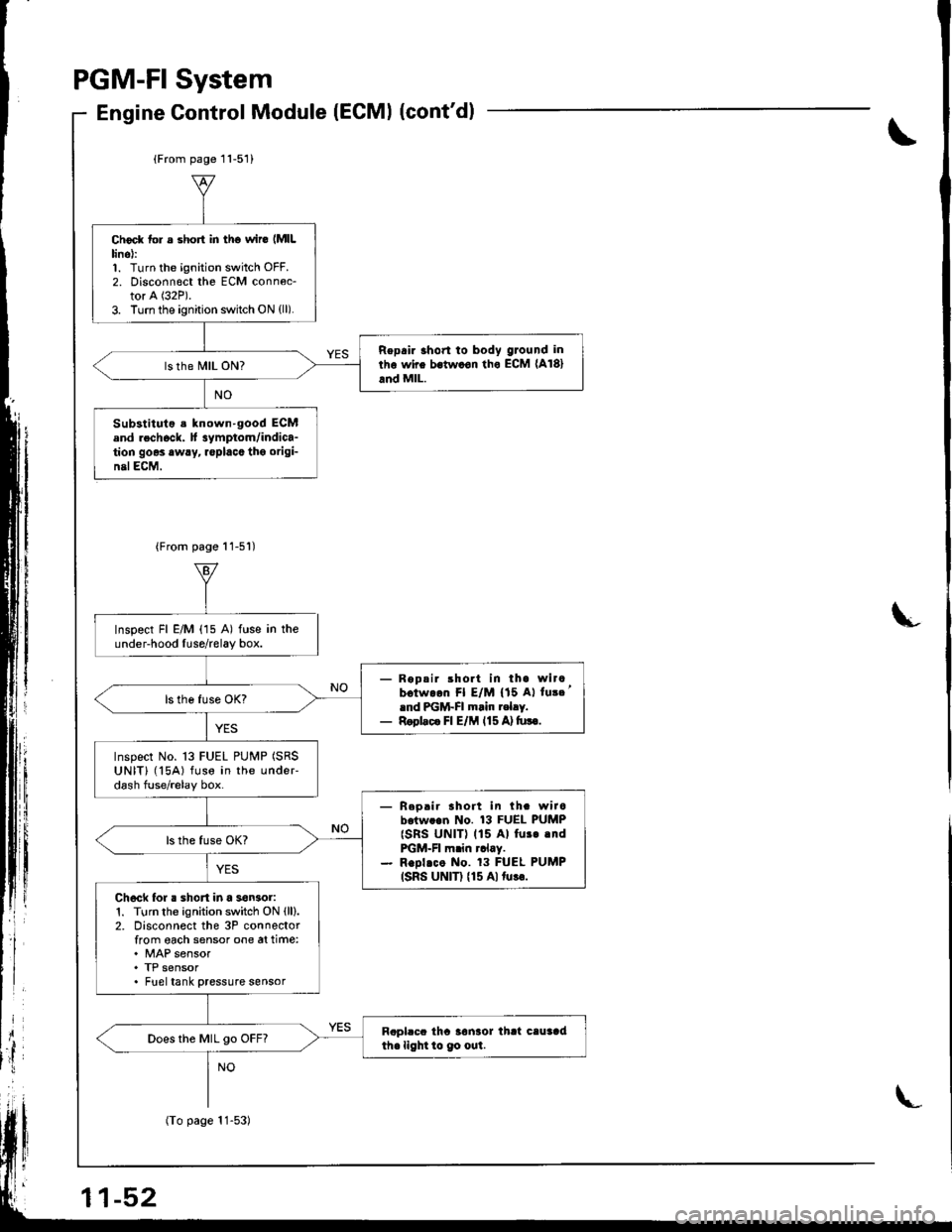
Gontrol Module (ECMI (cont'dlEngine
\
L
(From page 11-51)
Choc* tol s short in tho wir6 lMlLlino):1. Turn the ignition switch OFF.2. Disconn€ct the ECM conn6c-tor A (32P).
3. Turn the ignition switch ON (ll).
Repair 3hon to body ground in
rhe wire bstw.on tho ECM (A181
and MlL.
Substituto s known-good ECMend rechock. H 3ymptom/indica-tion goes awry, replacc tho origi-nelECM,
{From page 11-51)
Inspect Fl E/M (15 A) fuse in theunder-hood Iuse/relay box.
- Ropsir short in tha wircbotw.on Fl E/M {'15 Al tu3c'rnd PGM-FI m.in t.lry.- Rool.c. Fl E/M l15A)tu!€.
Inspect No. 13 FUEL PUMP (SRS
UNIT) ('l5A) fuse in the undeFdash fuse/relay box.
- Reo.ir sholt in th. wirobotw..n No. 13 FUEL PUMP
{SRs UNIT) (15 Al fur..ndFGM-FI m.in rclay.- Repl.co No. 13 FUEL PUMP(SRS UNIT) {15 Alturr.
Ch6ck for . shon in a son3or1. Turn the ignition switch ON (ll).
2. Disconnect the 3P connectorfrom oach sensor one at time:. MAP sensor. TP sensor. Fueltank pressure sensor
Rapl.cc tha 3onaor thrt cauaadihe light to 9o out.Does the MIL go OFF?
1-52
(To page 11-53)
Page 293 of 1681
PGM-FI System
Electrical Load Detector (ELDI (USAI
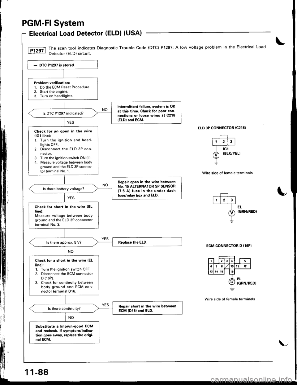
The scan tool indicates Diagnostic Trouble Code (DTC) P1297: A low voltage problem in the Electrical Load
Detector (ELD) circuit.
ELD 3P CONNECTOR {C218)
Wire side of female termin€ls
Problem verification:1- Do the ECM Reset Procedure.2. Stan the engine.3. Turn on headlights.
Int€rmittont failure. swtom b OKat this time. Check tor poor con-neqtions or loose wi.es at C218IELDI and ECM-
ls DTC P1297 indicated?
Check for ao open in the wire
{lG1 linel:1. Turn the ignition and head-lights OFF.2. Disconnect the ELD 3P con-nector,3. Turn the ignition switch ON (ll).
4. Measure voltage betlveen bodyground and the ELD 3P connector te.minal No.'1.
Repair op6n in the wire baiwe€nNo. 15 ALTERNATOR SP SENSOR17.5 Al fus€ in the under-dashluse/relay box and ELD.
Chock lor short in the wire {ELline,:Measure voltage between bodyground and the ELD 3P connectorterminal No.3.
ls there approx. 5 Vl
Check for a short in the wire (EL
linel:1. Turn the ignition switch OFF.2. Disconnect the ECM connectorD (16P).
3. Check for continuity betweenbody ground and ECM con-nector terminal D16.
Sooair short in the wire betweenECM (D161 and ELD.
Substitut€ a known-9ood ECMand recheck. It symptom/indica-tion goes away, r€place the origi-nal ECM.
EL{GRN/REDI
ECM CONNECTOR D {16PI
Wire side oI Iemale tarminals
11-88
Page 294 of 1681
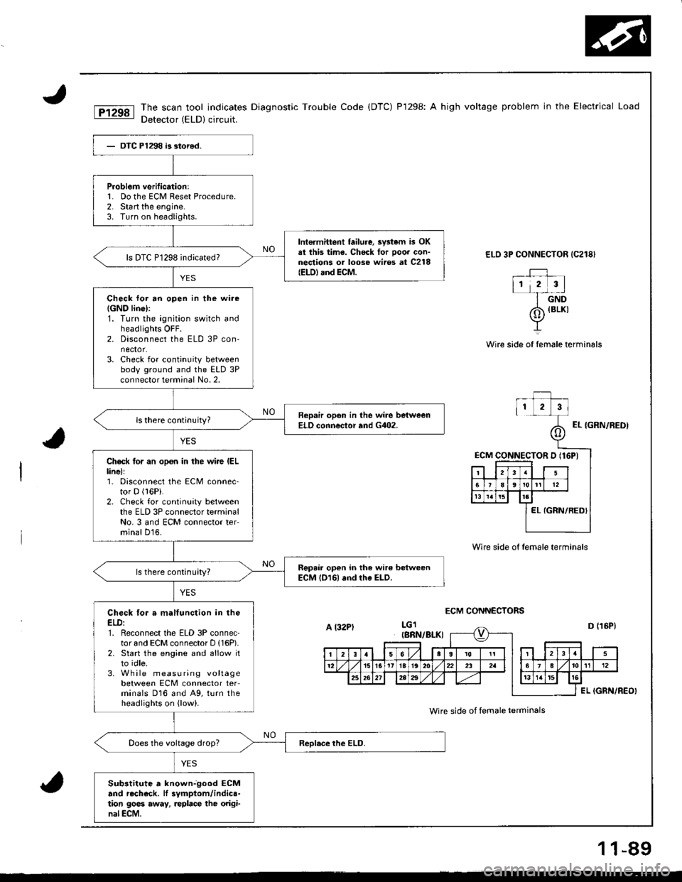
The scan tool indicates Diagnostic Trouble Code (DTC) P1298: A high voltage problem in the Electrical Load
Detector (ELD) circuit.
ELD 3P CONNECTOR {C218}
_rJ ,112 3l-f-dnD
Wire side of female terminals
ECM CONNECTORS
{BLKI
Wire side of female termin6ls
EL {GRN/REDI
ECM CONNECTOR D (16PI
P.oblem verification:l� Do the ECM Reset Procedure.2. Start the engine.3. Turn on headlights.
lntermittent failure, 3vstem is OKel ihis time. Chock for ooor con-nections or loose wiros at C218(EtD) and ECM.
ls DTC P1298 indicated?
Check lor an open in the wire(GNO linel:1. Turn the ignition switch andheadlights OFF.2. Disconnect the ELD 3P con-nector.3. Check for continuity betweenbody ground and the ELD 3Pconnector terminal No. 2.
Bepair opon in the wire bstweenELO connector and G402.
Check tor an opon in the wire IELlinell1. Disconnect the ECM connec-tor D (l6Pi.
2. Check for continuity betweenthe ELD 3P connector terminalNo. 3 and ECM connector terminal D16.
Repair open in the wir€ betweenECM l016l and rhe ELD.ls there continuity?
Check for a malfunction in theELD:1. Reconnect the ELD 3P connec-tor and ECM connector D (16P).
2. Start the engine and allow itto idle.3. Wh ile measuring voltagebetween ECM connector terminals D16 and A9, turn theheadlights on {low).
Sub3titute a knownjgood ECMand rechock. lf 3vmptom/indics-tion 9oe6 away, replace the original ECM.
A l32PtIBRN/BI-KI
Wire side of female ierminals
1 1-89
Page 303 of 1681
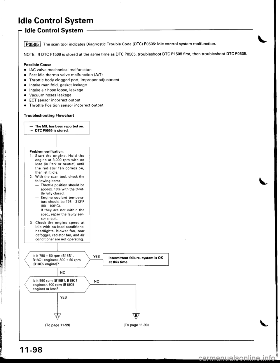
ldle Control System
ldle Control System
i P0505 | fne scan tool indicates Diagnostic Trouble Code (DTC) P0505: ldle control system malfunction,
NOTE: ll DTC Pl508 is stored at the same time as DTC P0505, troubleshoor DTC P1508 first. then troubleshoot DTC P0505.
Possible Cause
. IAC valve mechanical malfunctiorr
. Fast idle thermo valve malfunction (A"/T)
. Throttle body clogged port, improper adjustment
. Intake manifold, gasket leakage
. Intake air hose loose, leakage
a Vacuum hoses leakage
. ECT sensor incorrect output
. Throttle Position sensor incorrect output
Troubleshooting Flowchart
Problem verification:1. Start the engine. Hold theengine at 3,000 rpm wath noload 1in Park or neutral) untilthe radiator fan comes on,then let it idle.2. With the scan tool, check thefollowing items.- Throttle position should beapprox. 10% with the throttle fully closed.Engine coolant tempera-ture should be 116 212F(80 - 100'c).lf they are not within thespec., repair the faulty sensor crrcuft,3 Check the engine speed atidle with no-load conditions:headlights, blower fan, reardefogger, radiator fan, and airconditioner are not operating,
- The MIL has been reported on.- DTC P0505 is stored.
ls it 750 t 50 rpm (81881,
818C1 engines), 800 I 50 rpm(818C5 engine)?
Intermittent failur6, svstsm is OKat this tim€.
ls it 550 rpm (81881,818C1
engines), 600 rpm {818C5enginelor less?
-98
(To page 11'99)(To page 11-99)
Page 306 of 1681
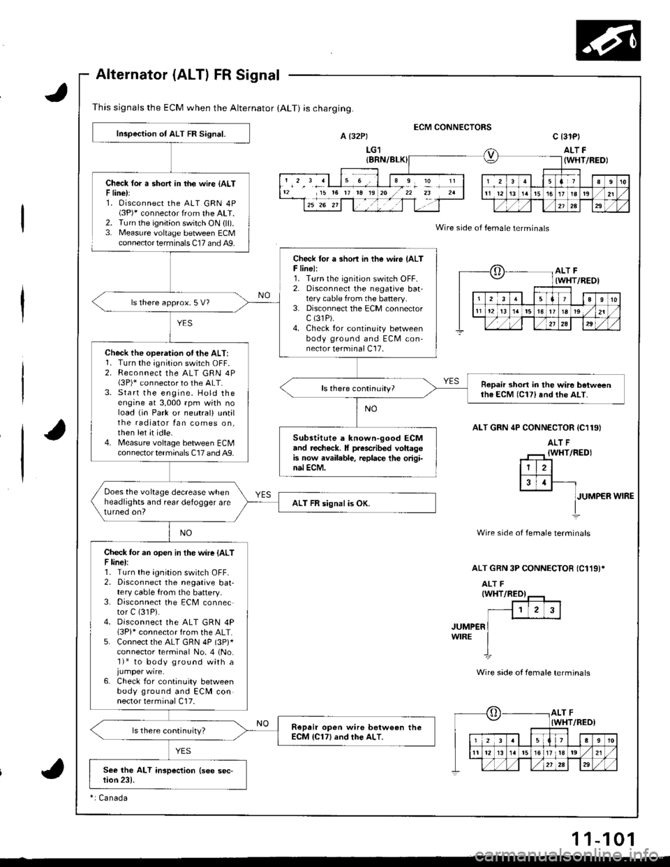
This signals the ECM when the Alternator (ALT) is charging.
Alternator (ALT) FR Signal
Check lor a short in th€ wire {ALTF line):1. Oisconnect the ALT GRN 4P(3P)* connector from the ALT.2. Turn the ignition switch ON {ll).3. Measure voltage between ECMconnector terminals C17 and A9.
ECM CONNECTORSA t32Pt
LG1
c 13lPl
ALT F(WHT/FEDI
Wire side of female terminals
ALT GRN 4P CONN€CTOR {C119}
JUMPER WIRE
Wire side of female terminals
ALT GRN 3P CONNECTOB {C119)*
JUMP€RWIRE
Wire side ot female terminals
12 15 t6 rr t8 19I
?
oALT F(WHT/REOI
23aI10
t112t3t5l6r819 ,/21
./,/,/2a29
[,ALT FIWHT/RED)
12339
11 12l517 tla19 ,/21
Inspection of ALT FR Signal.
Check for a shon in the wire {ALTF line):1. Turn the ignition switch OFF.2. Disconnecl the negative baatery cable from the battery.3. Disconnect the ECM connectorc (31P).
4. Check for continuity betweenbody ground and ECM con-nector terminal C17.
ls there approx.5 V?
Check the operation ofthe ALT:1. Turn the;Onition switch OFF-2. Reconnect the ALT GRN 4P(3P)* connector to the ALT.3. Start the engine. Hold theengine at 3,000 rpm wkh noload {in Park or neutral) untilthe radiator fan comes on,then let it idle.4. Measure voltage bet/veen ECMcon nector termina ls C17 and A9.
Ropair short in the wir6 betweenth6 ECM (C17) and the ALT.
Substitute a known-good ECMand recheck. It prescribed voltagGis now available, replace th€ origi-nal ECM.
Does the voltage decrease whenheadlights and rear defogger areturned on?ALT FR signal is OK.
Check tor an open in the wire {ALTF line):1. Turn the ignition switch OFF-2. Disconnect the negative bat-tery cable from the battery.3. Disconnect the ECM connector C (31P).
4. Disconnect the ALT GRN 4P(3Pi* connector from the ALT.5. Connect the ALT GRN 4P (3p)*
connector terminal No. 4 (No.'l)* to body ground with a
6. Check for continuity betweenbody ground and ECM connector terminal C17.
Ropair open wire bstw€an theECM {C17} and rhe ALT.ls there continuity?
ri Canada
11-101