light HONDA INTEGRA 1998 4.G Repair Manual
[x] Cancel search | Manufacturer: HONDA, Model Year: 1998, Model line: INTEGRA, Model: HONDA INTEGRA 1998 4.GPages: 1681, PDF Size: 54.22 MB
Page 495 of 1681
Electrical Troubleshootin g
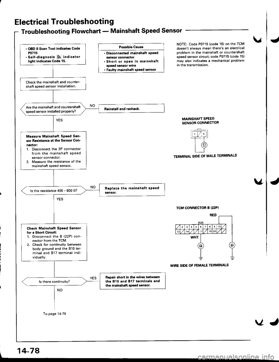
Troubleshooting Flowchart - Mainshaft Speed Sensor
Po3aiblo causo
' Diaconnocted mrin3haft spocd30nsor connoctot. Short or open in mainshsttsoeod senSot wito. Faulty main3halt spood 3€n3ol
vNOTE: Code P0715 (code '15) on the TCM
doesn't always mean there's an electrical
oroblem in the mainshaft or countershaftspeed sensor circuit; code P0715 (code l5)
may also indicates a mechanical problem
in the lransmission.
MAINSHAFT SPEEDSENSOR CONNECTOR
TERMINAL SIDE OF MALE TERMINALS
TCM CONNECTOR B (22P)
WIRE SIDE OF FEMALE TERMINALS
\4
' OBD ll Sc.n Tool indicrt6 Codo
P0715' self-diagnosis El indicalorlight indicatos Code 15.
Check the mainshatt and counler-shaft soeed sensor installation.
Are the mainshaft and countershaltspeed sensor installed properly?
M6asure Mainshtft Spood Son'
sor Rgsi5tanco at ths Sonsol Con-
nec'tor:'t. Disconnect the 3P connectorIrom th6 mainshatt speedsensor connedor,2. Measure the rcsistance of themainshaft speed sensor.
ls the resistance 400 - 600 o?
Chock Mainshaft Speed Son3orfor a Short Circuh:l. Disconnect the B (22P) con-nector lrom the TCM.2. Check lor continuity betlveenbody ground and the 810 ter'
minal and 817 terminal indi-
vidually.
Repair 3hort in tha wi?es bttwo€ntho 810 lnd Bt? terminal3.ndtha mainshltt spaed sonaot.
To page 14-79
, 14-74
VJ
Page 498 of 1681
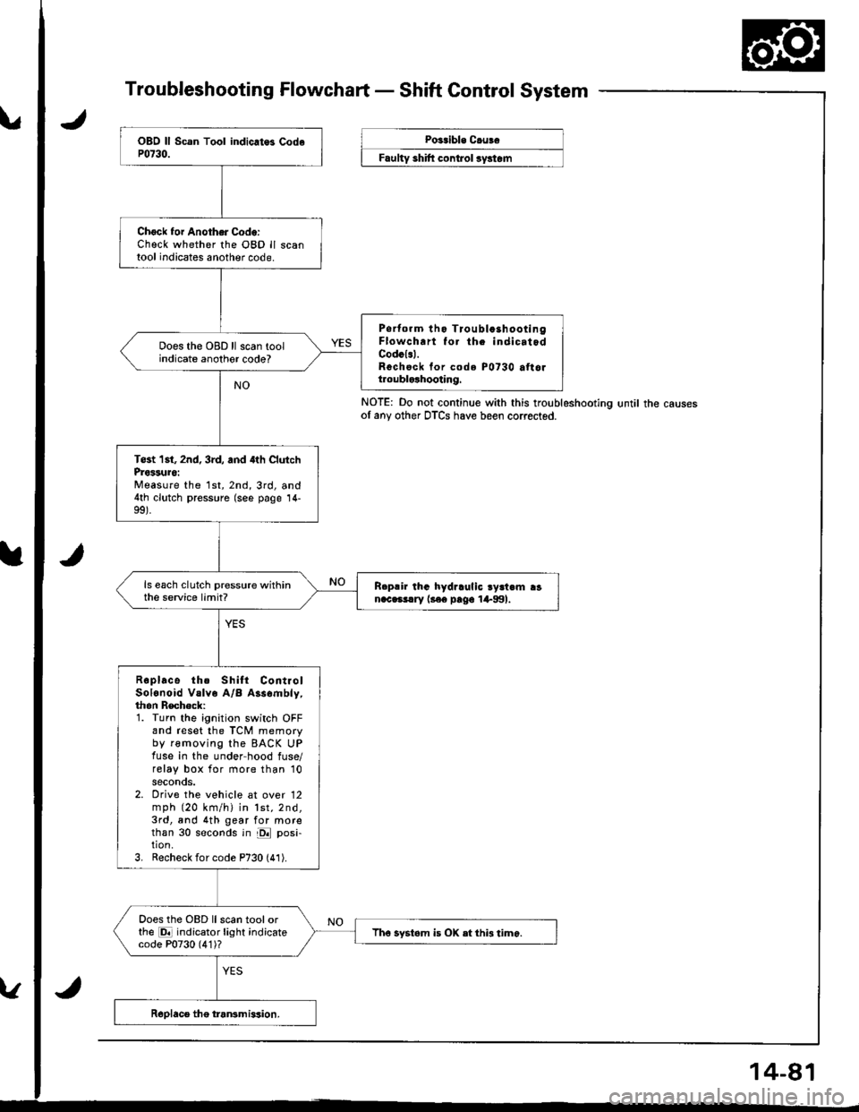
Troubleshooting Flowchart - Shaft Control System
NOTE: Do not continue with this troubleshootlng until the causesof any other DTCS have been corrected.
Chock foi Another Code:Check whether the OBD ll scantool indicates another code.
Psrtorm tho Tioubla3hootingFlowch.rt fo. th. indicatodCodcl.l.Rechsck tor code P0730 attoltroublolhooting.
Does the OBD ll scan toolindicate anothor code?
Tost 1st, 2nd, 3rd, and 4th ClutchProssuro:Measure the 1st,2nd,3rd, and4th clutch pressure (see page 14-
ls each clutch pressure withinthe service limit?R.p!ir lhG hydraulic ry3t.m ranac.3!.ry l3€e pago 1+991.
Roplace the Shilt ContiolSolonoid Valve A/B Assombly,thon Recheck:1. Turn the ignition switch OFFand reset the TCM memoryby removing the BACK UPfuse in the under-hood fuse/relay box for more than '10
seconds.2. Orive the vehicle at over 12mph (20 km/h) in lst,2nd,3rd, and 4th gear for morethan 30 seconds in E posi-tion.3, Recheck for code P730 (41).
Does the OBD llscan toolorthe E indicator light indicatecode P0730 (4'1)?Tho systom is OX etthi3 timo.
Poitible C.uBe
F""lty "hlft ".^t..t ",/"t".
Page 499 of 1681
Electrical Troubleshooting
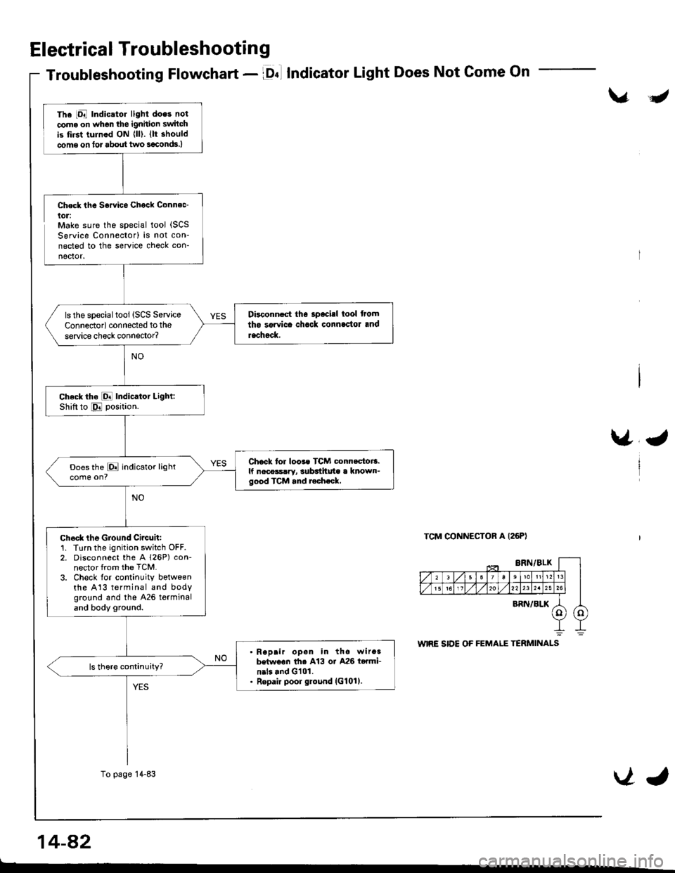
Troubleshooting Flowchart - lDnl IndicatorLight Does Not Come On
\/J
Check the Sowice Chock Connec-lol:Make sure the special tool {SCSSorvice Connector) is not con-nected to the service check con-
nector.
\/J
TCM CONNECTOR A I26PI
The iDal Indic.tor light does not
coma on whgn the ignhion switchis tirst tulnod ON {ll). (lt should
come on tor about two s€conds.)
Disconnect the 3pocisl tool from
tho sgrvice chock connlc'tor and
rachock.
ls the specialtool (SCS Service
Connedor) connected to the
service check connector?
Ch.ck tho [O! Indicator Light:Shiftto E position.
Chock tor loos. TCM conn.ctoi3.lf nece3s!ry, subttitute a known-good TCM and r.ch.ck,
Does the E indicator lightcome on?
Ch.ck the Ground Circuit:1. Turn the ignition switch OFF.2. Disconnect the A 126P) con-nector from the TCM.
3. Check lor continuity botweenthe A13 terminal and bodyground and tho 426 terminaland body ground.
Reprir opan in the wir.3betwoon th6 A13 or A26 t..mi-nil. and G101.Repair poor ground (G101).
To page 14-83VJ
14-a2
t-
Page 500 of 1681
\.
\.
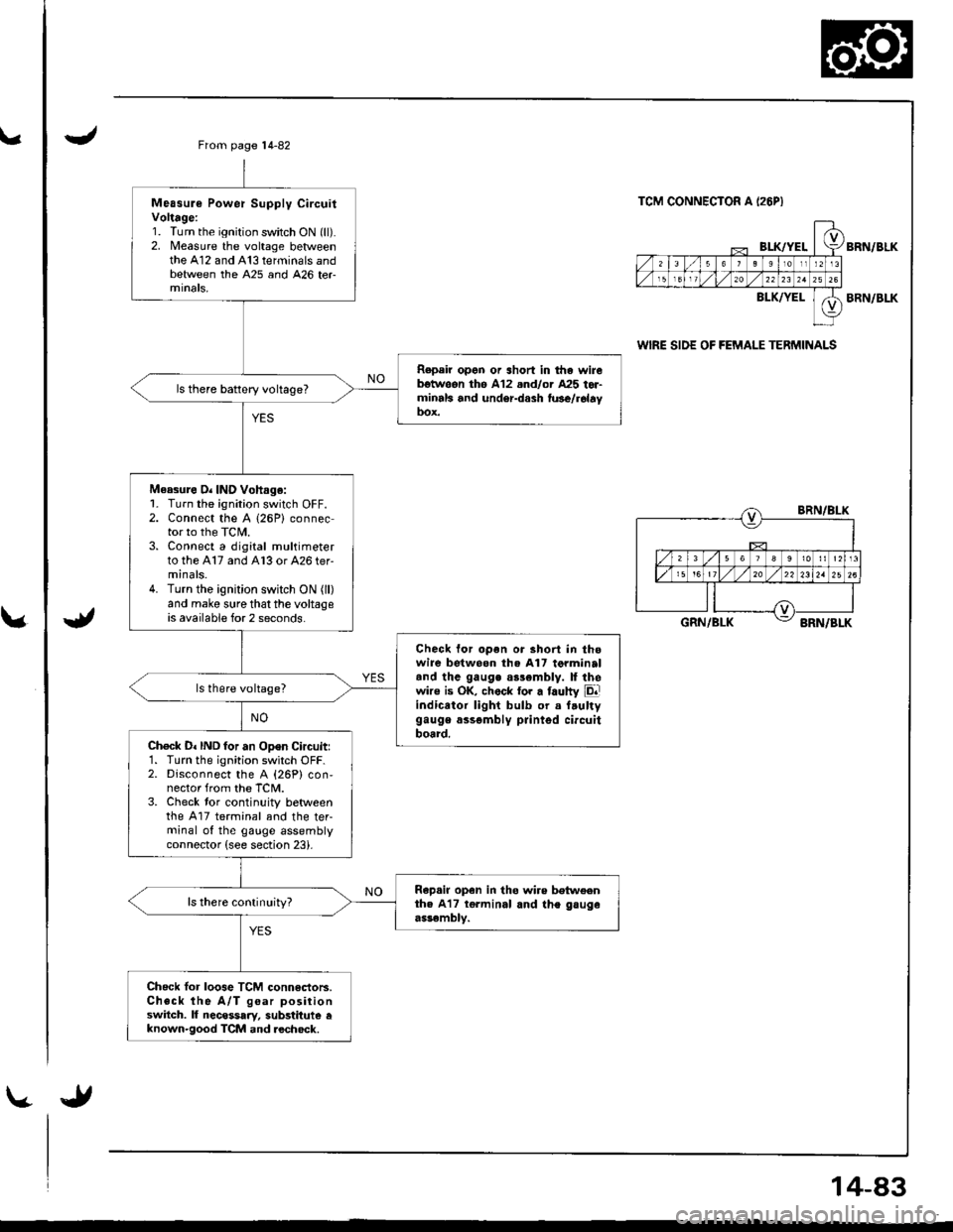
Measure Power Supply CircuitVoltage:1. Turn the ignition switch ON (ll).2. Measure the voltage betweenthe A12 and A13 terminals andbetween the A25 and 426 ter
Repeir open or short in tha wirebgtwoon th6 A12 .nd/or A25 tor-minrls and under-dash fu3e/r6layDox.
ls there battery voltage?
Measure O. IND Vohag.:1- Turn the ignition switch OFF.2. Connect the A (26P) connector to the TCIL3. Connect a digital multimeterto the A17 and A13 or 426 ter-minals.4. Turn the ignition switch ON (ll)
and make sure that the voltageis available for 2 seconds.
Check for open or short in thowire betweon the A17 torminaltnd the gauge as3emblv. ll thewire is OK, chock tor a faulty Eliindicator light bulb or a f.ultygauge assgmbly printgd circuitboard.Ch€ck D. IND for an Open Circuitr1. Turn the ignition switch OFF.2. Disconnect the A {26P} con,nector from the TCM.3. Check tor continuity betweenthe A17 terminal and the teFminal of the gauge assemblyconnector (see section 23).
Rap.ir open in tho wire betweenth. A17 tgrminal and the gsugeassembly.
ls there conlinuity?
Check lor loose TCM connectoB.Check the A/T goar positionswitch. lf necessary, substitute eknown-good TCM and.echock.
From page 14-82
TCM CONNECTOR A I26PI
BI-K/YELBRN/BLK
BLK/YELBRN/BLK
wlRE SIDE OF FEMALE TERMINALS
BRN/BLK
GRN/BLKBRN/BLK
14-83
Page 501 of 1681
Electrical Troubleshooting
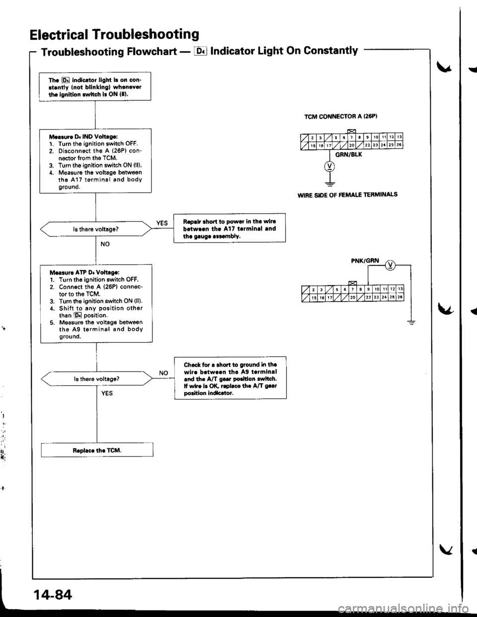
Troubleshooting Flowchart - EIndicator Light On Gonstantly
v
ICM CONNECTOR A I26PI
\4
I
i
rlIti
Th. E indicltor ligM i! on cor.
.t.ntly Inoi blinllng) wh.n.Y.l
th. lgrhior lwftch l. ON {ll).
M...ur. D. INO Vohtg.:1. Turn tho ignition switch OFF.
2. Disconnect th€ A (26P) con-noctor from the TCM.3. Turn the ignition switch ON (ll).
4. Measure thg voltag€ bstwegnthe A17 t6rminal and bodyground.
Rapalr ahort to powar In tha wiru
b.tw..n th. A17 l.rmin.l lnd
tha gaug. .cr.mbly.
M.a3ur. ATP D. voh.g.:1. Turn the ignition switch OFF.2. Conn€ct th€ A (26P) conn€c-tor to the TCM.3. Turn th€ ignition switch ON (ll).
4, Shift to any position otherthan E position.
5. Moasure the vohag€ b€tweenthe A9 tormin.l and bodyground.
Ch.ck tor r rhort to ground in thawir. b!tw..n th. Ag tarmin.l.nd th. A/T g..r potfion lwltch.f wi.e b OK r.pllca th. A/T g.|rpolition Indacrtor.
WIRE SIDE OF FEMAI.I TERMINALS
!
{
Page 503 of 1681
Electrica I Troubleshooti n g
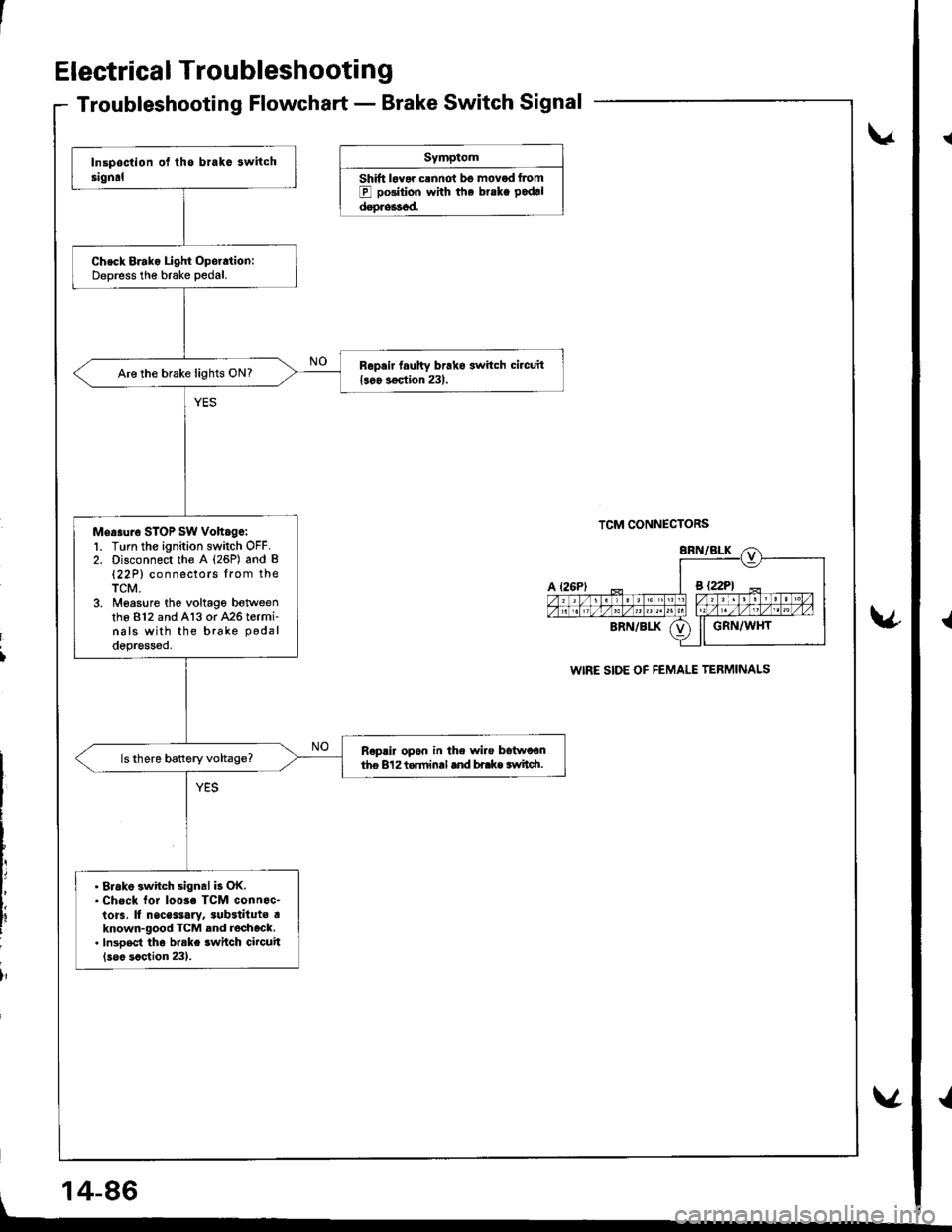
Troubleshooting Flowchart - Brake Switch Signal
Symptom
Shift lovar clnnot bo moved Itom
E pGition with the brske pod.l
dsoressod.
v
TCM CONNECTORS
WIRE SIDE OF FEMALE TERMINALS
v
i
lr
Check Brako Light Oporation:Deoress the brake Dedal.
Repair taulty brako switch circuit{soo 3€qtion 231.Are the brake lights ON?
Mea.ur6 STOP sw voh.ge:1. Turn the ignition switch OFF.2. Disconnect the A (26P) and B(22P) connectors lrom theTCM.3. Moasure the voltage botweenthe 812 and A13 or 426 termi-nals with the brake podal
depressed.
R€plir opon in the wire Itstwoonth€ 8'l2 torminal and bi.ke svtidt.
. 8rak6 switch signal b OK.. check lor loose TcM connoc-to]s, lf nsce$ary, sub3tituts aknown-good TcM and rochock.. lnsooct tho brake swilch circuit(soo scction 231.
, 14-86
v
{
{
Page 507 of 1681
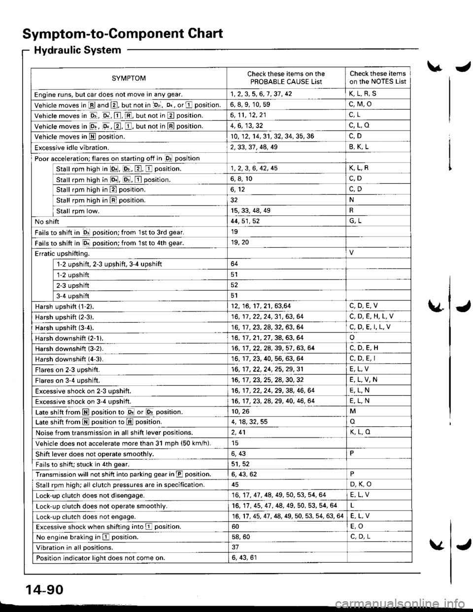
Symptom-to-Component Chart
Hydraulic System
SYMPTOMCheck these items on the
PROBABLE CAUSE List
Check these items
on the NoTES List
Engine runs, but car does not move in any gear.1,2,3,5,6,7,37, 42K,L.R,S
Vehicle moves in E and E, but not in lD,l, D. , or E position.6, 8, 9, 10, 59c,M,o
Vehicle moves in E, o.-, E, E, but not in E position.6,11,12,21c.L
Vehicle moves in 9r, 9. , E, E, but not in E position.4,6, 13,32c,L,o
Vehicle moves in E position.10, 12, 14, 31, 32, 34, 35, 36
Excessive idle vibration.2,33, 31, 44, 49B,K,L
Poor acceleration; flares on starting off in D! position
Stall rpm high in lQ|. E, E, E position.1, 2, 3, 6, 42, 45K,L,R
stall rpm high in lo.tl. ld, E position.6, 8, 10c.D
Stall rpm high in E position.
Stall rpm high in B position.32N
tat"tkp,ril"*'15,33,48,49R
No shift44, 51, 52G,L
Fails to shift in ql position; from 1st to 3rd gear.19
Fails to shift in E position; from lst to 4th gear.19, 20
Erratic upshifting.
1-2 upshift, 2-3 upshift,3-4 upshift64
fiz upshift
ETupshift52
Ia-+ upstrifi5l
Harsh upshift {1-2).12, 16, 11,21,63,64C,D,E,V
Harsh upshift (2-3).16,17,22,24,31,63,64C,D,E.H,L,V
Harsh upshift (3-4).16,'�tl. 23, 28, 32, 63, 64C, D, E. I,L.V
Harsh downshift (2-1).16, 17,21,27,34,63,64o
Harsh downshift (3-2).16, 11 ,22,2A,39,57 ,63, 64
Harsh downshift (4'3).16, 17, 23. 40, 56, 63. 64C, D, E, I
Flares on 2-3 upshift.16, 17 ,22,24, 25,29,31E,L,V
Flares on 3-4 upshift,16, 11 ,23,25,24,30,32E,L,V,N
Excessive shock on 2-3 uDshift.16, 11, 22, 24, 29, 38, 46, 64E,L.N
Excessive shock on 3-4 upshift.16, 11 , 23, 2a,29, 40, 46, 64E,L,N
Late shift from E position to d or E position.10, 26M
Late shift from M position to L!!l position.4, 18,32,55o
Noise from transmission in all shift lever Dositions.2,41K,L,O
Vehicle does not accelerate more than 31 mDh (50 km/h).
Shift lever does not operate smoothly.6, 43P
Fails to shifu stuck in 4th gear.5'1,52
Transmission will not shift into parking gear in JII position.6, 43, 62P
Stall rpm high; all clutch pressures are in specification.D,K,O
Lock-up clutch does not disengage.16,17, 47, 48,49, 50, 53, 54, 64E,L,V
Lock-up clutch does not operate smoothly.16, 17, 45, 47 , 48, 49,50, 53. 54, 64
Lock-up clutch does not engage.16,17, 45, 47, 48, 49,50, 53, 54, 63, 64E,L,V
Excessive shock when shifting into E position.60
No engine braking in E position.58, 50C,D.L
Vibration in all positions.
Position indicator light does not come on.6, 43, 61
\.J
\4J
v
14-90
L------�
J
Page 538 of 1681
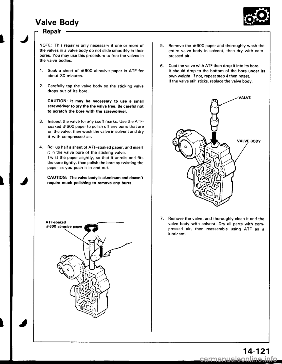
NOTE: This repair is only necessary if one or more of
the valves in a valve body do not slide smoothly in their
bores. You may use this procedure to free the valves in
the valve bodies.
1. Soak a sheet of # 600 abrasive DaDer in ATF for
about 30 minutes.
2. Caretully tap the valve body so the sticking valve
drops out of its bore.
CAUTION: lt may be necessary to use a small
scrawdriv6r to pry the the valve f.66. Bs caloful not
to sciatch th€ bole with th6 scrowdriver.
Remove the #600 paper and tho.oughly wash the
entire valve body in solvent, th€n dry with com-
pressed air.
Coat the valve with ATF then droD it into its bore.
It should droD to the bottom of the bore under its
own weight. lf not, repeat step 4 then retest.
lf the valve still sticks, replace the valve body.
InsDect the valve for anv scuff marks. Use the ATF-
soaked # 600 paper to polish ofl any burrs that are
on the valve. then wash the valve in solvent and drV
it with compressed air,
Roll up halt a sheet ot ATF-soaked paper, and insert
it in the valve bore of the sticking valve.
Twist the paper slightly, so that it unrolls and fits
the bore tightly. then polish the bore by twisting thepaper as you push it in and out.
CAUTION: The valvs body is aluminum and doesn't
require much polishing ro lomovo any bulla.
VALVE BODY
7.Remove the valve. and thoroughly clean it and the
valve body with solvent. Dry all parts with com-pressed air, then reassemble using ATF as alubricant.
Valve Body
Repair
14-121
Page 634 of 1681
t
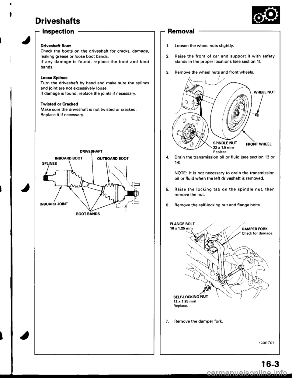
Driveshafts
Inspection
Drivcshatt Boot
Check the boots on the driveshaft tor cracks. damage,
leaking grease or loose boot bands.
lf any damage is found, replace the boot and boot
oanos.
Looso SplineE
Turn the driveshaft by hand and moke sure the splines
and joint are not excessively loose.
lf damage is found, replace the joints if necessary.
Twisled or Crscked
Make sure the driveshaft is not tlvisted or cracked.
Replace it if necessary.
BOOT BANDS
1.Loosen the wheel nuts slightly,
Raise the front of ca. and support it with safety
stands in the prope. locations {see section 1).
Remove the wheel nuts and front wheels.
5.
Drain the transmission oil or fluid (see section 13 or
14t.
NOTE: lt is not necessary to drain the transmission
oil or fluid when the left driveshaft is removed.
Raise the locking tab on the spindle nut, then
remove the nut.
6. Remove the self-locking nut and flange bolts.
FLANGE BOLT'10 x 1.25
SELF.LOCKING NUT
12 x 1.25 mmReplace.
(cont'd)
Replace.
7. Remove the damoer fork.
Removal
6-3
Page 658 of 1681
INPUT SHAFT
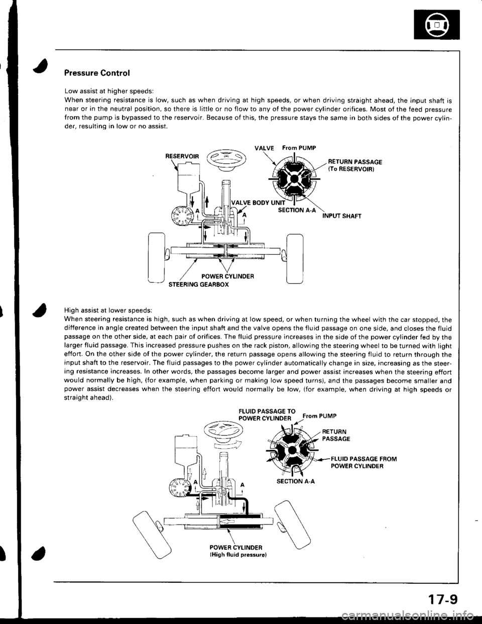
High assist at lower speedsl
When steering resistance is high, such as when driving at low speed, or when turning the wheel with the car stopped, the
diiference in angle created between the input shaft and the valve opens the tluid passage on one side, and closes the fluidpassage on the other side, at each pair of orifices. The fluid pressure lncreases in the side of the power cylinder fed by thelarger fluid passage. This increased pressure pushes on the rack piston, allowing the steering wheel to be turned with light
effon. On the other side of the power cylinder, the return passage opens allowing the steering fluid to return through theinput shaft to the reservoir. The fluid passages to the power cylinder automatically change in size, increasing as the steer-ing resistance increases. In other words, the passages become larger and power assist increases when the steering effort
would normally be high, (for example, when parking or making low speed turns), and the passages become smaller andpower assist decreases when the steering effort would normally be low, (for example, when driving at high speeds or
straight ahead).
FLUIO PASSAGE TOPOWER CYLINDER
Ce) r.r;
VK
Pressure Control
Low assist at higher speedsl
When steering resistance is low, such as when driving at high speeds, or when driving straight ahead. the lnput shaft is
near or in the neutral position, so there is liftle or no flow to any of the power cylinder orifices. Most of the feed pressure
from the pump is bypassed to the reservoir. Because of this, the pressure stays the same in both sides of the power cvlin-
der, resulting in low or no assist.
RETURN PASSAGE{To RESERVOIR)
POWER CYLINDERlHigh fluid pressurelI
ALVE FTom PUMP
RESERVOIR
SECTION A-A
17-9