relay HONDA INTEGRA 1998 4.G Workshop Manual
[x] Cancel search | Manufacturer: HONDA, Model Year: 1998, Model line: INTEGRA, Model: HONDA INTEGRA 1998 4.GPages: 1681, PDF Size: 54.22 MB
Page 1469 of 1681
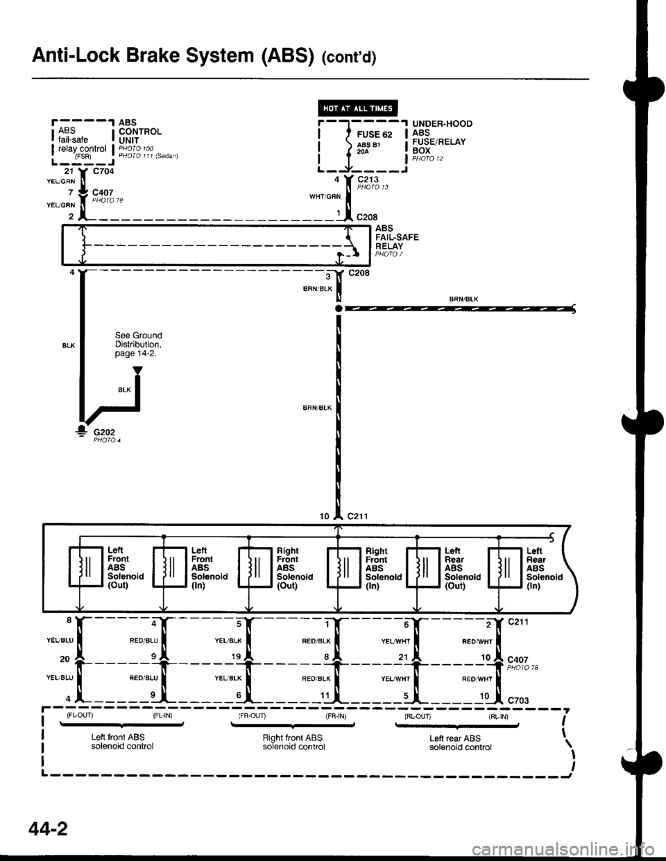
Anti-Lock Brake System (ABS) (cont'd)
r----'t
rA?.?"" I
I relayconkol IL-:-:-J21 Y C7O4YEL/GRN II
z iL coo,
ABSCONTROLUNIT
UNDER"HOODABSFUSE/RELAYBOX
-*i[::
ABSFAIL-SAFERELAY
:F
BRN/BLK
c21110
---il'cztt
"aotrn, I
_____:$ r**,,
___:il.[ ",..
;;r
11[
;."7
:][
ra'{
_:,.,!-
;_'r[
:tt
i-l-;;.-
l-l-:--o r F"%"3,"
::t.1",.,
L6ftFrontABSSolenoid(out)
RightFrontABSSolenoid(ouU
LeftFrontABSSolenoid(ln)
LefiSearABSSolenoid(out)
FL.OUI (FL,|N) (Fn-OUI {FntN) (BL-OUT) lBL,tN) ,-it- --8, r-q-d ,
Left tront ABS Riohl lront ABS t 6ft rerr ABs t-Left tront ABS Right front ABS Left rear ABSsolenoid control solenoid control solenoid conlrol \
I
44-2
Page 1470 of 1681
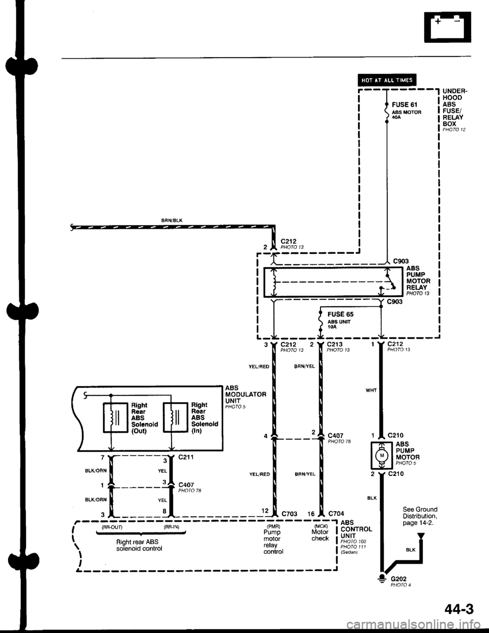
UNDEB.HOOOABSFUSE/RELAYBOX
FUSE 61AAS MOTOB
IJ13,x?i;,z-r
ABSPUMPMOTORRELAYPHOTO 13
FUSE 65aas uMr!0A
See GroundDiskibution,page 14-2.ABSCONTROLUNIT
------'.-=-l
, r'F.oun y (BB.r\, ,,,!$R #?$ t
I o'^*r.^.. ooc motor check I: Rioh rear ABS ioT"rioiJ-ntror reraV ,I *--" *' '- conkol
t
4
aightnearABSSoleroid(ln)
RighlnearABSSolenold(out)
::[----,il;
PUMPMOTOB
G202
44-3
Page 1473 of 1681
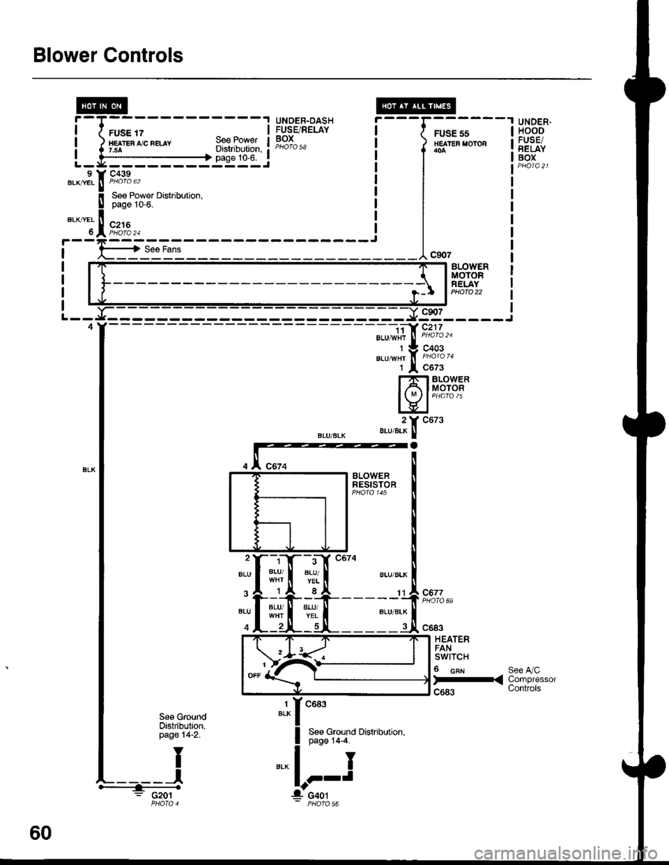
Blower Controls
FUSE 17HE TEn ,'/C nELAY7.5ASee PowetDistribution,page 10-6.
UNDER.DASHFUSE/RELAYBOX
---G;;-'
/ HEATER I'OTOR
l*^
I
I
I
---1"*'
UNOER.HOODFUSE/RELAYBOXL - y' - - - - - - - -:: - - J9 Y C439.KryEL ! P/roro 62BLK|/EL ll PHOIO 62
BLOVYERMOTORFELAYPHOTO 22
9s_____i
".u-", f, i'ii'o '.
1 l c6z3
Hfib#i
".,,".?[ "ut'
- -i;a' c217BLU 1,vi{r
J
PHoro '�u
C677PHOTO 69:rI#
c683
HEATERFANswtTcH
6 cnr
)-<
See A/CCompressorControls
1BLKc683
See Ground Distribution,page 14-4.
I
J
See GroundOistribution,page 14-2.
: G201
60
Page 1477 of 1681
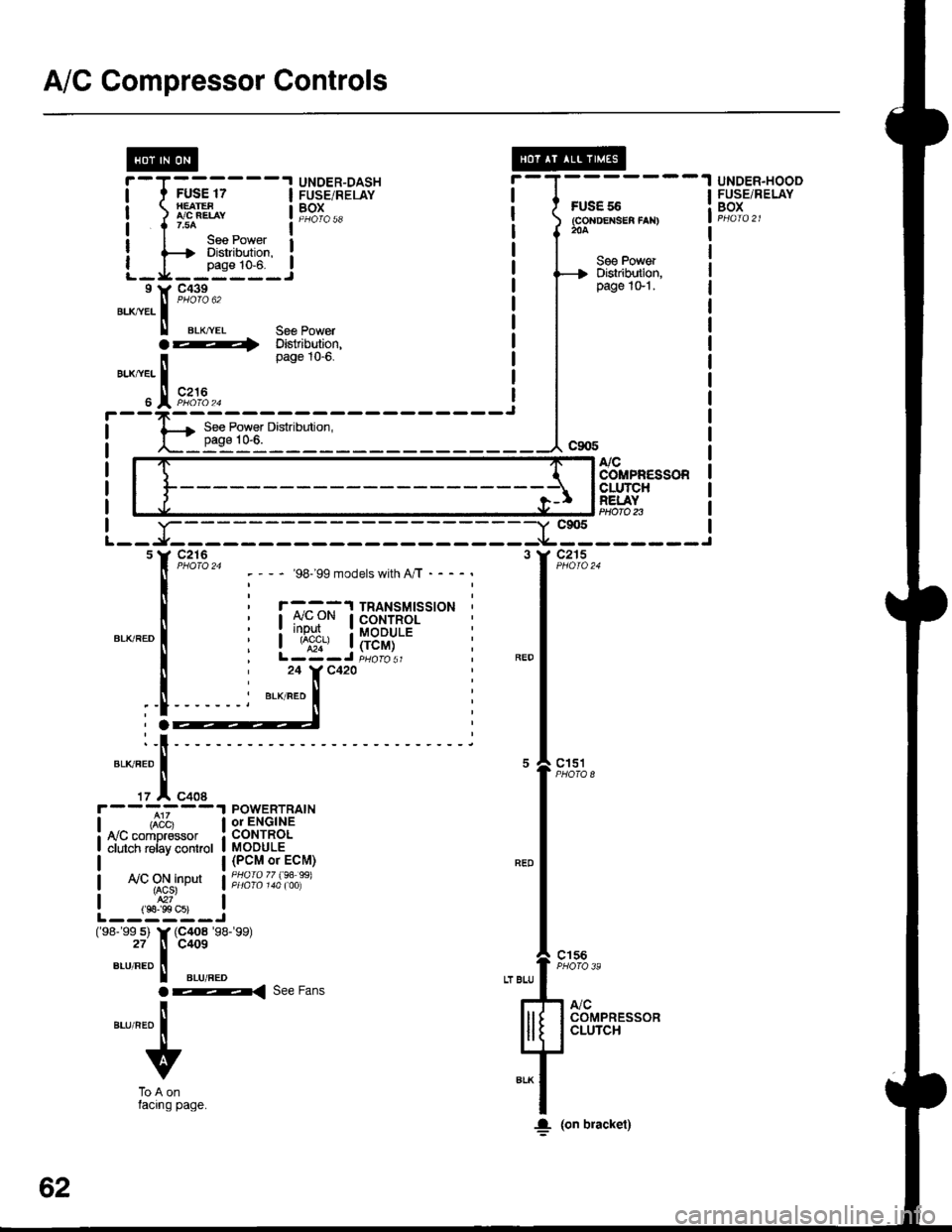
A/C Gompressor Controls
FUS€ 55(GoNDEXSEA fAN)204
UNDER.HOOOFUSE/RELAYBOX
@r-T------.I UNDER-DASHI t FUSE 17 I FUSE/RELAY
| ) LBEL, t19T^..
I I r.uo ^ _ l--*I I lee Power I: {--t Diskibdion. :
L_I_fiT_.!I Y C439
".^,tr. |
"'oto u'
ll erx,.ver 36€ Powera ---i Distribution,page tO-0.
BLX/YEL I
" IFi:,u.^
See PowerDislribution,page 1G'l .
NCCOMPR€SSORCLUTCHREI.AYPtloro n-Y c905
-*----------f
"*l'--
,1,*,
"-l
"ft:,,
lll[ 133,]+'"1F**
;f
I. (on bracket)
- '98199 models with A/T - - - -
r -^ ^-^:'l TRANSMTSSTONCONTROL: rr!P!I.. : MoDULE| ^;;', | (rcM)L-Z-J iuoro sr24 Y C420
BLK/RED
POWERTRAINor ENGINECONTROLMODULE(PCM or ECM)PHOfO 77 (94 99)ly'C ON inDut{ACS}
L--,S"s-i(98- 99 s) Y (C4o8 '�98-'�99)
27 tl C409
",-r,"ao II aLuneo
ar< ree Fans
ilaurneo I
v
ToAonlacrng page.
62
Page 1478 of 1681
From A onlacrng page.
v^,..^-^ i"'""14
"";+,eru,neo I
z A ctuo
FUSE 17llEAtES ,i/C iELAYt.lta
UNDER-OASHFUSE/RELAYBOXPHO|O 58Sg€ PowarDistributlon,
A/C PRESSUREswrTcHLow: Open below 200 kPa (28 psi).High: Open above 3100 kPa (460 Psi).
Dislributlon,page 10€."a*,tra ll
".,. ifrF'fl%"
A,/CTHERMOSTATOtf below3'C (37"F).
THERMISTOR
See AirDelivery
BLKTYEL Se€ PoweT
4 il"Stt",j'::'
,i/c oNIt{DICATOR
A,/CswrcH
I CoNTROL
iPANEL
rO
:tI
a
il
au,vel N
t
__':rc684
1YC1s4"rr*1r ! ^...
".,r*", I i'abi6 o
ro J cco+;r't::
2 Y C676BLU]REO II
".",1.t"fr 9,9%,,
rrl--.
62-1
Page 1479 of 1681
A/C Gompressor Controls (conrd)
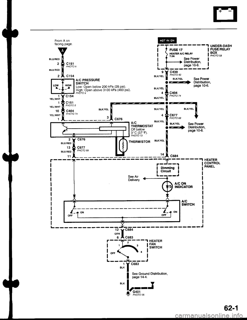
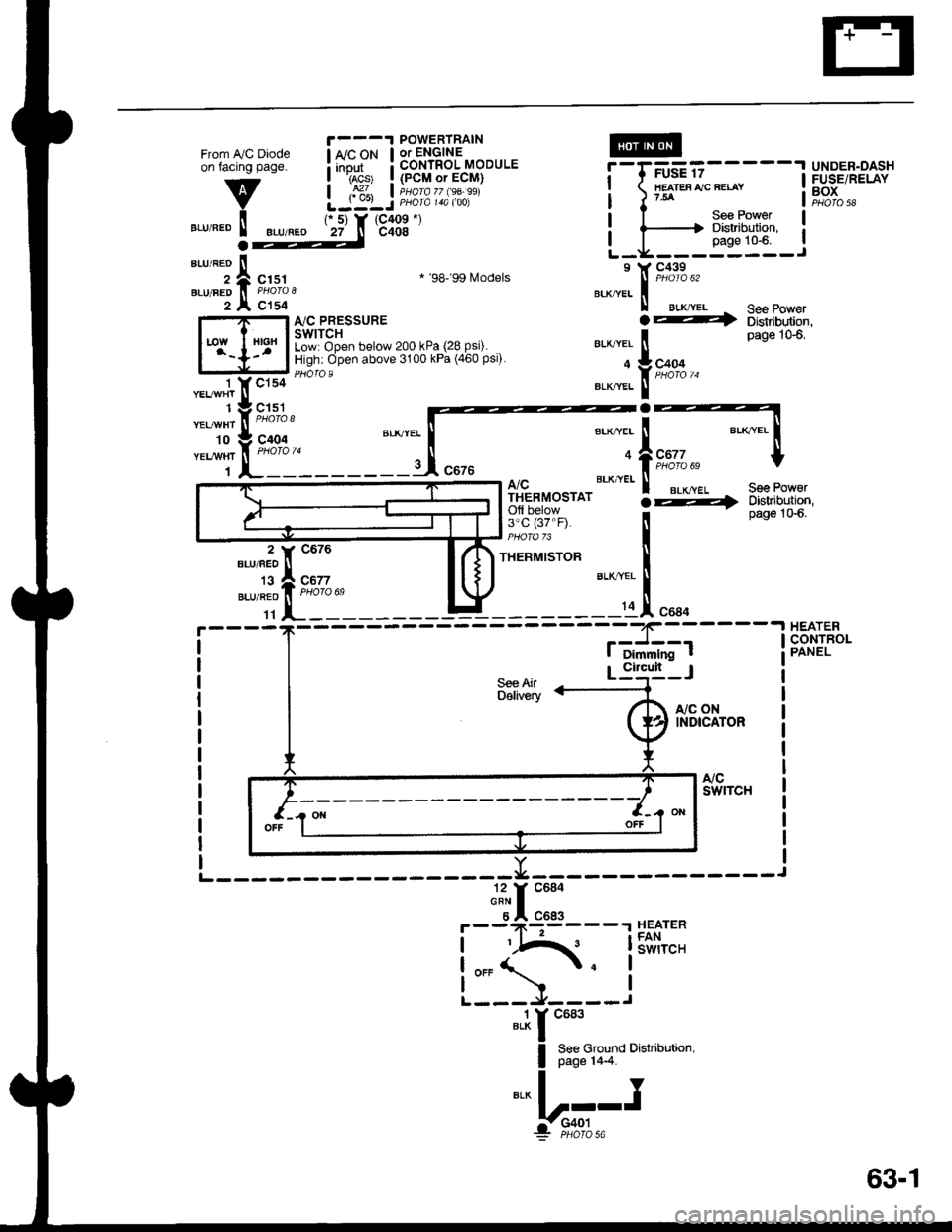
- How the Circuit Works
Battery voltage is supplied through fuse 56 to the
A,/C compressor clutch relay contacts at all times.
With the ignition switch in ON (ll), voltage is applied
to the coil of the A,/C compressor clutch relay
through fuse 17. When you push the A,/C switch
ON, and the heater fan switch is in posation 1, 2, 3,
or 4, a "ground" input is provided to the engine or
powertrain control module (ECM or PCM) through
the A,/C thermostat and the A,/C pressure switch.
The A,/C compressor clutch relay is grounded by the
engine or powertrain control module (ECM or PCM).
When energized, the A,/C compressor clutch relay
allows battery voltage to turn on the A,/C
comDressor clutch,
The A,/C ON indicator light comes on when the A"/C
system is requested.
A,/C Thermostat
The A,/C thermostat is located on the evaoorator
housing. The AJC thermostat turns off the A,/C
compressor clutch if the temperature at the
evaporator goes below 3'C (37'F). This prevents
condensation from freezing on the evaporator fins
and blocking the air delivery into the passenger
compartment. The blower motor will keep running
when the sensor lurns off the compressor.
A,/C Pressure Switch
The A,/C pressure switch is located in the condenser
outlet line where refrigerant is in a high
temperature/high pressure liquid state. The switch
will sense abnormally high or low pressure, and
open the circuit. This removes ground, and the
compressor will stop running.
Refer to the Service Manual (Section 22,
Air Conditioning) for specific tests or
troubleshooting procedures.
62-2
Page 1480 of 1681
Fans
- with
|------
See PowerDistribution,page 1G6.
;;;----13X3,5"
l,fP"[r s"" eo'""t
A/C -
E@
UNDER.HOODFUSE/RELAYBOXDistribution,
FUSE 56(coxoEr{sE8 faN}FUSE 57COOLING
204
FUSE/RELAY
2
(Not
I
I
I
I
IL
I Y C439sucrel ll PHoro"62rrr.
orl
*T'.I.
:-gg]gi Ji,'oio,,,
Seg PowerDistribution,page 10.6.c216y":':---______i
See PowerDbtribution,page lG1.
c2'16 1
BLKBEO
' POWERTRAIN ,
: or ENGINE, CONTROL ::,::A ,. ' MODULE ;(PCM or ECM) ,' PHOIA 77 (9A 99 |' PHofa 14a $q :!---- usA.----
COI{DENSERFANRELAYPHOTO 23
RADIATORFANRELAYHlofa 22
c215-----J
* '98199 [,4odels
cltl8LU/BLK
c9{t6
c206
c206
ffi-
".",".t"f
"oo' 6
i
v
To Splice onfacing page
c151
c155
BLU/BIK
BLU/ALK
CONDENSERFANMOTOR
RADIATORFANMOTOR
RADIATORFAN SWITCHClosed above93"C (200"F).
".:r
"'''
I see c,ornoarr< Distribution,
".,.f
','"i.
-lr:;--: PHafo 28
c155PHOTA 9
See GroundDistribution,page 14-2
Y
I
63
I. G151
Page 1481 of 1681
From IVC Diodeon facing page.
v
".r,".o ! ".u,".o
1 YCls4 '- --
"t"*1t ,I, ^..,
-t'I:::'
ri'fft_____:_
POWERTRAIN
! *'"P* ! 3b'nli?3'-"oou'.I rAcs' I {PCM or ECM}
| ,S1, I iuorozz $a.ssiLJ:LJ PHora 14a too)IIEATES IJC RELAY?54
UNDER.DASHFUSE/RELAYBOXPHO|O 58
r 5) Y (C409 *)
27 n c408
See PowerDistribution,page 10-6.a
";;;ic151
c154
* '98'�99 Models
I'lC PRESSURESWITCHLow: Open below 200 kPa (28 Psi).High: Open above 3100 kPa (460 Psi).
.4
See Po' erDistribution,page 106,
See PoworDbtribution,page 1G6.
A/CTHERMOSTATOfl below3'c (37"F).
THERMISTOR
S€e AirDelivery
"a*a, i
*,*rfrs,*lt-
a
BTK,"VEI i
9:1L"" t
::;1".,.
I Dimmlng t
-.I HEATER,J--- I cONrR(CONTROL
Circult
r,/c oNINDICATOR
".1r "ur'
I 8:8ffiTo
o'"u''"''n'
*!r".-
F--9*l:93----r HEATER
!iIA{. lSiii,"'.
L:5-l--i
63-1
Page 1482 of 1681
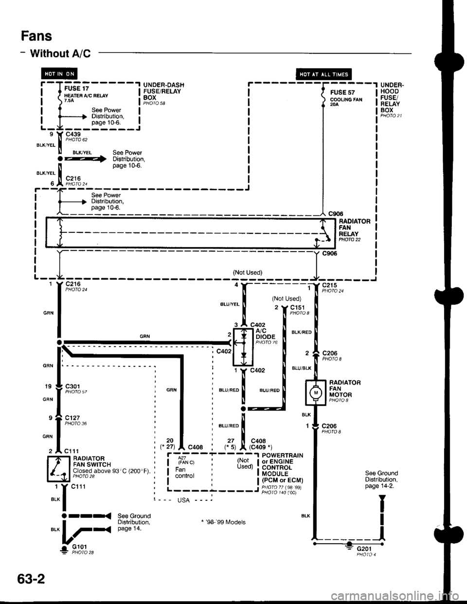
Fans
- Without A/C
UNDER-HOODFUSE/RELAYBOX
r--------UNDER-DASHFUSE/RELAYBOXFUSE 57cooLrfic FAx2oa
a4 Distribution,
_ ' Cg(F
ll Pase 106'BLK,YEL I
. A """?t'3"---------JI Soe Powgri------{' Distribution,
I page 10-6./\-_--_--
'I
GBN
RADIATORFANRELAYP|1OTO 22
: l__
ru::
.i
-d*"^
ffil u
(Not Used)---?f;---------==:
I (Nor Used)BLUT'EL
f
"
f,r;.;
.l "oo, I
'[TliiF:,- il
"'*,'
-r-I I "-'" I
i*'Er t: 11,c402 i
*-
:lI' Btu'RED I er-uraeo I
i 3__J
:ilt; ".r,".o I
i ,, I "oo.: (. s) x (c4oe -)
l---rNTl:,oll,ffIE '"
: Used) I CoNTROL' I MODULE
: | (PcM or EcM). I PHA|O 77 (98 99):_----- PHOTO 140 taAl.,
)8 '99 Models
(Not Used)
?i-------=
,.'! rN(
. I .oo,PF.IA/c
Lf l"r,i"r,B%
ItlI .t. l
.:x
*::_,"."
24
t_
l'*
c301
PHOTO36
t9
GBN
See GroundDistribution,page 14-2.
I
I
_l
, r27) A C408
i r-;--, I iiiir o
; I FAN. I control;t, L----
I'irl RAOIATORI t I FANswtrcH
l{-cl 9J3?39,"-"e e3 c (2oo F)
1 Y c11r
"*l
Orr< See GroundI Distribution,BLK
L/-4
eaee 14.
1FJ�::.,"
usA ---.
* '98
._____.-'.1!;;6i-
PHO|O 4
63-2
Page 1483 of 1681
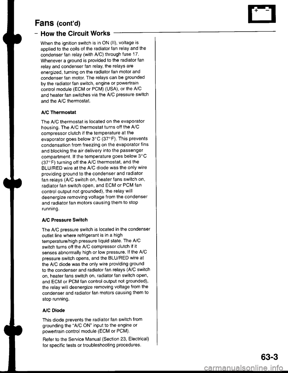
Fans (cont'd)
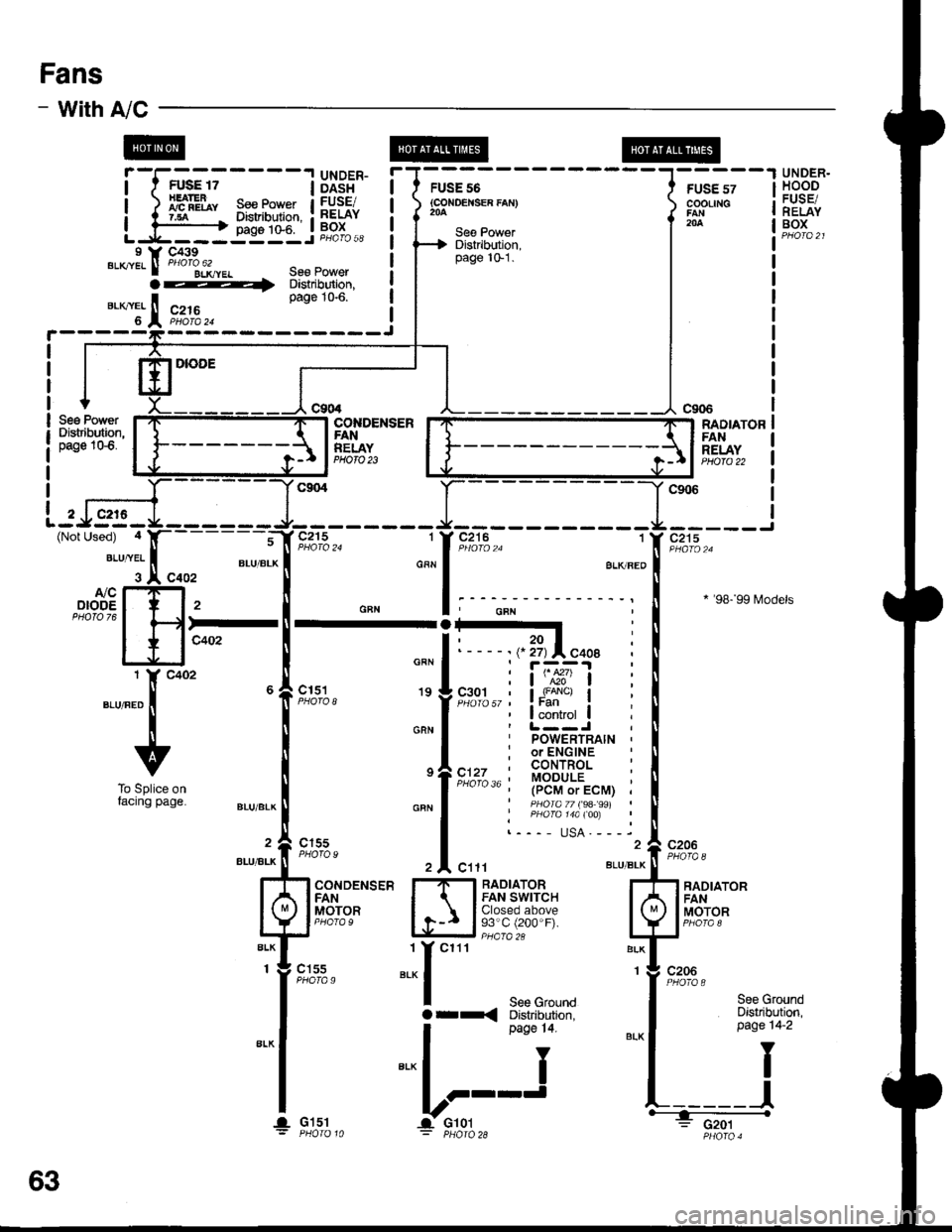
- How the Gircuit Works
When the ignition switch is in ON (ll), voltage is
applied to the coils of the radiator fan relay and the
condenser fan relay (with A,/C) through fuse 17.
Whenever a ground is provided to the radiator fan
relay and condenser fan relay, the relays are
energized, turning on the radiator fan motor and
condenser fan motor. The relays can be grounded
by the radiator fan switch, engine or powertrain
control module (ECM or PCM) (USA), or the A,/C
and heater lan switches via the A'lC pressure switch
and the A,/C lhermostat.
A,/C Thermostat
The A,/C thermostat is located on the evaporator
housing. The A/C thermostat turns oft the A/C
compressor clutch it the temperature at the
evaporator goes below 3'C (37"F). This prevents
condensalion from freezing on the evaporator fins
and blocking the air delivery into the passenger
compartment. lt the temperature goes below 3'C
(37'F) turning off the A"/C thermostat, and the
BLU/RED wire at the A,/C diode was the only wire
providing ground to the condenser and radiator
fan relays (A,/C switch on, heater fans switch on,
radiator fan switch open, and ECM or PCM fan
controi output not grounded), the relay will
deenergize removing voltage from the condenser
and radiator fan motors causing them to stop
running.
A,/C Pressure Switch
The AJC oressure switch is located in the condenser
outlet line where refrigerant is in a high
temperature/high pressure liquid state. The A,/C
switch turns off the A,/C compressor clutch if it
senses abnormally high or low pressure. lf the A'lC
pressure switch opens, and the BLU/RED wire at
the A/C diode was the only wire providing ground
to the condenser and radiator fan relays (L/C switch
on, heater fans switch on, radiator lan switch open'
and ECM or PCM fan control output not grounded),
the relay will deenergize removing voltage from the
condenser and radiator fan motors causing them to
stop running.
A./C Diode
This diode orevents the radiator fan switch f rom
grounding the "A'lC ON" input to the engine or
powertrain control module (ECM or PCM).
Refer to the Service Manual (Section 23, Electrical)
for specific tests or troubleshooting procedures.
63-3