fuse HONDA INTEGRA 1998 4.G Workshop Manual
[x] Cancel search | Manufacturer: HONDA, Model Year: 1998, Model line: INTEGRA, Model: HONDA INTEGRA 1998 4.GPages: 1681, PDF Size: 54.22 MB
Page 1557 of 1681
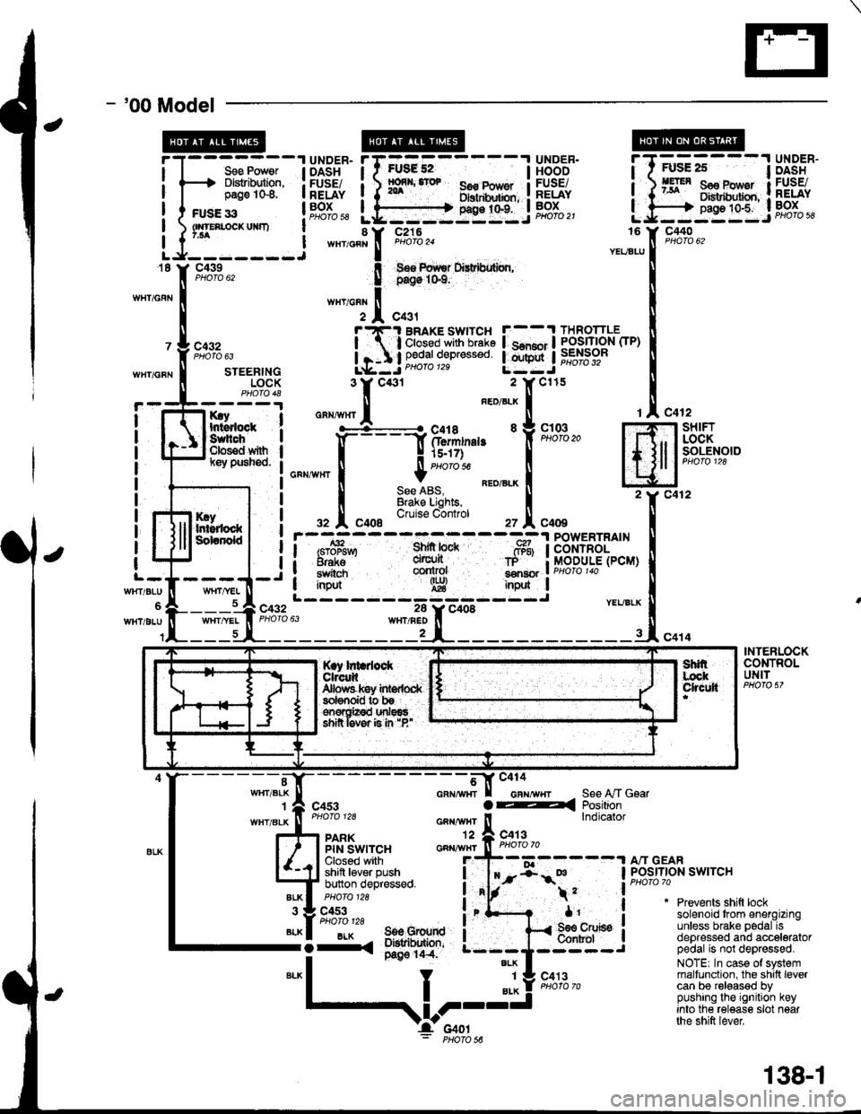
- '00 Model
I
I
FUsg 52I56€ Pow€r Ilxrtdhxbn, :g9:t"t:.i
UNDER.HOODFUSEiRELAYBOXPHOfO 21
Sse Power I DASHDlslribution, : FUSE/page 1G8. I RELAY
c440
c432
WHT/GFNSTEERINGLOCK
rry Ihtsdock :Suhch IClos€d with Il(ey pusned. I
I
I
I
I
I
I
c432
It
I
I
l-
WrtT/BLU
WHT/BLU
KryIr$rdockSdanold
c412-l SHIFT
, I LOCKI I SOLENOIDI lcuoto tzo
Jc412
c414
rAc4
m2Y c4
INtl
.-, I
i/BLX U
-rl"o
POWERTRAINCONTROLMODULE(PCM)
YEVBLX
INTERLOCKCONTROLUNIT
"-*;.'l[-
- - - - - - - -;*f-tr "'"'"'"-,,
r I casr a4
""""#"J;:.
_^ ll"ij*sa*,"
l4J $l't'"ii,''F:^,
*"T't. 3il1;'
;fi;ifJ,t""**o
i"'f- .
*1'
S€e A,/T GsarPositionlndicator
"liiffo,,' a"-BLK I 506 Grourd I-i-. ;*'o' ---;
*"1
I "l! s'*l'"-
Prevents shift locksolenoid trom energizingunless brake pedal isdepressed and acceleratorpedal is not depressed.
NOTE| In case of systemmalfunction, the shilt levercan be released bypushing the ignition keyinto the release slot nearthe shift lever
$l;---l UiSi'"
BRAKE SWITCH F--.t THROTTLE
;'3i:g*s::: !.mnj iffibr-
*,
,V-I'c4ol: PHoro s6
138-1
Page 1558 of 1681
lnterlock System
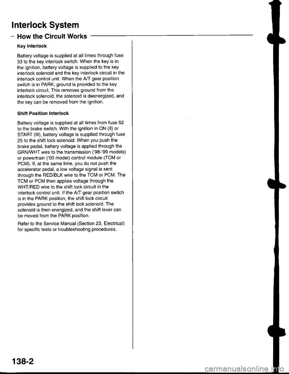
- How the Circuit Works
Key Interlock
Battery voltage is supplied at all times through f use
33 to the key interlock switch. When the key is in
the ignition, battery voltage is supplied to the key
intedock solenoid and the key interlock circuit in the
interlock control unit. When the A/T gear position
switch is in PABK, ground is provided to the key
interlock circuit. This removes ground from the
interlock solenoid, the solenoid is deenergized, and
the key can be removed from the ignition.
Shift Position Interlock
Battery voltage is supplied at all times lrom fuse 52
to the brake switch. With the ignition in ON (ll) or
START (lll), battery voltage is supplied through luse
25 to the shift lock solenoid. When you push the
brake pedal, battery voltage is applied through the
GRN/VVHT wire to the transmission ('98-�99 models)
or powertrain ('00 model) control module (TCM or
PCM). lf, at the same time, you do not push the
accelerator pedal, a low voltage signal is sent
through the RED/BLK wire to the TCM or PCM. The
TCM or PCM then applies voltage through the
WHT/RED wire to the shift lock circuit in the
interlock control unit. lf the A,/T gear position switch
is in the PARK position, the shift lock circuit
provides ground to the shift lock solenoid. The
solenoid is then energized, and the shift lever can
be moved from the PARK Dosition.
Refer to the Service Manual (Section 23, Electrical)
for specific tests or troubleshooting procedures.
138-2
Page 1559 of 1681
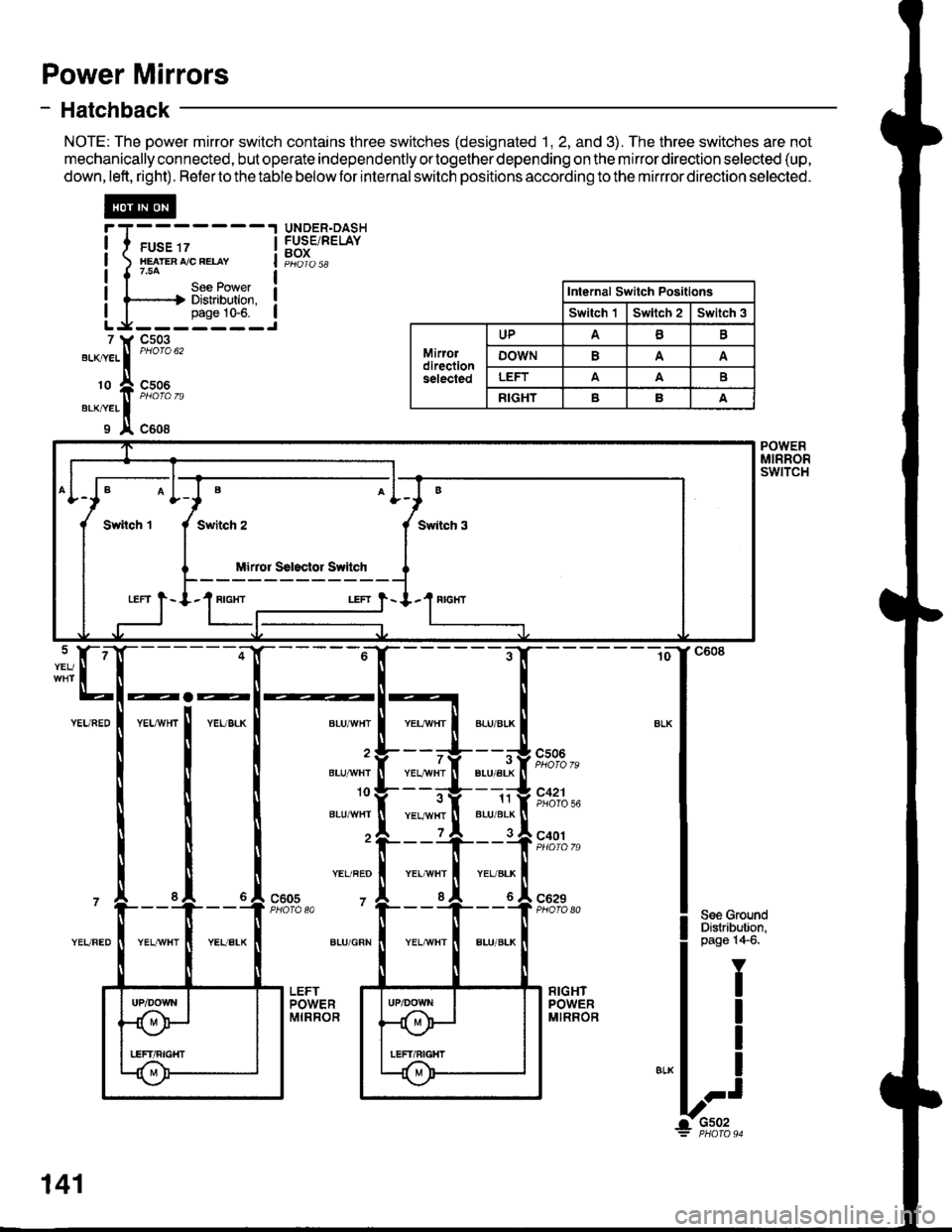
Power Mirrors
- Hatchback
NOTE: The power mirror switch contains three switches (designated 1, 2, and 3). The three switches are not
mechanically connected, but operate independently ortogether depending on the mirror direction selected (up,
down,left, right). Refertothetable belowfor internalswitch positions according to the mirrror direction selected.
@
I I ruse rz I
I xearenrceeuv I
|{754 |I I Uee FOI/ver I! l-----.-.| Distribution. !I I pase 10-6. ILg-------J
UNDER.DASHFUSE/RELAYBOX
7 ll, Cs03
"'-^."..
|
"'otou'
'o ft ffi%,,erxner II x c608
Internal Switch Positlons
Switch 'lSwltch 2Switch 3
Mirordirectionselected
UPAB
oowNA
LEFTAAE
RIGHTBA
B
Swiich 3
Mirror Ssl3clor Switch
LEFT } - I.1 RIGIfI
POWERMIRRORswtTcH
BLU/'WHT
BLU]'IVHI
10
BLU^^/HT
YEL/REO
7
ALU/GRN
YEL/YVHTBLU/ALK
11BLU/BLK
cs06
7
YEL,ryvHTPHOTO 56
c401
c629PHO|O A0c605PHOTA 80
141
Page 1562 of 1681
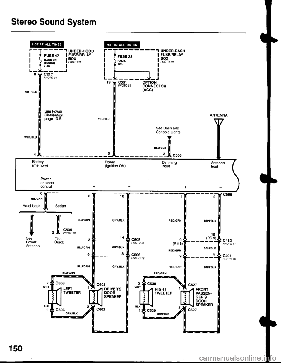
Stereo Sound System
UNDER-HOOD.I UNDER-DASH
I FUSE/RELAYI
I
I
-T',
?j-v,-
:I
rl
I
I
I
8
WH'/BLU
FUSE 28BAO|()roa
L_L____l_J
FUSE 47FUSE/RELAYBOXaacx ug{aao|o)
c217
c551 oPT|ONPHOTA 58 CONNECTOR19 t, C551
See PgwerDistribution,10-8.
10(RS e)
c505
Sodan
It
Itc
(NotUsed)
6 l,-"."'c"" I
Harcnoact j
T_
i
tSee
AntennaCRY/ALK
I
csos
c506
8RN/BLK
I
c452
c401
FRONTPASSEN-GER'SDOORSPEAKER
Battery(memory)
Powerantennaconrol
150
Page 1564 of 1681
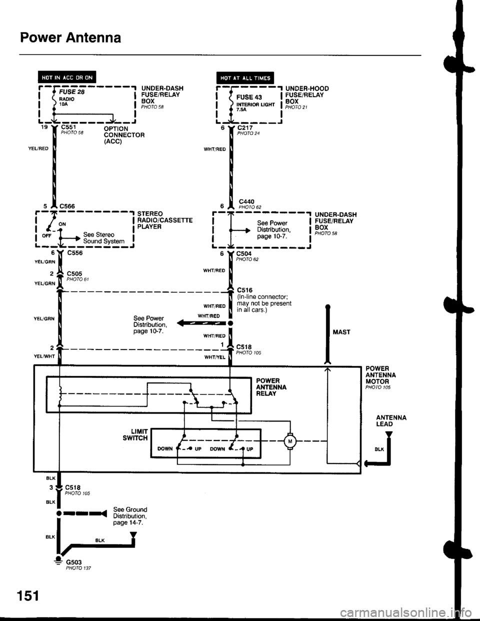
Power Antenna
9_5^s,1 -^ oPloNCONNECTOR(ACC)
c505
UNDER.DASHFUSE/RELAYBOXPHOTO 58
ifsEii'-----'1NAD'O
UNDER-DASHFUSEiRELAYBOXPHOTA 58
STEREORADIO/CASSETTEPLAYER
UNDER-HOODFUSE/RELAYBOX
T--;;--+--{> Distribution,
I__i1':__
f
r*.,
I"."
I
I
I
YEUGBN
2
YEUGFN
l"^"
@.
WHT/BEO
1c5tI
POWERANTENNAMOTOR
ANTENNALEAO
er* I
FJ
c518
See GroundDistribution,page 14-7.
iT;;-r
L-tr:-::i6 Y C217
s A c566
i-I*-------t
I r-i- |
LI-t.-*-3E&"{3::J
151
arrxa
Page 1565 of 1681
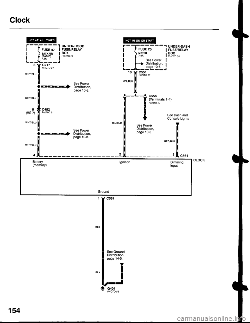
Clock
I
I
8(RS 7)
WHT/BLU
UNDER-HOODruse lz I FUSE/RELAY
lragr-lle I Pg^I^ ^
{f*'o, a PHafo 21
c2'17
aaaQ
c452
aaaa)'
"-,,[r*"
nnT,i"".'-.)
I
Y
See PowarDistribution,page 10-5.
r--I------1 UNDER-DASHI f FUSE2S I FUSE,RELAY
a J y5t* a"';L,,
| | See Power l
r f+ ?:"i:q*t:"' IL--9,-.-=:-:J10 Y C551
8
WHT/BLU
WHT/BLU
See PowerDistribution,page 10-8.
WHT/BLU
See PowerDistribution,page 10-8.
See Dash andConsole Lights
T
I
"ao,"a* f
--J"*'
CLOCKBattery(memoryJlgnitionDimminginput
Ground
1 Y C561
',54
Page 1566 of 1681
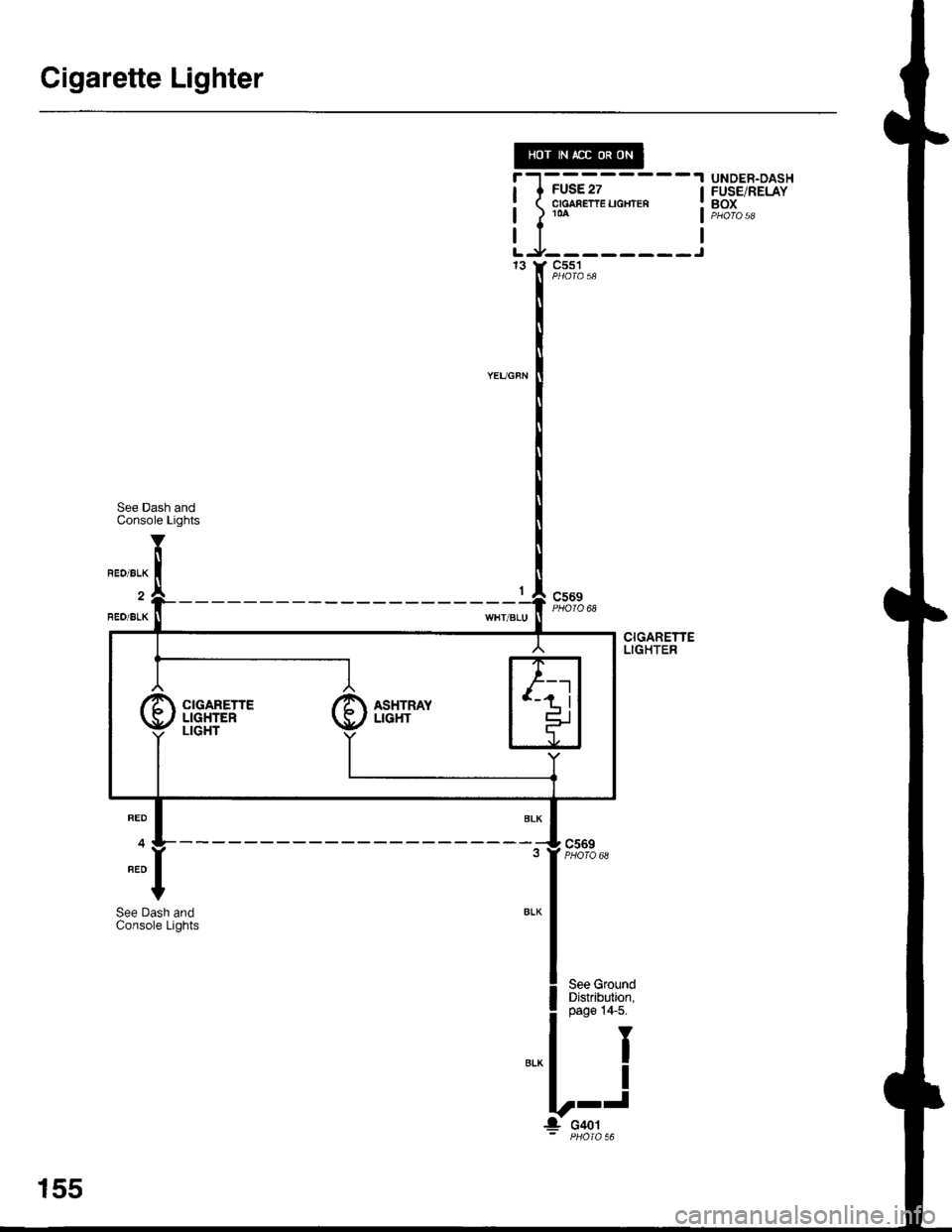
Cigarette Lighter
iltt-"--- _-j" r F,*%*
UNDER.DASHFUSE/RELAYBOX
See Dash andConsole Lights
BED/BLK
FEO/BLK
c569PHOIQ 68
c569PHOTO 68
CIGARETTELIGHTER
RED
4
BED
See Dash andConsole Lights
I
I
J
CIGARETTE /E ASHTRAY
155
J o+ot
Page 1570 of 1681

)-
)-
19. Right Side of Engine22. Right Hear Corner of Engine Compartment
20. Right Side of Eng. Comp. (A/I Shown, lvVT Similar)
c104(6-GRY) (RS, LSAND GS WITH A,IT)(3-GRY) (GS-R, TYPE-F)
23. Right Rear Corner of Engine Compartment
21. Right Rear Corner of Engine Compartment24. Underside ot Under-hood Fuse/Relay Box
l.
201-3
Page 1577 of 1681

Component Location
61. Behind Dashboard Lower Cover
65, Behind Dashboard Lower Cover
rt-
64. Behind Dashboard Lower Cover
SRS MEMORYERASE SIGNAL(MEs)CONNECTORc808(2-YEL)
62, Rear of Under-dash Fuse/Relav Box
63. Behind Dashboard Lower Cover
201-10
66. Behind Dashboard Lower Cover
l,l -
Page 1596 of 1681
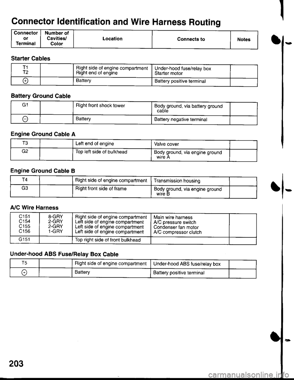
Connector ldentification and Wire Harness Routing
Connector
OT
Terminal
Number of
Cavities/
Color
LocationConnecls toNotesI
fl-
Starter Cables
T1
T2Right side of engine compartmentRight end of engineUnder-hood fuse/relav boxStarter motor
oBatteryBattery positive terminal
Battery Ground Cable
lRight front shock towerBodyground, via battery ground
ABatteryBattery negative terminal
Engine Ground Cable A
T3Left end of engineValve cover
Top left side ol bulkheadBody ground, via engine ground
Engine Ground Cable B
T4Right side of engine compartmentTransmission housing
Right front side of trameBody ground, via engine ground
wrre b
A,/C Wire Harness
Under-hood ABS Fuse/Relay Box Cable
203
c151
c'154utSc
u tco
8-GRY
2-GRY
2-GRY
1-GRY
Right side ol engine compartmentLeft side of engine compartmentLeft srde of engine compartmentLeft side of engine compartment
Main wire harness
A'lC pressure switch
Condenser tan motorA,/C compressor clutch
lrlclTop right side ot front bulkhead
T5Right side of engine compartmentUnderhood ABS fuse/relav box
\,BatteryBattery positive terminal