ground HONDA INTEGRA 1998 4.G Workshop Manual
[x] Cancel search | Manufacturer: HONDA, Model Year: 1998, Model line: INTEGRA, Model: HONDA INTEGRA 1998 4.GPages: 1681, PDF Size: 54.22 MB
Page 1525 of 1681
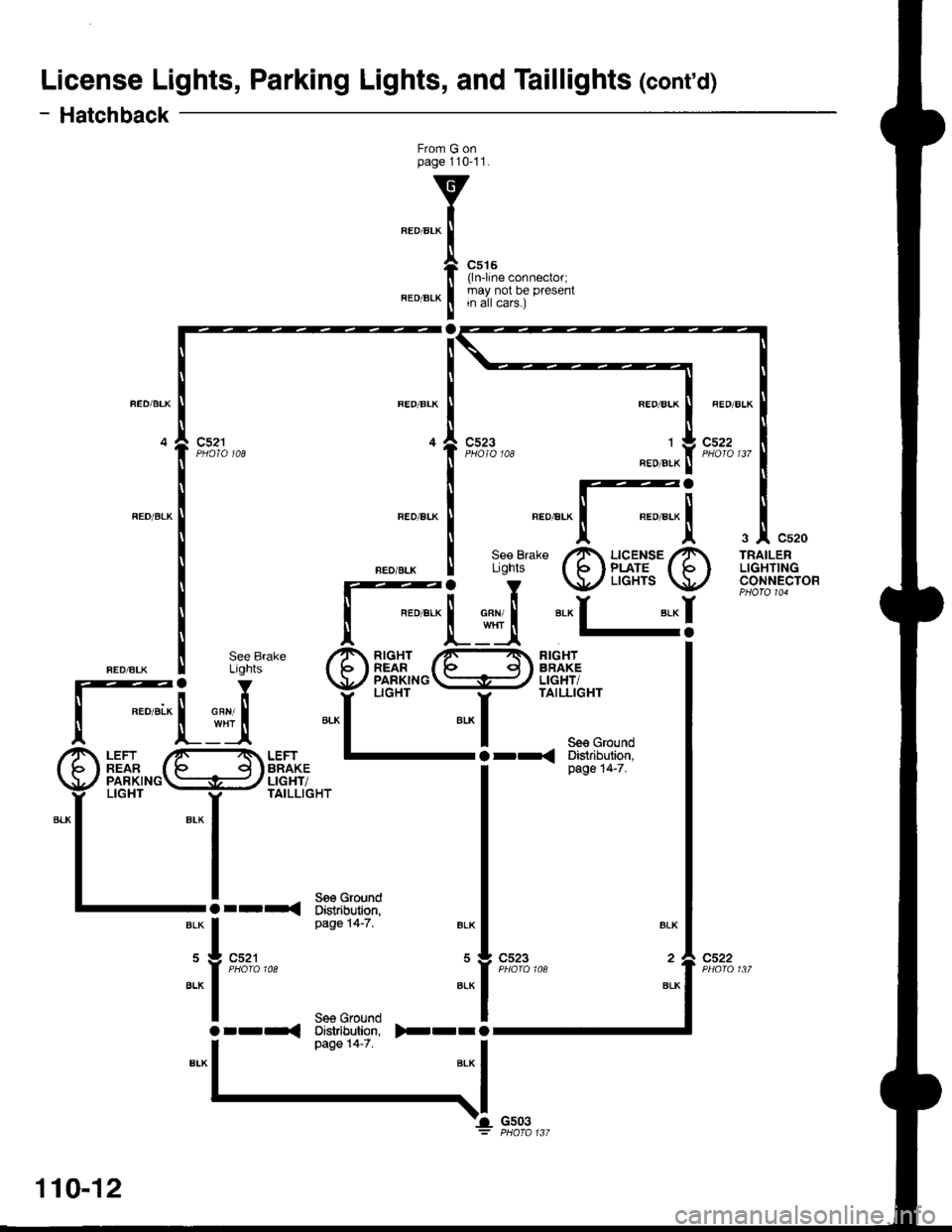
License Lights, Parking Lights, and Taillights (cont'd)
- Hatchback
From G onpage 110'11.
REO/BLK
la
c515(lnline connector;may not be presentin all cars.)
c523
RED/BLK
,l
BEO/B!K
c522
"_^.[-[
3|' Cs20
TRAILERLIGHTINGCONNECTOR
rL.4
Or-r
il
BLK
BLK
c522
Se€ GroundDistribution,page 14-7.)rrr
BLK
110-12
o--r<
'-l Gs03
Page 1526 of 1681
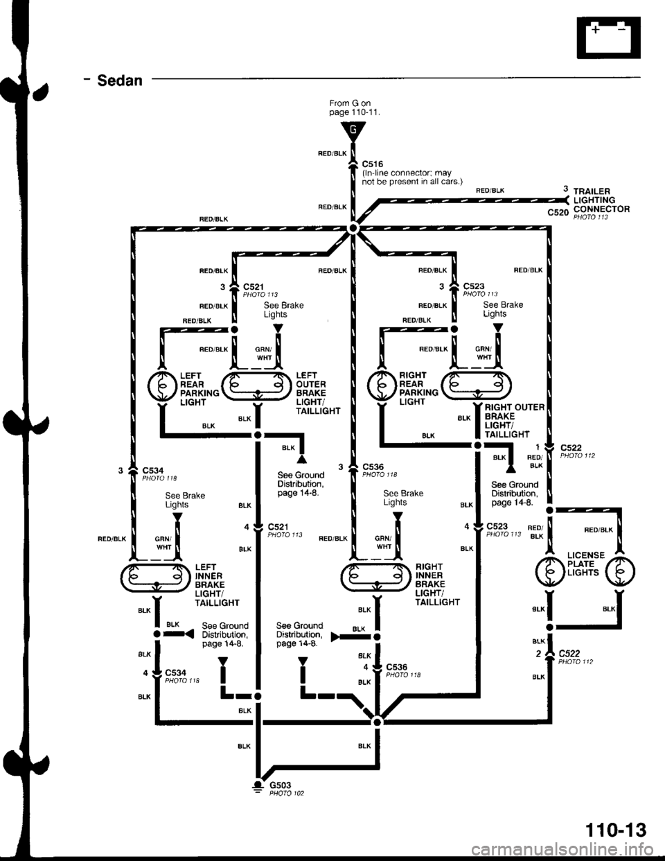
- Sedan
Frorn G onpage 110-11.
c516(ln line connector: maynot be present in all cars.)
FEO/BLK
3
FED/BLK
FED/ALK
c521
See BrakeLights
REO/BLK
FEO/BLK
NED/BIK
See Brake
3 tnatLenLIGHTINGnqrn CONNECTOR
cs22
c522
FLuiRIGHTREARPARKINGLIGHT
BLK
*-li,fr,t;;'-
FI
Sge GroundDistribution,
1BED/BLKc536
c521
ritr
INNERBRAKELIGHT/TAILLIGHT
RIGHTINNERBRAKELIGHT/TAILLIGHT
LICENSEPLATELIGHTS
*-r
a
ALK
BIK See Groundr< Distribution,S€s GroundDistributign,page 14-8.
V
I
".":^l>-o
"'fI
".*f
"^IJ
page 14-8.
Y
,"rt:A r* I
BLK
c536
L-
110-13
Page 1531 of 1681
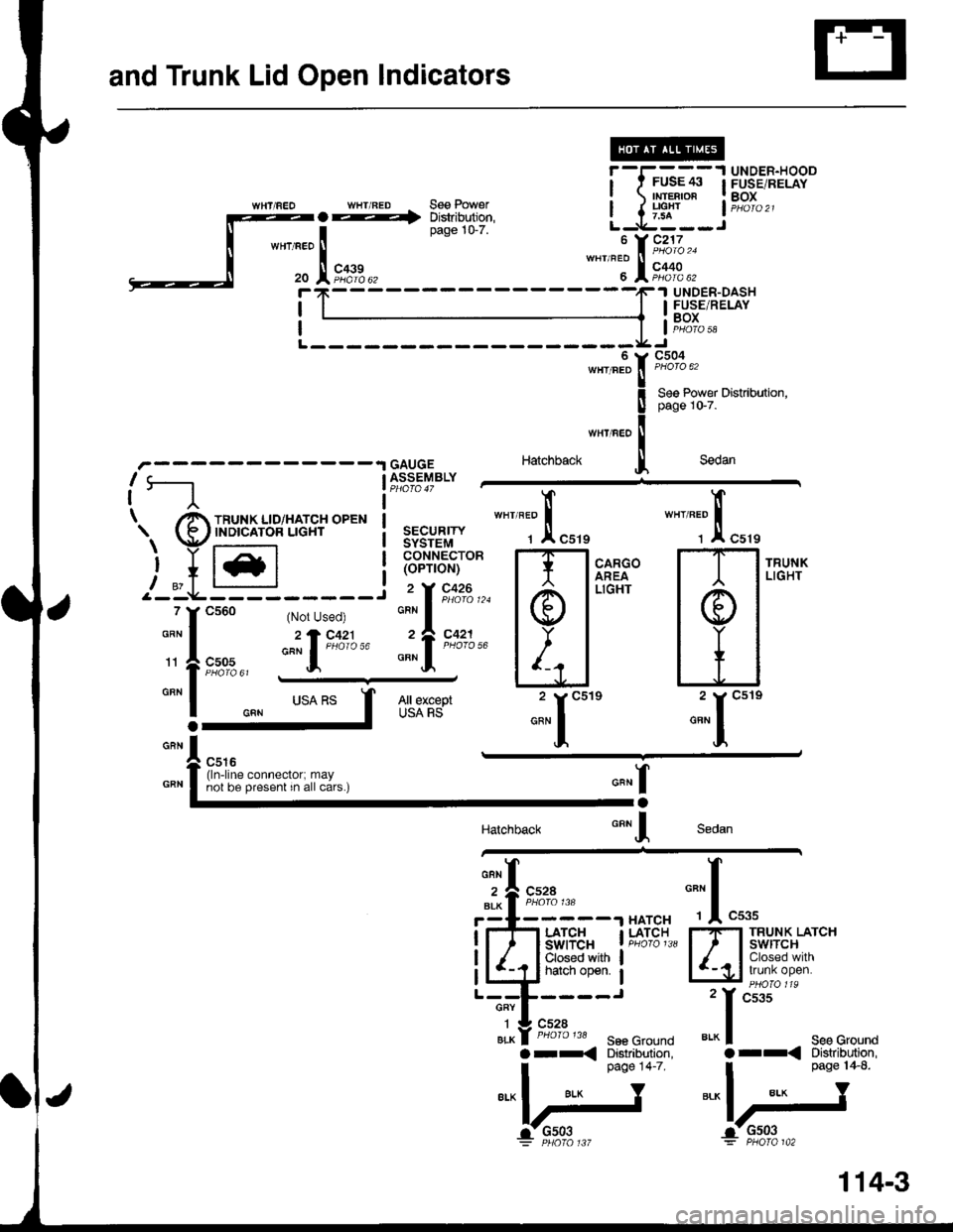
and Trunk Lid Open lndicators
i-I-'-*,* lP$3..,9'll?9"
rg::::l-^'..*"'"*.* *,:t?::: i ) ffiF*'" l?,oI.,,wHT/FEo WHT/FED See Power
:fJfi:::
r -I-- - -'l UNDER-HOOI t FUSE/$ | FUSE/RELAY! rMr€BroR lBox
I { |9i" lPHoro2lL-g---Ju Y 9i;,'",,,wHt/Feo ll
u l?,o.ol. *_____,F.| UNDER_DASH
I I I IE*9E;RELAY
; I li,z?o,a
c504
Hatchback
Se6 Power Distribution,psge 10-7.
Sedan
I
I
\
GAUGEASSEMBLY
SECURITYSYSTEMCONNECTOR(oPT|ON)
"-l;;,
*"''"t"f,
"u*
""''"',"
X "ut,
*:"1*"":"1*"
Sedan
o"n I
'1.
All exceptUSA RS
Ia
IHatchback
r_t_____.l HATCHLATCHswtTcHClosed withhatch open.
LATCH
5€6 GroundDistribution,page 14-7.
TRUNK LATCHswtTcHClosed withtrunk open.
See Ground
i-- 3:uii3:
"l.r#J
BLK
(ln-line connector; maynot be present in all cars.)
a-<
114-3
Page 1532 of 1681
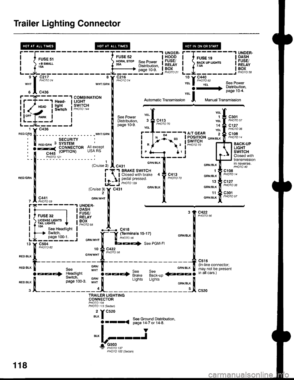
Trailer Lighting Connector
rl;:'
H***
', J "' o, "'oto'o
; -
l-
- - - - - -
iiiJnlw
,i%*,*:l Y* | L-i+--.r tdl##i*
I (c,uise ir I 6a31- ..._ -....__::"
*-
| ."u ", * [ in reverse.
u iti!ms..:y'I'9|| .["...
- -l*s;.,g,."'""
,",0:;"* *";,1 I "*'"tt-fiF'1%"
FUSE32 | i:gPfu [ '89"'::.,"
ili'*'U"T*.,t,., !Fst., J--. .0,.
l[r!g:_l """*",f-l g:lTinars 1s-17)
;04 [ ba{ See PGM-FI)ro 62 fi A cczz
".":.:Xt*" """,,J"',it'*'**=
.EE4 :e?d,,!h,
""' i-:.+ 9t= 9:9___- €::5 ;;;irc;;ai
".o".* | il',iii'1t.. $11 |
Lisnii Lb;i;' o"n,.* |
. JL-----------1JI- ljl c'ro
TRAILER LIGHTINGCONNECTOR
2 Y Cs20BLX I - See Ground Drstnbutron,Orrr{ Oaqe r4-7 or 14-6.T-IY"," I I--'I^-rrr-
r:-910,3,.,,
PHOIO 102 lsedanl
5 A C435 | ver- | IrcsE rv-q
if:T---r J;l l-'!ti^*t" I oromaticrransmission I Manuarrransmission
ll(':'iis,i'"nl;*ri"* i ffi
i l#.1"-"
I sw*ch ' Piu''J 'r
L*'**r*,
"]l
"*. "iU t*.,
L'_-_L-_-_'___..!
".o 0,," l( "o.u I
o"o" to-s
_:l_____ 1,!,| ,";:,'","
"'""i'!;
:isr"H"" ^; j""":"" t []t lil?lfililr
""""ff*:;
Lfl6ti*-" i--g-----J
F T'I BRAKE SWITCH TI
Ilj iiifl'#'!"';l-"' tr
""#"3 "
lf c431 GRN/BIK
I
it
*)ir;***"{:"- [:**"
"":r[;;,,
-",*l"Y ""#B'' J.l1nqi, se€Power
.-3:i!i,Jil
I swllch I PH(,,/ci r44
! ,"" ,o*", "ttl "T
U .rot
8 Y C216
il-l-
118
Page 1534 of 1681
r-T--------.lUNDER.
I t FUSE46 IHOODi PovrER iFUSEt! I glDow ! RELAYI I* lBoxL_ rfa __ ___ ___J DtlOrO 2l
'l( ?i:L,,wHr/BLU IN C4396 A PHoro 62
:;I
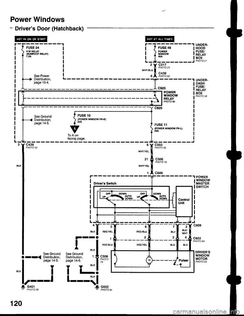
Power Windows
- Driver's Door (Hatchback)
I
Jffi;-----
f
l*n"oo"""-n
I
I ,"" ro*",
f4 Distribution,
L_il"_j___
UNDER-DASHFUSE/RELAYBOX
_t;'-----tPOWERwtNDowBELAY
See GroundD islribution,page 1+5.
c925
FUSE 11{POWEn wlt{DOW rF-I)
c439PHO|O 62c503PHOTO 62
cs06
c609
POWERwtNDowMASTERswtTcH
--------1
Drive/8 Swllch
2BLr./
4
7
BLU
3c603
DRIVER'SwtNDowMOTOR
See GroundDistribution,page 14-5.
Y
I
-l
lrr{
".* I
lllt--
120
Page 1536 of 1681
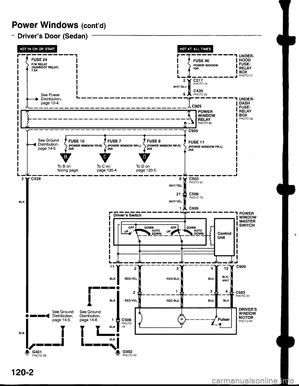
Power Windows (cont'd)
- Driver's Door (Sedan)
See GroundDistribution,page 14-5.
FUSE 10(POWEF Wrf{rOW rB€)20A
FUSE 7(FOWEA WTNOOW FB-L)204
FUSE 8{FOWEB WTNOOW Fi.F)
UNDER.HOODFUSE/RELAYBOX
UNDER-DASH
RELAYBOX
POWERwtNDowMASTEBswrTcH
i-l;;;----l
t-l::-::---i, t( Fi;/.,"*"'"1,!,
F,i';.,
BLIq
IL
-rffi;-----
f
*"oo'"'-'
I
| ,"" ro'n",
l----t Distribution,
L_i1"1'l____f;-----lPOWERwlt'IDOWRELAY
c925
FUSE 11(POWER WINDOW FF-L)204
--------Jc503
c506
toLjontacing page.touonpage 12G4.ToDonpage 120"5.
r-
l-
I
_t_
::,:1[
c609
l-fiu?'isiii-"r'--
8LU
.__,
FEO,^VEL
RED]YEI
.."^ [;;,;io I"t.
G502PHATO 91
L1
""I
ra
""1
.1.
"*rt
ra
\1,
ALK
III
BLK
Ind)n,3. 1
Y BLK
l-BLK
IIl.
1
I
See GroundDistribution,Daoe 14-6.
See GIlDistrib!page 1,
I
l--l
I
c603
See GroundDistribution,page 14'5.
Y
I
DRIVER'SwtNDowMOTORc506Orr{
".* I
llt--
-r- u4ul
I
120-2
Page 1538 of 1681
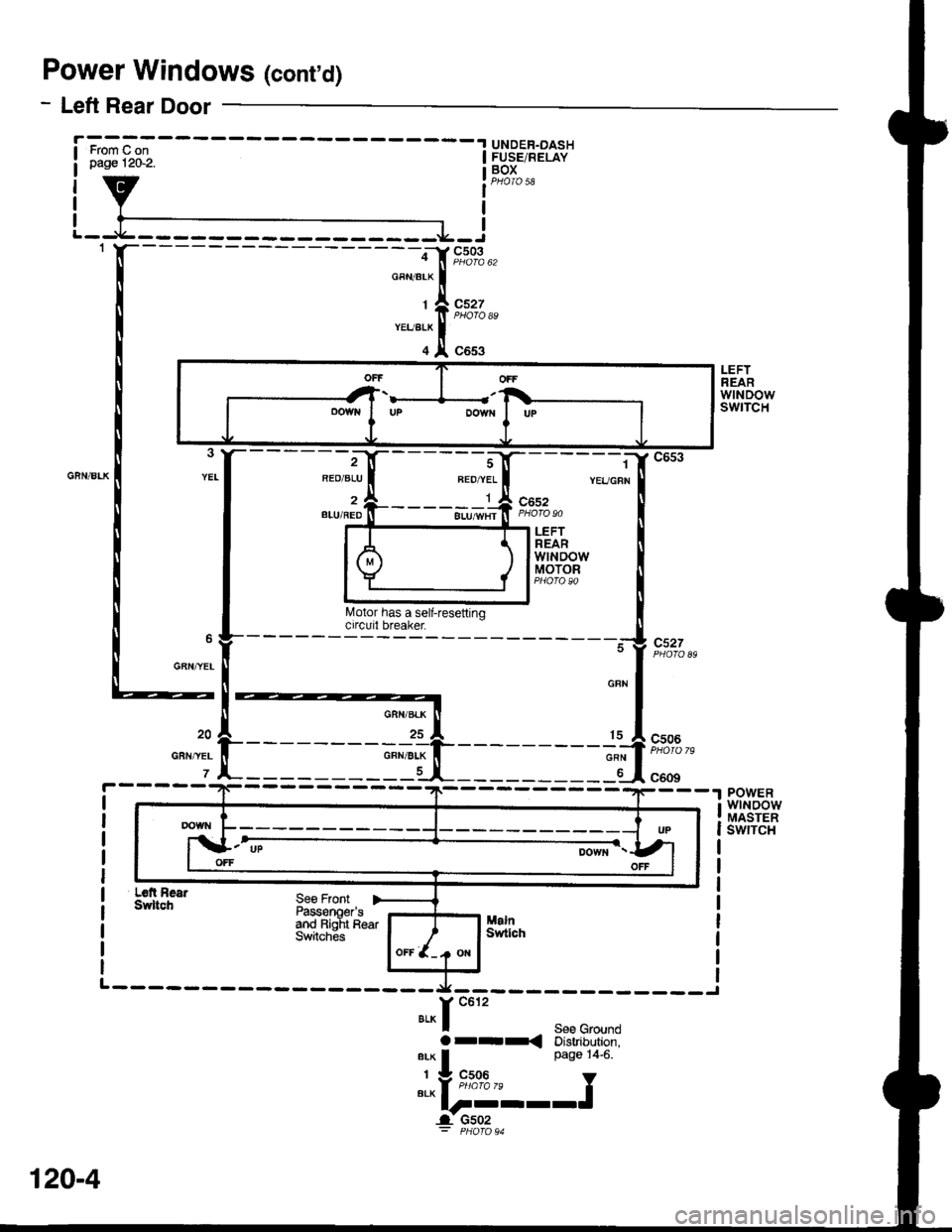
Power Windows (cont'd)
- Left Rear Door
UNDER-DASHFUSE/RELAYBOX
I
cs03
c527
c653ffi
LEFTREARwtNDowswtTcH
REO/ALU
l
2BLU/REDc652
c527
LEFTREARwtNDowMOTOR
GAN,YEL
c506
c609POWERwtNoowMASTERswrTcH
Ldt AearSwltchSee FrontPassonoer'sand Bialt R€arSwitches
-.x---------- ____J
Y c612
BLK I See GroundOr-r< Distribution,arx I Page 14-6.
' v "c;0*," Y"t"l-----J
_l u5uz
OFFOFF
oowNDOWfIUP
120-4
Page 1539 of 1681
![HONDA INTEGRA 1998 4.G Workshop Manual - Right Rear Door
UNOER.DASTIFUSE/RELAYBOXFrom D onWge 1262.
I
c503
c528
;-:;[
*""T.!.
RIGHTREARwtNoowswtTcH
c658
{----:r"il-;, {
[6]lrs;n Il\,4otor has a sell-resetting ll
------"atg""g-----
#
-, HONDA INTEGRA 1998 4.G Workshop Manual - Right Rear Door
UNOER.DASTIFUSE/RELAYBOXFrom D onWge 1262.
I
c503
c528
;-:;[
*""T.!.
RIGHTREARwtNoowswtTcH
c658
{----:r"il-;, {
[6]lrs;n Il\,4otor has a sell-resetting ll
------"atg""g-----
#
-,](/img/13/6069/w960_6069-1538.png)
- Right Rear Door
UNOER.DASTIFUSE/RELAYBOXFrom D onWge 1262.
I
c503
c528
;-:;[
*""T.!.
RIGHTREARwtNoowswtTcH
c658
{----:r"il-;, {
[6]lrs;n Il\,4otor has a sell-resetting ll
------"''atg""g-----
#
-,
i
- - - - - - - -
-j:,r
- - - - - - - - :'$]
c528
c506
c609
19
YEL
16POWERwtNDowMASTEBswtTcH
Right RearSwitchSe€ FrontPagsenoer'sand Lefi'RearSwitches
".^f "tt'
See Groundarrd Distribution,
".* | Page 1+6
.:.Y "",X'3- I---l1lt----t
I :c-u_z^ ^.
---l'>DOWN I UP
.-'T!ootluP
OFFOFF
120-5
Page 1540 of 1681
Power Windows (conrd)
- How the Circuit Works
CAUTION: You could iniure your arms, hands,
or fingers if you unintentionally switch the
driver's window to "automatic down,' while
working in that door with the power on. Discon-
nect the window switch connector or the battery
when working in the driver's door.
System Description
The operation of the power windows is controlled by
the main switch in the power window masler switch.
When the main switch is in OFF, only the driver's
door window can be opened or closed. With the main
switch ON, all windows can be opened or closed
either by switches in the master panel, or switches in
the doors. The driver's window switch also has an
automatic down mode which is tumed on by pushing
the switch down to its second position.
The power windows are driven by reversible motors.
Each motor is protected by a built-in circuit breaker.
lf the window switch is held on too long (with the
window obstructed, or after the window is fully up or
down), the circuit breaker opens the circuit. The
circuit breaker resels automaticallV as it cools.
Driver's Window
With the ignition switch in ON (tt), vottage isprovided to the coil ol the power window relay
through fuse 24. The contacts of the power window
relay close, and voltage is applied to the driver's
switch. When you push the power window master
switch to Uq voltage is applied to the driver's power
window motor. (The motor's ground path is backthrough the power window master switch.) The
driver's window motor then drives the window uo.
When you push the switch to DOWN, voltage ls
applied in the opposite direction and the motor
drives the window down.
Automatic Down (Driver's Window)
With the ignition switch in ON (tl), vottage is applied
to the coil of the power window relay. The contacts
of the power window relay close and voltage is
applied to the power window master switch. When
you push the driver's switch to the AUTO DOWN
position, voltage is applied through the drivels
switch to the driver's window motor. The control unit
receives pulses at the pulser input while the motor
is running. When the window is fully down, the
motor stops, and pulses are no longer generated by
the pulser. This is sensed by the control unit at thepulsBr input, and voltage is no longer applied to the
driver's window motor.
Passenger Windows
With the ignition switch in ON (tt), vottage is apptied
to the coil of the power window relay through fuse
24. The contacts of the power window relay then
close, applying voltage to the individual window
switches and the power window master switch. With
the master panel main switch ON, the passenger
windows can be operated from the individual
window switches or from the master Danel switches.
When you push the front passenger's window
switch to UR voltage is applied to the front
passenger's window motor. (The motor is grounded
through the contacts in the front passenger's window
switch and the power window master switch.) The
wndow moves up as long as you hold the switch in
lhe UP position. lf you push the switch to DOWN,
voltage is applied in the opposite direction io the
front passenger's window motor, and the window
moves down as long as you hold the switch in the
DOWN position. The window switches in the other
doors operate similarly.
When you push the front passenger's switch in the
master panel to UP, voltage is applied through the
front passengeas window switch contacts to the
front passenger's window motor (The motor is
grounded through the contacts in the front
passenger's window switch and the power window
master switch.) The window moves up as long asyou hold the switch in the UP position. lf you push
the switch to DOWN, voltage is applied in the
opposite direction to the front passenger's window
motor, and the window moves down as long as you
hold the switch in the DOWN position. The otherpassenger window switches in the master panel
operate similarly.
Refer to the Service Manual (Section 23, Electrical)
for specific tests or troubleshooting procedures.
120-6
Page 1542 of 1681
- How The Circuit Wo
With the ignition switch ON (ll), voltage is applied
through fuse 24 to the coil of the moonroof relay.
The moonroof relay energizes and voltage is
applied from fuse 49 through the closed contacts of
the moonroof relay to the moonroof switch.
Open Operation
When you push the moonroof switch to the OPEN
position, voltage is applied to the moonroof motor.
The moonroot motor is grounded through the
CLOSE contacts of the moonroof switch, and the
motor runs to open the moonroof
Close Operation
When you push moonroof switch to the CLOSE
position, voltage is applied to the moonroof motor.
The moontoof motor is grounded through the OPEN
contacts of the moonroof switch, and the motor runs
to close the moonroof.
Refer to the Service Manual (Section 23, Electrical)
for specific tests or troubleshooting procedures.
122-1