ECU HONDA INTEGRA 1998 4.G Owner's Manual
[x] Cancel search | Manufacturer: HONDA, Model Year: 1998, Model line: INTEGRA, Model: HONDA INTEGRA 1998 4.GPages: 1681, PDF Size: 54.22 MB
Page 506 of 1681
uJ
14-89
Ma i nshaft/Cou ntershaft
Speed Sensors
Replacement
l.
2.
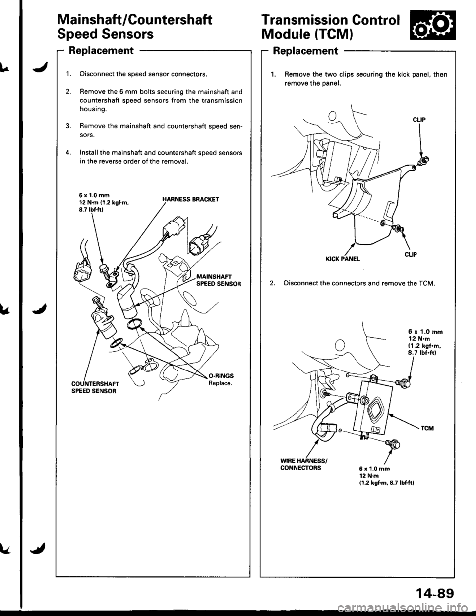
Disconnect the speed sensor connectors.
Remove the 6 mm bolts securing the mainshaft and
countershaft speed sensors from the transmission
housing.
Remove the mainshaft and countershaft speed sen-
sors.
Installthe mainshaft and countershaft speed sensors
in the reverse order of the removal.
6x1.0mm12 N.rn 11.2 kgtm,8.7 tbttrt
Transmission Control
Module (TCM)
Replacement
1. Remove the two clips socuring the kick panel, then
remove the oanel.
2, Disconnect the connectors and remove the TCM.
6 x 1.0 rnm12 N.m{1,2 kgt.m,8.7 tbt.ft)
CONNECTORS
Page 516 of 1681
Pressure Testing
a While testing, be careJulot the rotating front wheels.
a Make sule litts, iacks, and safety stands are placed
properly (see section 1).
CAUTION: Befoie testing, be sure the transmission fluid
is filled to the proper level.
'1. Raise the vehicle {see section 'll.
2. Warm up the engine (the radiator fan comes on),
then stop the engine and connect a tachometer.
3. Connect the special tool to each inspection hole(s).
TOROUE: 18 N.m l1-8 kgt.m, 13lbf.ftl
CAUTION: Connect the A/T pressure gauge secure-
ly, be sure not to allow dust and olher foreign pani-
cles to enter the inspection hole.
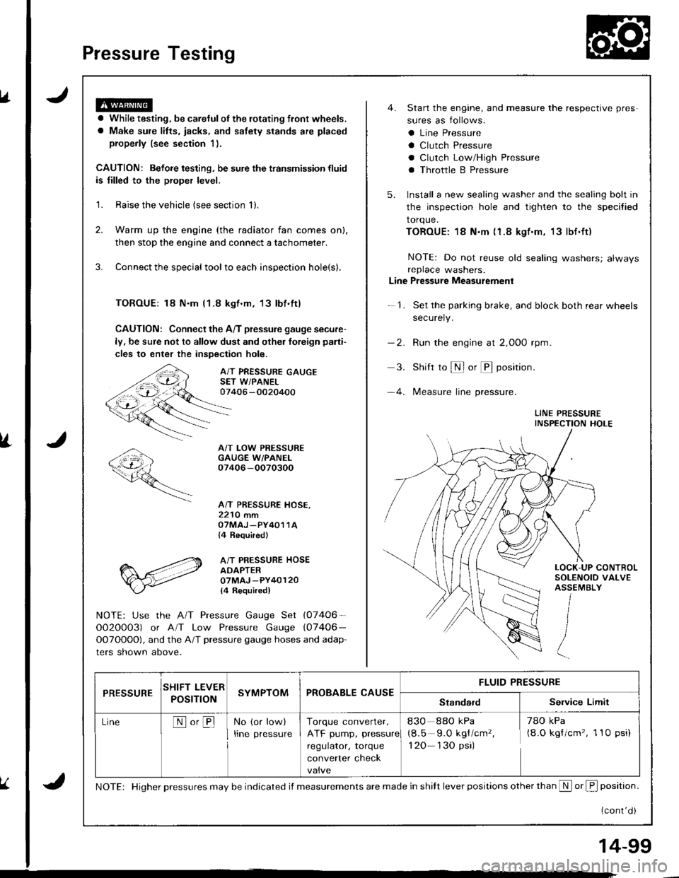
A/T PRESSURE GAUGESET W/PANEL07406 -0020400
A/T LOW PRESSUREGAUGE W/PANEI.07406-OO70300
A/T PRESSURE HOSE,2210 mmOTMAJ _PY4O1 1A{4 Required}
A/T PRESSURE HOSEADAPTER07MAJ -PY40120
l4 Requiredl
NOTE: Use the A/T Pressure Gauge Set (07406-
OO2O0O3) or A/T Low Pressure Gauge (07406-
OOTOOOO), and the A/T pressure gauge hoses and adap-
ters shown above.
4. Start the engine, and measure the respective pres
sures as follows.
a Line Pressure
a Clutch Pressure
a Clutch Low/High Pressure
a Throttle B Pressure
5. Install a new sealing washer and the sealing bolt in
the inspection hole and tighten to the specified
torque.
TOROUE:18 N.m (1.8 kgf.m, 13lbf.ft)
NOTE: Do not reuse old sealing washers; alwaysreplace washers.
Line Pressure Measurement
-1. Set the parking brake, and block both rear wheels
securely.
-2. Run the engine at 2,000 rpm
3. Shift to S or @ position.
4. lMeasure line pressure.
LINE PRESSUREINSPECTION HOLE
LOCK-UP CONTROLSOLENOID VALVEASSEMBLY
PRESSURESHIFT LEVER
POST ONSYMPTOMPROBABLE CAUSEFLUID PRESSURE
StandardService Limit
LineNo,BNo (or low)
Irne pressure
Torque converter,
ATF pump, pressure
regulator, torque
converter check
830 88o kPa
(8.5 9.O kgf/cm'�,
1 20 130 psi)
78O kPa(8.O kgf/cm'�, 1 10 psi)
NOTE: Higher pressures may be indicated if measurements are made in shitt lever positions other than S or f, position.
{cont'd )
14-99
Page 517 of 1681
Pressure Testing
.Y
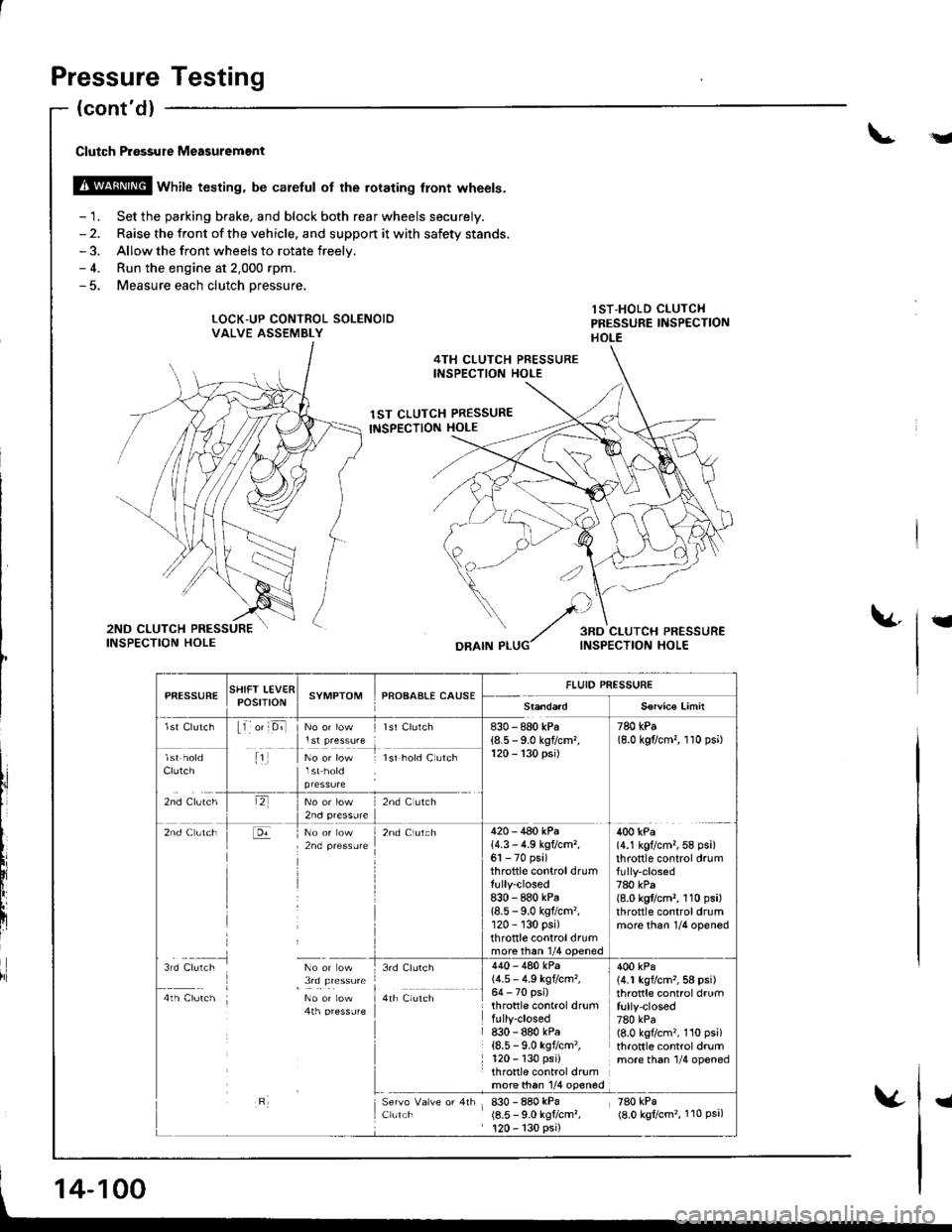
Clutch P.6ssure Measuremgnt
@ wnirc testing. be caretul ot the rorating tront wheels.
- 1. Set the parking brake, and block both rear wheels securely.- 2. Raise the front of the vehicle, and support it with safety stands.- 3. Allow the front wheels to rotate freelv.- 4. Run the engine at 2.000 rpm.- 5. Measure each clutch oressure.
LOCK"UP CONTROL SOLENOIDVALVE ASSEMBLY
lST-HOLD CLUTCHPRESSURE IiISPECTIONHOLE
4TH CLUTCH PRESSUREINSPECTION HOLE
1ST CLUTCH PRESSURE
INSPECTION HOLE
t
DRAIN P
l,i
PfiESSURESTIIFT LEV€RPOStTtONSYMPTOMPROAAALE CAUSEFLUID PRESSURE
S€rvico Limit
lst Clutch11 o' D;llst Clurch830 - 880 kPa(8.5 - 9.0 kgflcm,120 - 130 psi)
780 kPa(8.0 kgflcm,, 1 10 psi)
Clutch
zno cruiltr
1No or low lsr hold C utch
lr,2nd C ltch
2nd Clutch420 - 440 kPa14.3 - 4.9 kg?cm,,61 - 70 psi)throttle controldrumtully-closed8:|0 - 880 kPa18.5 - 9.0 kgflcm'�,120 - 130 psi)throttle controldrummore than 1/4 ooened
400 kPa(4.1 kg?cm,,58 psi)throttle control drum
780 kPa(8.0 kgflcm,, 110 psi)throttle controldrummore than 1/4 opened
3rd Clulch No or ow
I , !,q !le"**4th Clutch No or Low4th pressufe
3rd Clurch
a,r il","r,
Clulch
440 - 480 kPa(4.5 - 4.9 kgtcm,,64 - 70 psi)throttle control drumfully-closed830 - 880 kPa{8.5 - 9.0 ksf/cm'�,120 - 130 psi)throttle control drumrn9l9!q l/4 olqg
830 - 880 kPa(8.5 - 9.0 kgtcm?,120 - 130 psi)
400 kPa14.1 kgvcm,,58 psi)throttle control drumfully-closed780 kPa(8.0 kgflcm'�, 110 psi)throttle control drummore th6n 1/4 opened
zeo rpi(8.0 kgtcm'�, 110 Psa,
14-100
I
Page 532 of 1681
I
t
I
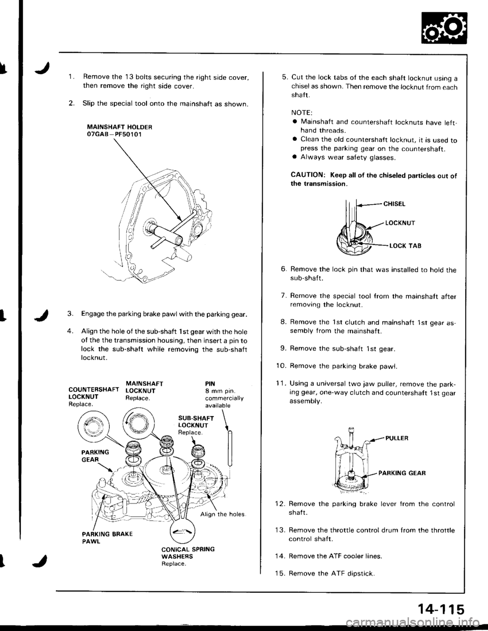
1.
2.
Remove the 13 bolts securing the right side cover,
then remove the right side cover.
Slip the special tool onto the mainshaft as shown.
MAINSHAFT HOLDEROTGAB PFsO1O1
Engage the parking brake pawl with the parking gear.
Align the hole of the sub-shaft 'lst gear with the hole
of the the transmission housing, then insert a pin to
lock the sub-shaft while removing the sub-shaft
locknut.
MAINSHAFTCOUNTERSHAFT LOCKNUTLOCKNUT Reptace.Replace.
PIN8 mm pin.
commerciallyavailable
SUB.SHAFTLOCKNUTReplace.
Align the holes.
CONICAL SPRINGWASHERSReplace.
5. Cut the lock tabs oI the each shaft locknut using achiselas shown. Then remove the locknut from eachshatt.
NOTE:
a lvlainshaft and countershaft locknuts have left,hand threads.
a Clean the old countershaft locknut, it is used topress the parking gear on the countershaft.a Always wear salety glasses.
CAUTION: Keep all of the chiseled paiticles out ofthe transmission.
ll fcH,sEL
Jl{*---,o"*",r
@--.**,o,
6. Remove the lock pin that was installed to hold thesub-shaft.
7. Remove the special tool from the mainshatt afterremoving the locknut.
8. Remove the 'lst clutch and mainshaft 'lst gear assembly from the mainshaft.
9. Remove the sub-shaft 1st gear
10. Remove the parking brake pawl,
11. Using a universal two jaw puller, remove the park-
Ing gear, one-way clutch and countershalt 1st gear
assemoty.
PARKING GEAR
brake lever from the controlRemove the parking
shaft.
Remove the ATF cooler lines.
Remove the ATF dipstick.
13. Remove the throttle control drum lrom the throttle
control shaft.
14.
t5.
14-115
Page 534 of 1681
fNOTE:
a Clean all parts thoroughly in solvent or carburetor
cleaner and dry with compressed air.a Blow out all passages.
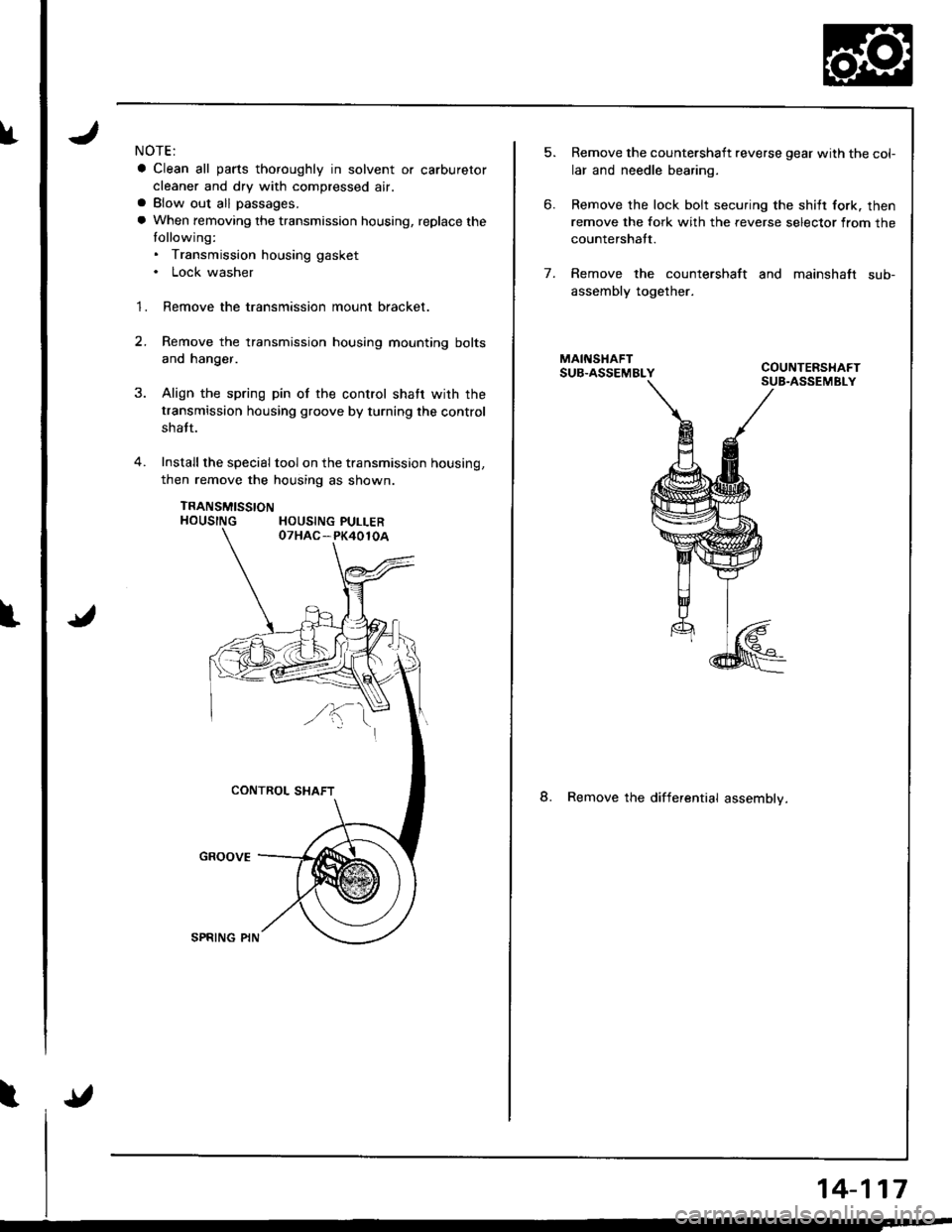
a When removing the transmission housing, replace the
tollowing:. Transmission housing gasket. Lock washer
1. Remove the transmission mount bracket.
2.Remove the transmission housing mounting bolts
and hanger.
Align the spring pin of the control shatr wirh the
transmission housing groove by turning the control
shatt.
Install the special tool on the transmission housing,
then remove the housing as shown.
TRANSMISSTONHOUSING HOUSING PULLER
5.
6.
Remove the countershaft reverse gear with the col-
lar and needle bearing.
Remove the lock bolt securing the shilt fork. then
remove the fork with the reverse selector from the
countershatt.
Remove the countershaft and mainshaft sub-
assembly together.
8. Remove the differential assemblv.
7.
14-117
Page 536 of 1681
I
l"
I
J
NOTE:
a Clean all parts thoroughly in solvent or carburetor
cleaner and dry with compressed air.
a Blow out all passages.
a When removing the valve body replace the lollowing:. O-rings. Lock washers
1 . Remove the ATF feed pipes from the servo body, ser-vo detent base, accumulator cover, lock-up valve
body and main valve body.
2. Remove the three bolts securing the ATF strainer
and servo detent base, then remove the strainer
and detent base.
3. Remove the three bolts securing the accumulator
cover, then remove the accumulator cover.
4. Remove the six bolts securing the servo body. then
remove the servo body and separator plate.
5. Remove the one bolt securing the secondary valvebody, then remove lhe secondary valve body andseparator plate.
6. Remove the eight bolts securing the lubricator plate
and lock-up valve body, then remov€ th€ lubricator
plate. Iock-up valve body, and separator plate.
7. Remove the one bolt securing the regulator valve
body, then remove the regulator valve body.
8. Remove the stator shaft and stop shaft.
9. Remove the detent spring from the detent arm, then
remove the control shaft from the torque converter
housrng.
1O. Remove the detent arm and detent arm shatt from
the main valve body.
1 'l . Remove the four bolts securing the main valve body,
then remove the main valve body.
'I2. Remove the ATF pump driven gear shatt, then re-
move the ATF pump gears.
13. Remove the main separator plate with two dowel
pins.
15.
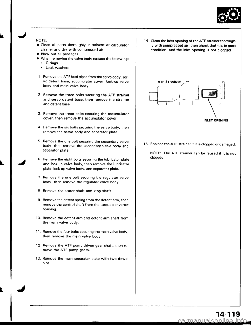
14. Clean the inlet opening ot the ATF st,ainer thorough-
ly with compressed air, then check that it is in good
condition. and the inlet opening is not clogged.
INLET OPENING
Replace the ATF strainer if it is clogged or damaged.
NOTE: The ATF strainer can be reused if it is notclogged.
14-119
Page 539 of 1681
Valve
Assembly
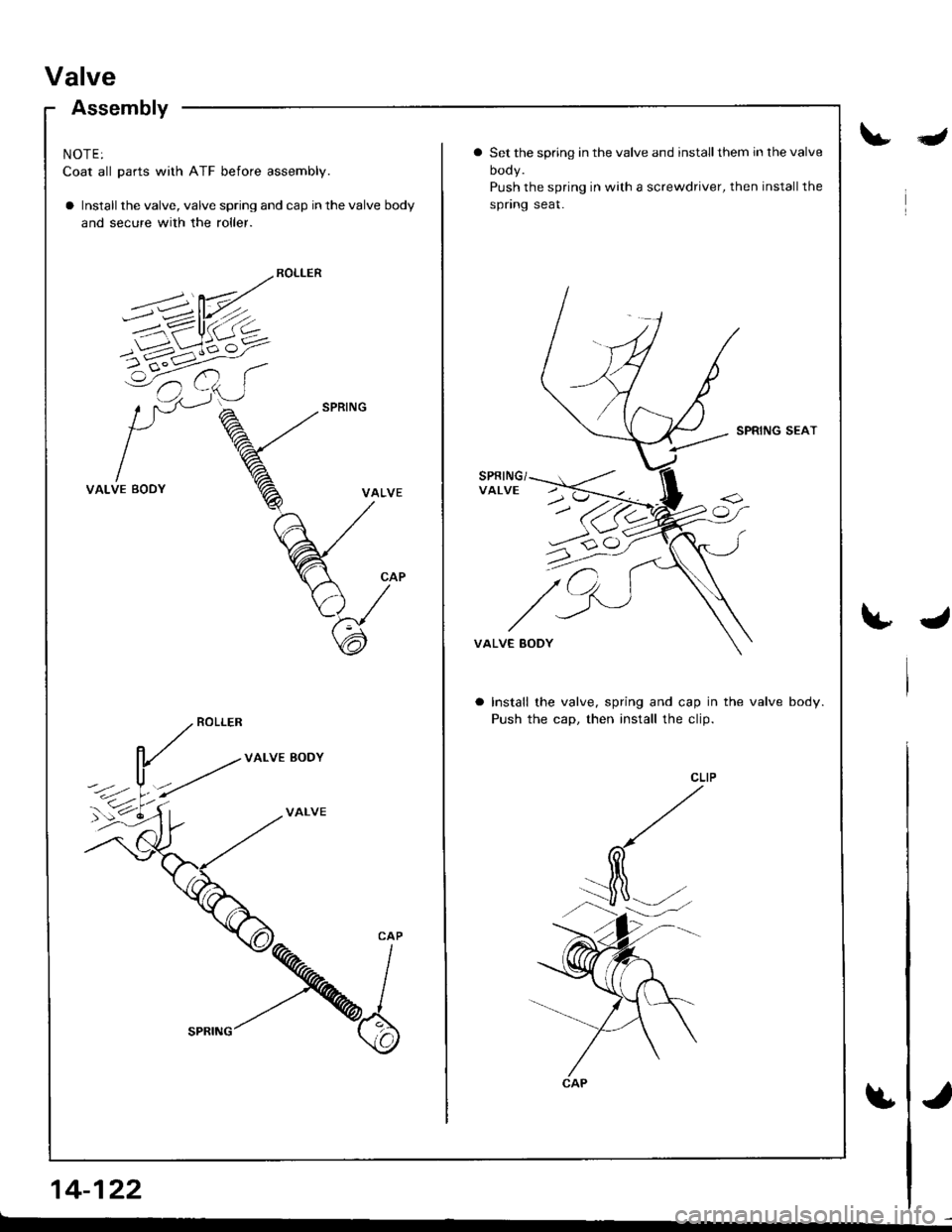
NOTE:
Coat all parts with ATF before assembly.
a Install the valve, valve spring and cap in the valve body
and secure with the roller.
VALVE BODY
VALVE
14-122
Ia Set the spring in the valve and installthem in the valve
oooy.
Push the spring in with a screwdriver, then installthe
spnng seat.
SPRING SEAT
VALVE EODY
Install the valve, spring and cap in the valve body.
Push the cap, then install the clip.
Page 584 of 1681
Transmission
lnstallation
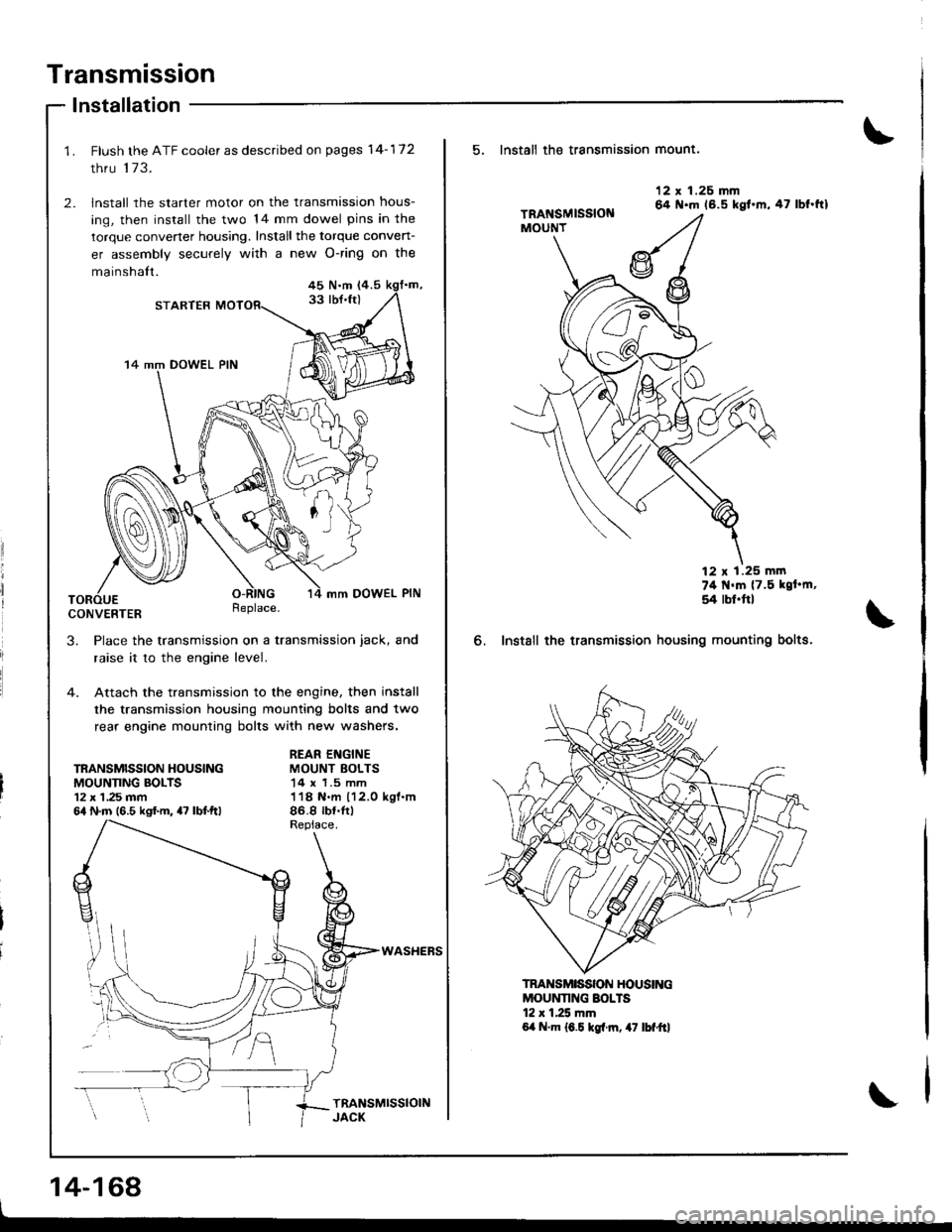
Flush the ATF cooler as described on pages 14-172
thru 173.
lnstall the starter motor on the transmission hous-
ing, then install the two 14 mm dowel pins in the
torque convener housing. Install the torque conven-
er assembly securely with a new O-ring on the
mainshalt.45 N.m (4.5
33 lbJ.ft)STARTER
14 mm DOWEL PIN
mm DOWEL PIN
CONVERTERReplace.
3. Place the transmission on a transmission jack, and
raise it to the engine level.
4. Attach the transmission to the engine, then install
the transmission housing mounting bolts and two
rear engine mounting bolts with new washers.
TRANSMISSION HOUSINGMOUNNNG BOLTS12 x 1 ,25 mm64 N.m (6.5 kgf.m, 47 lbf.ftl
REAR ENGINEMOUNT BOLTS14 x 1.5 mm118 N.m 112.0 kgl.m86.8 rb{.tr)
WASHEFS
14-168
5. Install th€ transmission mount.
6. Instsll the transmission
12 x 1.26 mm64 N.m 16.5 kgt.m,47 lbf.ftl
74 t{'m {7.5 kgt'm,
54 rbl.ftl
housing mounting bolts.
MOUNNNG SOLTS12 r 1.25 mm6,t N.m 16.5 kgl.rn, 47 lbf"ftl
TRANSMISSON HOUSING
Page 588 of 1681
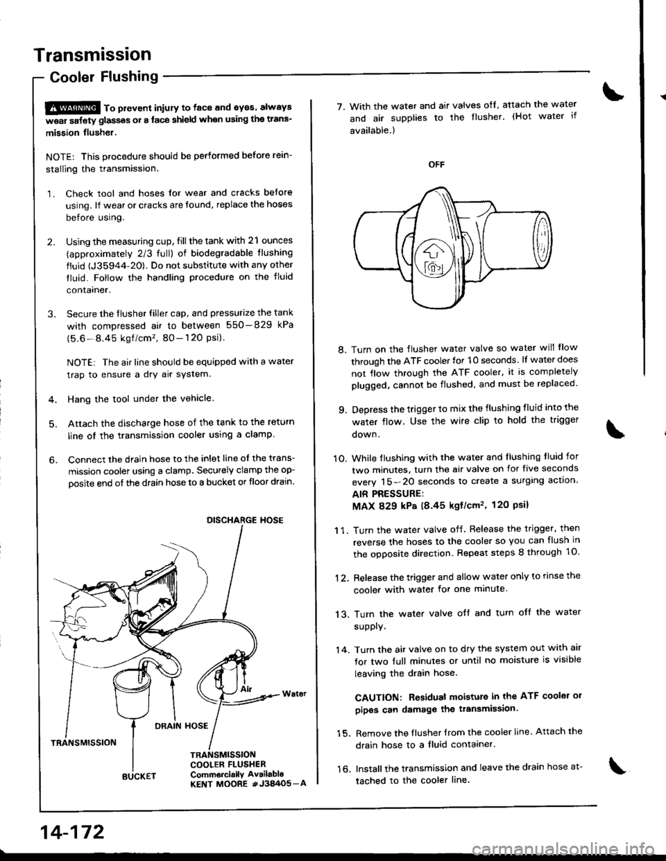
Transmission
Cooler Flushing
S@ to pttvont iniury to face and syes' always
w6ar safety glassos or a face shield when using the trans-
mission flusher.
NOTE: This procedure should be performed before rein-
stalling the transmission.
1. Check tool and hoses for wear and cracks before
using. lf wear or cracks are found, replace the hoses
before using.
2. Using the measuring cup, fill the tank with 21 ounces
(approximately 2/3 full) of biodegradable tlushing
fluid {J35944-20). Do not substitute with any orher
tluid. Follow the handling procedure on the tluid
contalner.
3. Secure the flusher filler cap, and pressurize the tank
with compressed air to between 550-829 kPa
{5.6-8.45 kgf /cm'�, 80- 120 Psi}.
NOTE: The air line should be equipped with a water
trap to ensure a dry air system.
4. Hang the tool under the vehicle
5. Attach the discharge hose of the tank to the return
line oI the transmission cooler using a clamp
6. Connect the drain hose to the inlet line of the trans-
mission coolel using a clamp. Securely clamp the op-
oosite end of the drain hose to a bucket or tloor drain.
DRAIN HOSE
TRANSMISSION
TRANSMISSIONCOOLER FLUSHERComm6rci.llY Av.ilabloKENT MOORE #J3A/O5_A
DISCHARGE HOSE
14-172
BUCKET
7. With the water and air valves ofl, atach the water
and air supplies to the flusher. (Hot water if
available.)
8. Turn on the flusher water valve so water will flow
through the ATF cooler for 10 seconds. lf water does
not flow through the ATF cooler, it is completely
plugged, cannot be flushed, and must be replaced
9. Depress the trigger to mix the flushing fluid into the
water flow. Use the wire clip to hold the trigger
oown.
1O. While tlushing with the water and llushing f luid for
two minutes. turn the air valve on for five seconds
everv 15-20 seconds to create a surglng actlon.
AIR PRESSURE:
MAX 829 kP8 18.45 kgf/cm'�, 120 Psil
1 1. Turn the water valve off. Release the trigger. then
reverse the hoses to the cooler so you can flush in
the ooDosite direction. Repeat steps 8 through 1O.
12, Release the trigger and allow water only to rinse the
cooler with water for one minute.
13. Turn the water valve oJf and turn off the water
supply.
'14. Turn the air valve on to dry the system out with air
for two full minutes or until no moisture is visible
leaving the drain hose.
CAUTION: Residual moisture in the ATF coolei 01
pipos can damage the transmission.
15. Remove the flusher {rom the cooler line. Attach the
drain hose to a fluid contaaner.
16. Installthe transmission and leave the drain hose a1-
tached to the cooler line.
Page 589 of 1681
![HONDA INTEGRA 1998 4.G Owners Manual 17. Make sure the transmission is in E] position.
Fill the transmission with ATF, and run the engineJor 30 seconds or until approximately one quart isdischarged.
18. Remove the drain hose, and reconn HONDA INTEGRA 1998 4.G Owners Manual 17. Make sure the transmission is in E] position.
Fill the transmission with ATF, and run the engineJor 30 seconds or until approximately one quart isdischarged.
18. Remove the drain hose, and reconn](/img/13/6069/w960_6069-588.png)
17. Make sure the transmission is in E] position.
Fill the transmission with ATF, and run the engineJor 30 seconds or until approximately one quart isdischarged.
'18. Remove the drain hose, and reconnect the coolerreturn hose to the transmission.
19. Refillthe tiansmission with ATF to the propef level.
FILLER CAP
TOOL MAINTENANCE
1. Empty and rinse after each use. Fill the can withwater and pressurize the can. Flush the dischargeline to ensure that the unit is clean.
2. lf discharge liquid does not foam, the orifice may beblocked.
3, To clean, disconnect the plumbing from the tank atthe large coupling nut,
4. Remove the in-line filter trom the discharge side andclean if necessary.
5. The fluid oritice is located behind the filter.
Clean it with the pick stored in the bottom of the tankhandle or blow it clean with air. Securely reassem-
ble all parts.
COUPLING NUT
FILTER
\
IO-RINGORIFICE
14-173