ECU HONDA INTEGRA 1998 4.G Repair Manual
[x] Cancel search | Manufacturer: HONDA, Model Year: 1998, Model line: INTEGRA, Model: HONDA INTEGRA 1998 4.GPages: 1681, PDF Size: 54.22 MB
Page 940 of 1681
Child Seat Anchor Plate
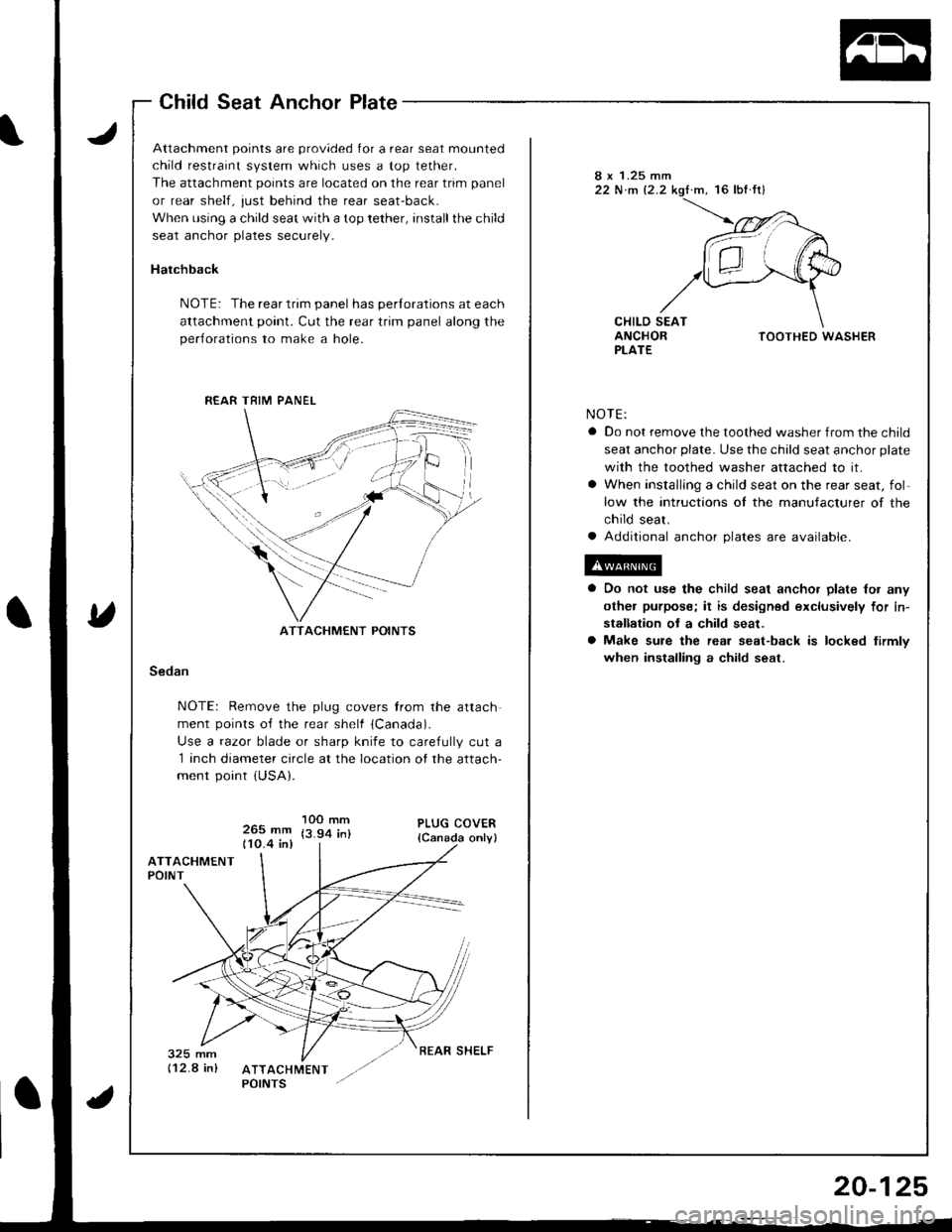
Attachment points are provided for a rear seat mounted
child restraint system which uses a top tether.
The attachment points are located on the rear trim panel
or rear shelf, just behind the rear seat-back.
When using a child seat with a top tether, installthe child
seat anchor plates securely.
Hatchback
NOTE: The rear trim panel has perlorations at each
attachment point. Cut the rear trim panel along the
perlorations to make a hole.
8 x 1.25 mm22 N.m 12.2.m, 16 lbf fr)
CHILD SEATANCHORPLATETOOTHED WASHER
NOTE:
a Do not remove the toothed washer from the child
seat anchor plate. Use the child seat anchor plate
with the toothed washer attached to it.
a When installlng a child seat on the rear seat, fol-
low the intructions ol the manufacturer of the
child seat.
a Additional anchor plates are available.
Do not use the child seat ancho. plate lor any
othel purpose; it is designed exclusively for in-
stallation ot a child seat.
Make sure the rear seat-back is locked tirmlv
when installing a child seat.Sedan
NOTE: Remove the plug covers trom the attach
ment points o{f the rear shelf {Canada).
Use a razor blade or sharp knife to carefully cut a
1 inch diameter circle at the location of the attach-
ment point {USA}.
265 mm110.4 in)
1OO mm(3.94 in)
R€AR TRIM PANEL
ATTACHMENT POINTS
REAR SHELF
Page 944 of 1681
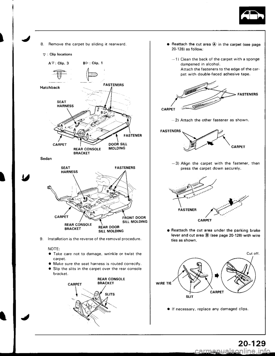
I8. Remove the carpet by sliding it rearward.
V : Clip locations
AV : Clip, 3BD : Clip. 1
A"= l
"
Hatchback
CARPET
Sedan
SEATHARNESS
FASTENERS
FASTENER
DOOR SILL
FASTENERS
oooRSILL MOLDING
SEATHARNESS
I
CARPET
REAR CONSOLEBRACKET
Installation is the reverse oJ the removal procedure.
NOTE:
a Take care not to damage, wrinkle or twist the
carpet.
a Make sure the seat harness is routed correctly.
a Slip the slits in the carpet over the rear console
bracket.
REAR CONSOLEBBACKETP
REAR DOORSILL MOLDING
9.
CAR
a Reattach the cut area @ in the carpet (see page
20-128) as follow.'
- 1) Clean the back of the carpet with a sponge
dampened in alcohol.
Attach the fasteners to the edge ol the car-
pet with double laced adhesive tape.
FASTENERS
CARPET
3) Align the carpet with the fastener,
press the carpet down securely.
then
CARPET
a Reattach the cut area under the parking brake
lever and cut area @ (see page 20-128) with wire
ties as shown.
WIRE TIE
Cut otl.
a lf necessary, replace any damaged clips.
2) Attach the other lastener as shown.
FASTENER
SLIT
20-129
Page 960 of 1681
Il
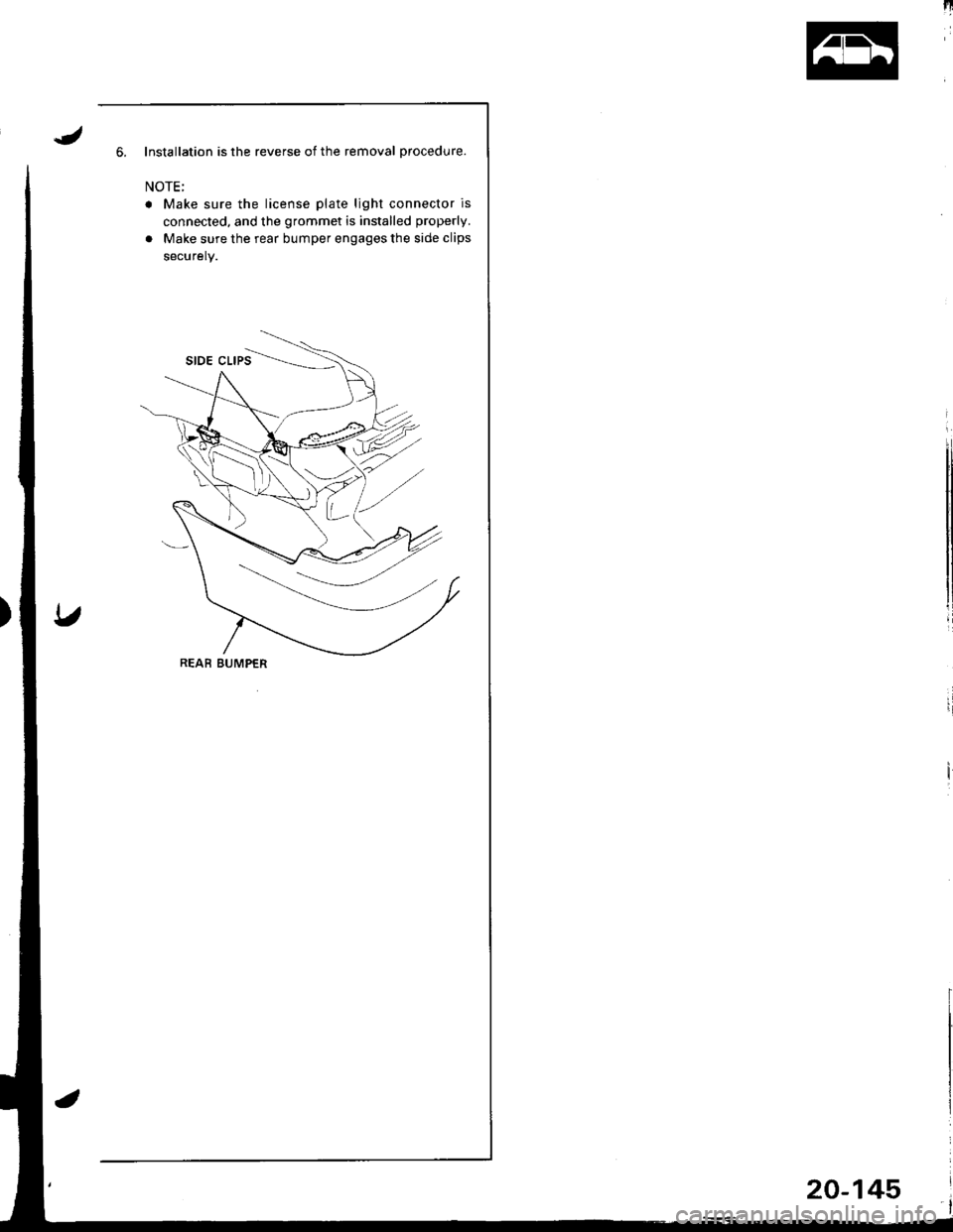
6. Installation is the reverse of the removal procedure.
NOTE;
r Make sure the license plate light connector is
connected, and the grommet is installed properly.
. Make sure the rear bumper engages the side clips
securely.
REAB BUMPER
20-145
Page 961 of 1681
Hood
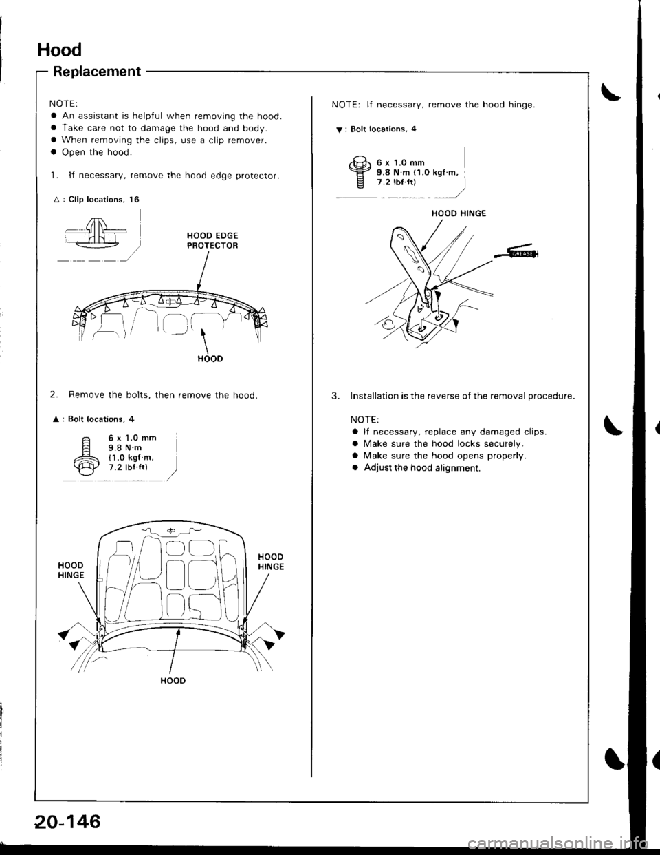
Replacement
NOTE:
a An assistant is helplul when removing the hood.
a Take care not to damage the hood and body.
a When removing the clips, use a clip remover.
a Open the hood.
'L IJ necessary, remove the hood edge protector.
A : Clip locations, l6
NOTE: lf necessary, remove the hood hinge.
V: Bolt locations, 4
,G,, 6 r t.o -,n\Yz s e N.- {1.o kot.m.E z.z rur.rtr - i
2. Remove the bolts, then remove the hood.
i Bolt locations, 4
3.Installation is the reverse of the removal procedure.
NOTE:
a lf necessary, replace any damaged clips.
a Make sure the hood locks securely.
a Make sure the hood opens properly.
a Adjust the hood alignment.
6 x 1.O mm9.8 N.m{1.0 kgl m,7.2 tbf ft)
HOOD IIINGE
HOOD
!
D
HOOD
Page 962 of 1681
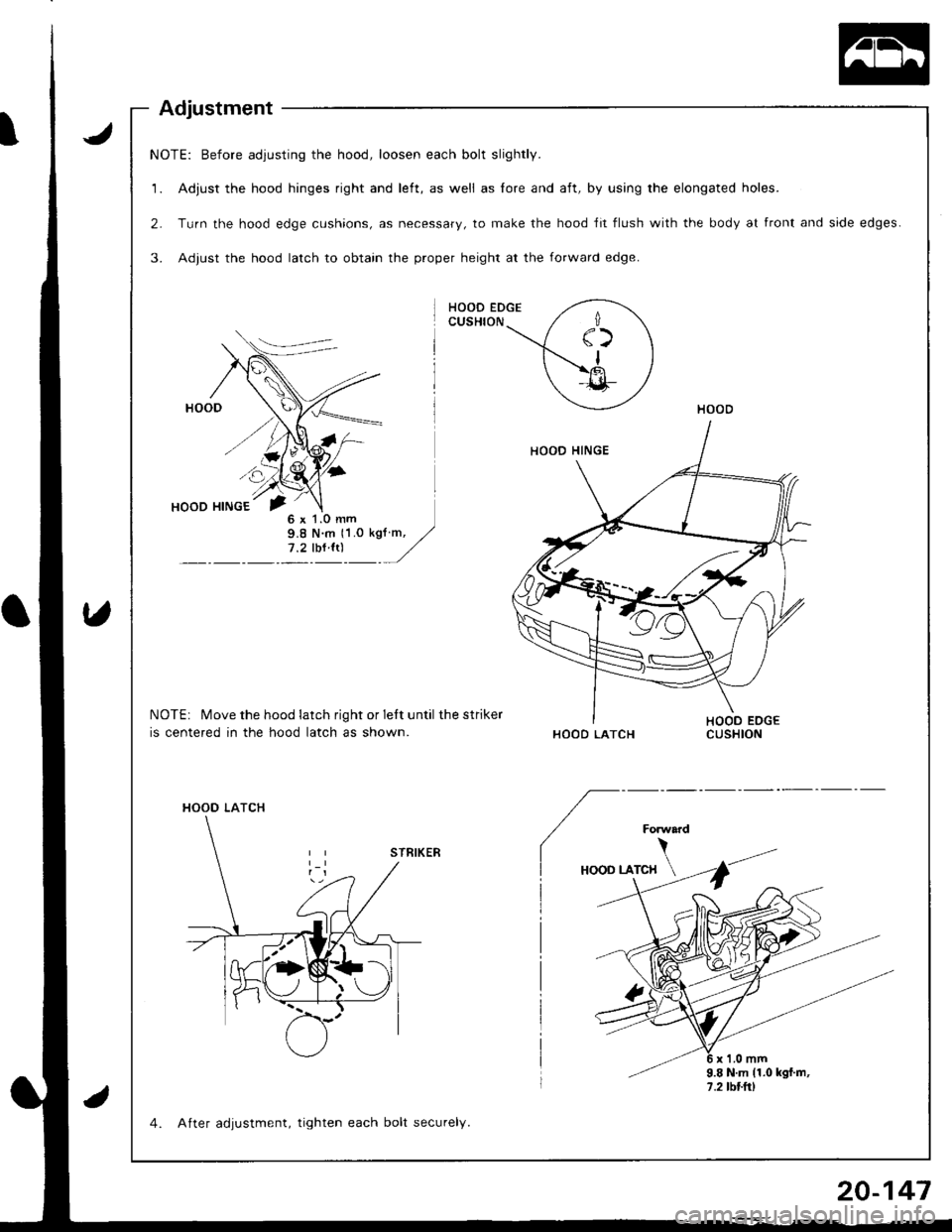
NOTE: Before adjusting the hood, loosen each bolt slightly.
1. Adjust the hood hinges right and left, as well as lore and aft, by using the elongated holes.
2. Turn the hood edge cushions, as necessary, to make the hood ,fit flush with the body at front and side edges.
3. Adjust the hood latch to obtain the proper height at the forward edge.
HOOD EDGECUSHION
NOTEi Move the hood latch right or lett until the striker
is centered in the hood latch as shown.HOOD LATCH
HOOO LATCH
7.2lblltl
4. After adjustment, tighten each bolt securely.
Page 964 of 1681
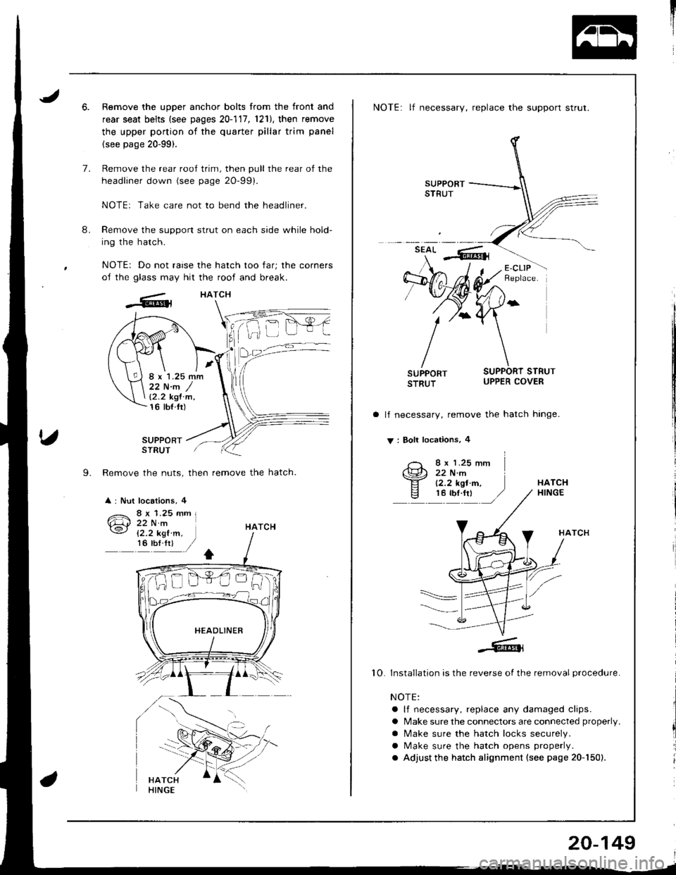
6.Remove the upper anchor bolts from the front and
rear seat belts (see pages 20-111,1211, then remove
the upper portion of the quarter pillar trim panel
(see page 20-99).
Remove the rear roof trim, then pull the rear of the
headliner down (see page 2O-99).
NOTE: Take care not to bend the headliner.
Remove the support strut on each side while hold-
ing the hatch.
NOTE: Do not raise the hatch too far; the corners
of the glass may hit the roof and break.
HATCH
8.
7.
SUPPORTSTRUT
L Remove the nuts, then remove the hatch.
: Nut locations, 4
22 N.m /12.2 kgl'm,16 tbt.fr)
HATCH
NOTE: lf necessary, replace the support strut.
lf necessary, remove the hatch hinge.
V : Boll locations, 4
I x 1.25 mm22 N.m(2.2 kgl.m,HATCH
10
HATCH
Installation is the reverse of the removal procedure.
NOTE:
a lf necessary, replace any damaged clips.
a Make sure the connectors are connected properly.
a N4ake sure the hatch locks securely.
a Make sure the hatch opens properly.
. Adjust the hatch alignment (see page 20-150).
20-149
Page 965 of 1681
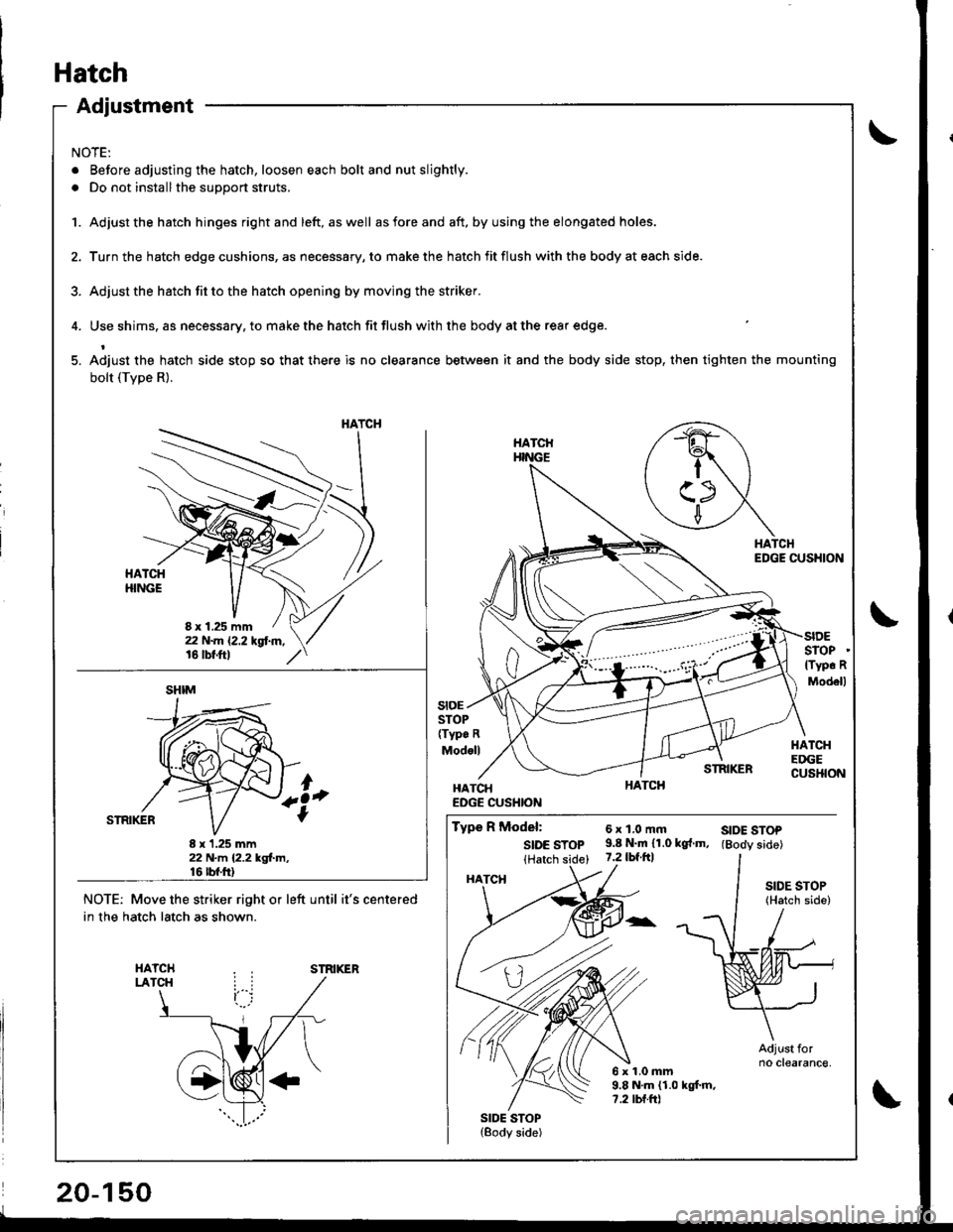
Adjustment
NOTE:
. Before adjusting the hatch, loosen each bolt and nut slightly.
. Do not installthe support struts.
1. Adjust the hatch hinges rightand left, aswell asforeand aft. byusing the elongated holes.
2. Turn the hatch edge cushions, as necessary, to make the hatch fit flush with the body at each side.
3. Adjust the hstch fit to the hatch opening by moving the striker.
4. Use shims. as necessary, to make the hatch fit flush with the body at the rear edge.
5. Adiust the hatch side stop so that there is no clearance between it and the body side stop, then tighten the mounting
bolt (Tvpe R).
HATCHEDGE CUSHION
STOP(Typ. R
Modoll
SIDESTOPlTyp. R
Modell
HATCHEDGECUSHION
stoE
STRIKER
HATCHEDGE CUSHION
Type R Model:
SIDE STOP(Hatch side)
SIDE STOP(Body side)
6xl,0mft9.8 N.m 11.0 kg{.m,7.2 tbf.ftl
6x1.0mm9.8 N.m (1.0 kgt m,?.2 tbf.ftl
SIDE STOP(Hatch side)
Adjust forno clearance,
SIDE STOP(Body side)
NOTE: Move the striker right or left until it's centered
in the hatch latch as shown.
STRIKER
HATCH
8 x 1.25 mm
SHIM
8 x 1.25 mm22 N.m 12.2 kgl.m,16 rbt.ft)
HATCH
Page 967 of 1681
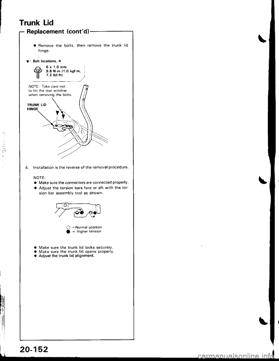
Trunk Lid
Replacement (cont'dl
i
I
a Remove the bolts, then remove the trunk
nrnge.
V: Bolt locations, 4
tid
6x 1.0 mm9.8 N m {'1.0 kgt m,7.2 lbr'ftl
)
NOTE: Take care notto hit the rear wrndowwhen removing the bolts.
4. Installation is the reverse o{ the removal procedure.
NOTE:
a Make sure the connectors are connected properly.
a Adjust the torsion bars lore or aft with the tor
sion bar assembly tool as shown.
O =Normal PositionO = Higher tension
a Make sure the trunk lid locks securely.a Make sure the trunk lid opens properlv.a Adiust the trunk lid alignment.
Page 968 of 1681
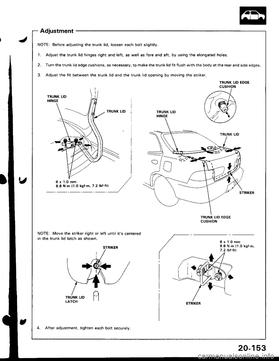
NOTE: Before adjusting the trunk lid. loosen each bolt slightly.
1. Adjust the trunk lid hinges right and left, as well as fore and att, by using the elongated holes.
2. Turn the trunk lid edge cushions, as necessary. to make the trunk lid fit flush with the body at the rear and side edges.
3. Adjust the lit between the trunk lid and the trunk lid opening by moving the striker.
TNUNK LID EDGECUSHION
TRUNK LIOHINGE
NOTE: Move the striker right or left until it's centered
in the trunk lid latch as shown.6 r 1.0 mm9.8 N m (1.O kgf .m,
7 .2 tbt.ltl
6 x '1.0 mm
STRIKER
STFIKER
4. After adjustment, tighten each bolt securely.
Adjustment
20-153
Page 971 of 1681
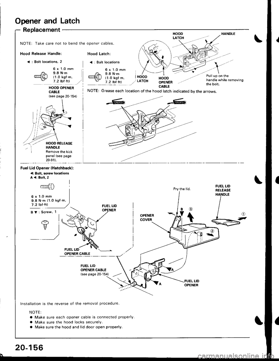
Opener and Latch
Replacement
Hood Release Handle:
< : Bolt locations, 2
HANDLE
NOTE: Take care not to bend the opener cables.
Hood Latch:
< | Bolt locations
6 x 1.0 mm9.8 N.m(1 .0 kgf m,7 .2 thl ltlHOODOPENERCAELE
Pull up on thehandle while removingthe bolt.HOOD OPENERCABLE(see page 20-154)
NOTE: Grease each location ofthe hood latch indicated bvthe arrows.
Pry the lid.
OPENERCOVER
Remove the kickpanel (see page20-9r ).
Fuel Lid Opener {Hstchbackl:
<: Bolt. screw locdionsA <: Boh.2
6x1.0mm9.8 N m 11.0 kgf m,
7 .2 lbl lrl
BV: Screw, 1
FUEL LIDRELEASEHANDLE
@
Ib
t
lnstallation is the reverse of the removal procedure.
NOTE:
a Make sure each opener cable is connected properly.
a Make sure the hood locks securely.
a Make sure the hood and lid door open properly.
FUEL LIDOPENER CAELE(see page 20-154)
20-156