heater HONDA INTEGRA 1998 4.G Owner's Manual
[x] Cancel search | Manufacturer: HONDA, Model Year: 1998, Model line: INTEGRA, Model: HONDA INTEGRA 1998 4.GPages: 1681, PDF Size: 54.22 MB
Page 950 of 1681
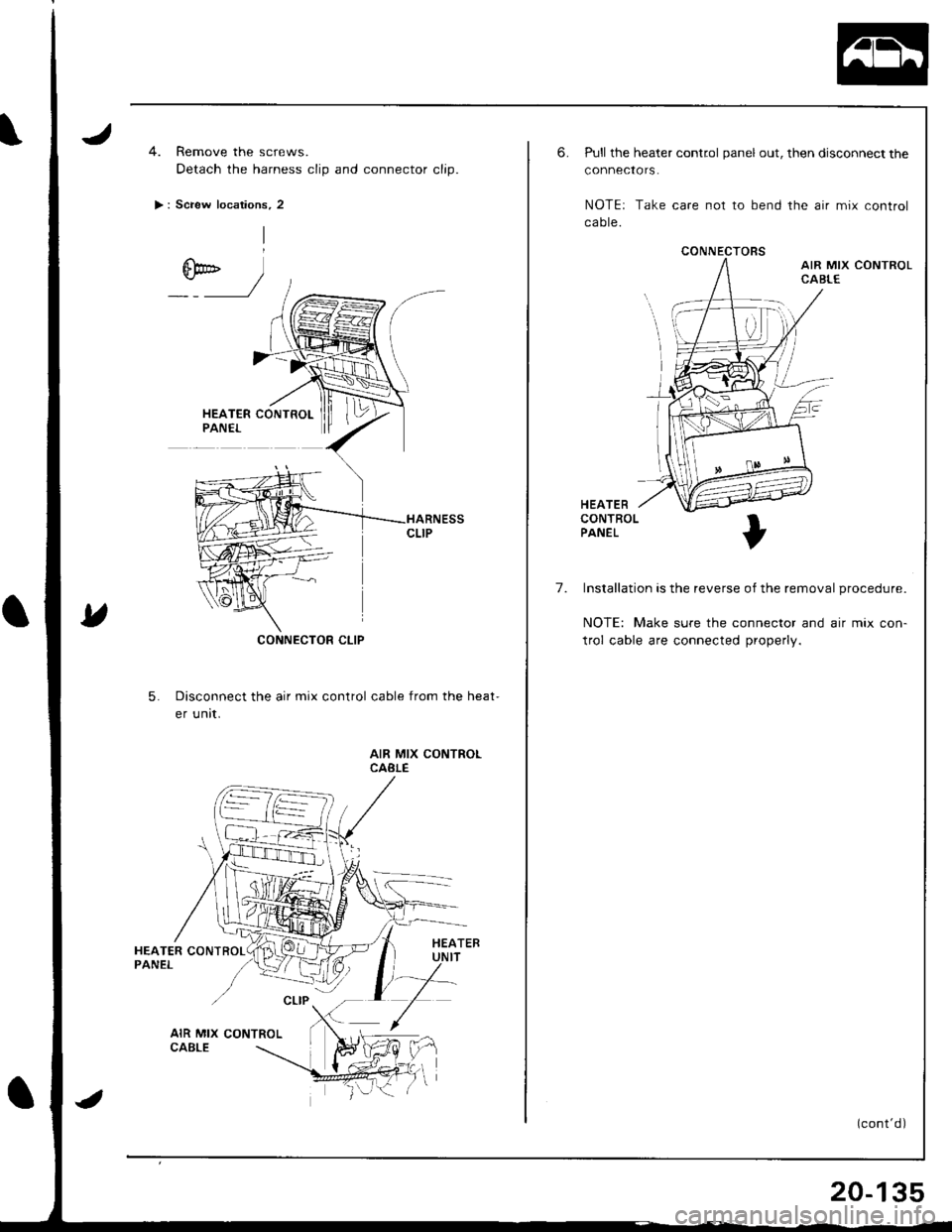
4. Remove the screws.
Detach the harness clip and connector clip.
> : Screw locations, 2
CONNECTOR CLIP
5.Disconnect the air mix control cable from the heat-
er unit.
AIR MIX CONTROLCABLE
CONNECTORS
6.Pull the heater control panel out, then disconnect the
connectors.
NOTEr Take care not to bend the air mix control
ca ote.
HEATERCONTROLPANEL
7. Installation is the reverse of the removal procedure.
NOTE: Make sure the connector and air mix con-
trol cable are connected properly.
(cont'd)
20-135
Page 954 of 1681
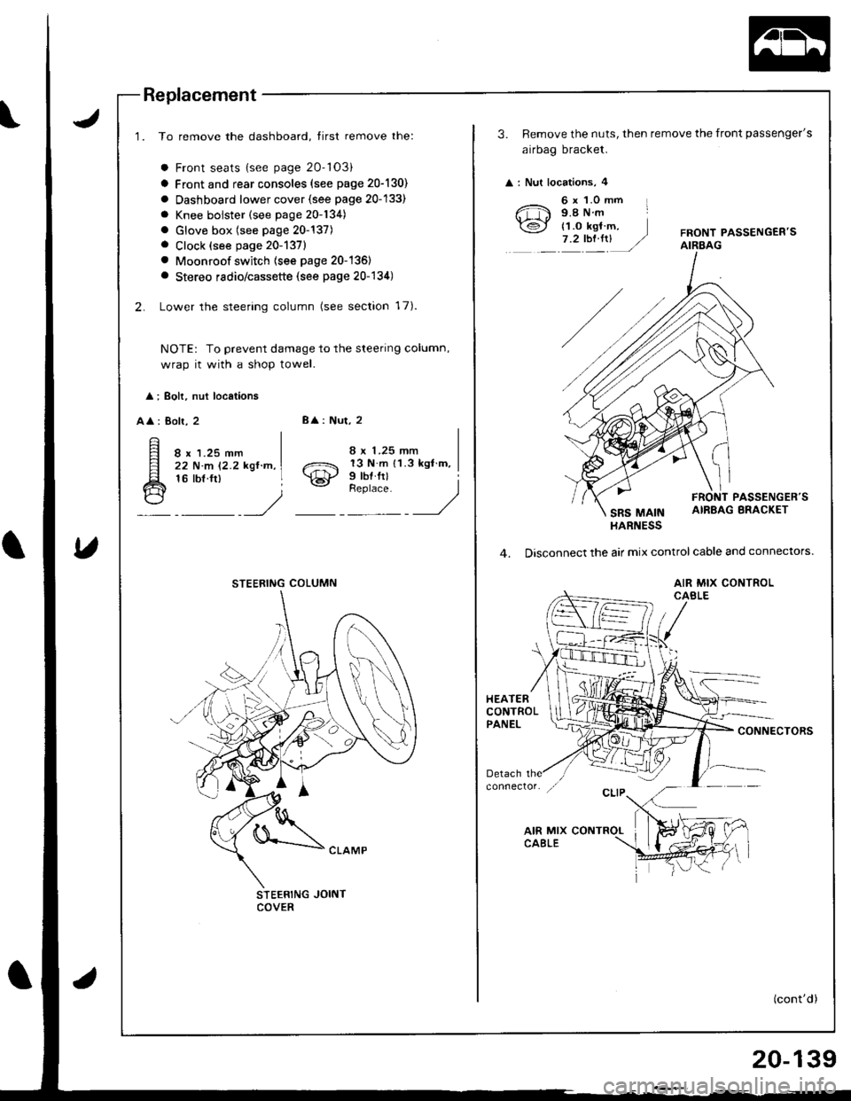
Replacement
1. To remove the dashboard, tirst remove the:
a Front seats {see page 20-'103)
a Front and rear consoles (see page 20-130)
a Oashboard lower cover {see page 20-133)
a Knee bolster (see page 20-134)
. Glove box (see page 20-137). Clock (see page 20-1371
. Moonroof switch (see page 20-136)
a Stereo radio/cassette (see page 20-134)
2. Lower the steering column (see section 17).
NOTE: To prevent damage to the steering column,
wrap it with a shop towel.
l ; Boh, nut locations
AA : Bolr, 28
: Nut, 2
8 x 1.25 mm22 N.m 12.2 kgl.n,16 tbf.ft)o21 13 N m 11.3 kgl m,
\€J' Prbl rll
_Urr'rr,t __)
STEERING JOINTCOVER
STEERING COLUMN
3. Remove the nuts, then remove the front passenger's
airbag bracket.
: Nut locations, 4
6 x 1.0 mm L9.8Nm
{1.o kgt m,7.2tbt.rrUFRONT PASSENGEB'SAIRBAG
PASSENGER'S
SRS MAINAIRBAG BRACKET
HARNESS
4. Disconnect the air mix control cable and connectors.
AIR MIX CONTROLCABLE
HEATERCONTROLPANELCONNECTORS
(cont'd)
20-139
Page 988 of 1681
iii
i
I
J
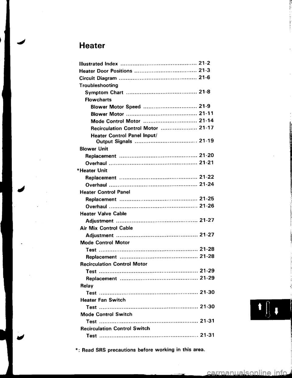
Heater
fffustrated Index ............. ......'..21-2
Heater Door Positions '....'........ 21-3
Circuit Diagram ....................... 21-6
Troubleshooting
Symptom Chart ............. '.....21-8
Flowcharts
Blower Motor Speed ...............'......'........ 21 -9
Blower Motor ............'......21-11
Mode Controf Motor ............ ............'... "' 21 -14
Recirculation Control Motor ......'...... "'.,.,. 21 -1 7
Heater Control Panel Input/
Output Signals ...'.......... 21-19
Blower Unit
Replacement ........ '....... ',..,.. 21-2O
Overhaul ",',..21-21
*Heater Unit
Repf acement .....'.....'........'.. 21'22
Overhaul .......21-24
Heater Control Panel
Repfacement ....... '..... '......... 21-25
Overhaul .......21-26
Heater Valve Cable
Adjustment '.. 21'27
Air Mix Control Cable
Adiustment ... 21-27
Mode Control Motor
Test .............. ..................... 21'24
Repfacement ....................... 21-24
Recirculation Control Motor
Test .............. ..................... 21-29
Repf acement .........'........ " ". 21-29
Relay
Test .............. ..................... 21-3O
Heater Fan Switch
Test .............. ....................' 21-30
Mode Control Switch
Test .............' "'..............'... 21-31
Recirculation Control Switch
Test .............. ..................... 21-31
*: Read SRS precautions before working in this area.
Page 989 of 1681
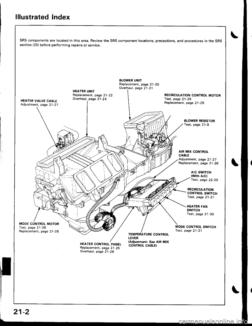
lllustrated Index
SRS components are located in this area. Review the SRS component locations. precautions, and procedures in the SRSsection (23) before performing repairs or service.
BLOWER UNITReplacement, page 21-2OOverhaul, page 21.21
HEATER VALVE CABLEAdiustment, page 21-27
HEATER UNITReplacement, page 21-22Overhaul, page 21-24RECIRCULATION CONTROL MOTORIest, page 21,29Seplacement, page 21-29
BLOWER RESISTORTest, page 21-9
AIR MIX CONTROLCABLEAdjustment, page 21-27Replacement, page 21-26
A/C SWTTCH{with A/clTest, page 22-20
RECIRCULATIONCONTROL SWITCHTest, page 21,31
HEATER FANswrTcHTest, page 21-30
MODE CONTROL MOTORTest, page 21-28Replacement, page 2 l -28CONTROL SWITCHTest, page 21-3'l
HEATER CONTROL PANELReplacement, page 21,25Overhaul, page 21-26
TEMPERATURE CONTROLLEVERlAdjustment: Soe AIR MIXCONTROL CABLEI
21-2
Page 990 of 1681
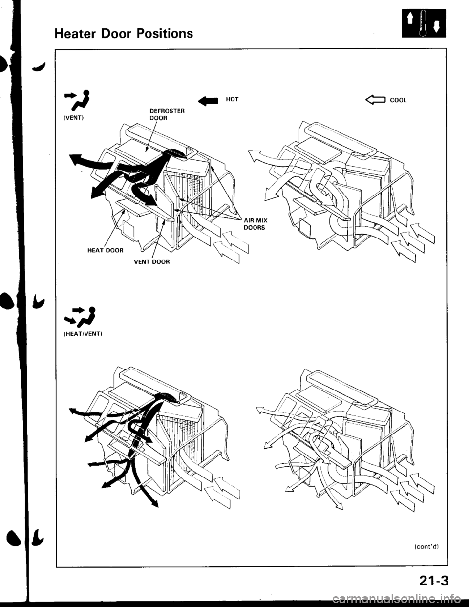
Heater Door Positions
II Horfr coor
r>O
t
IHEAT/VENTI
(cont'd)
VENT DOOR
21-3
Page 991 of 1681
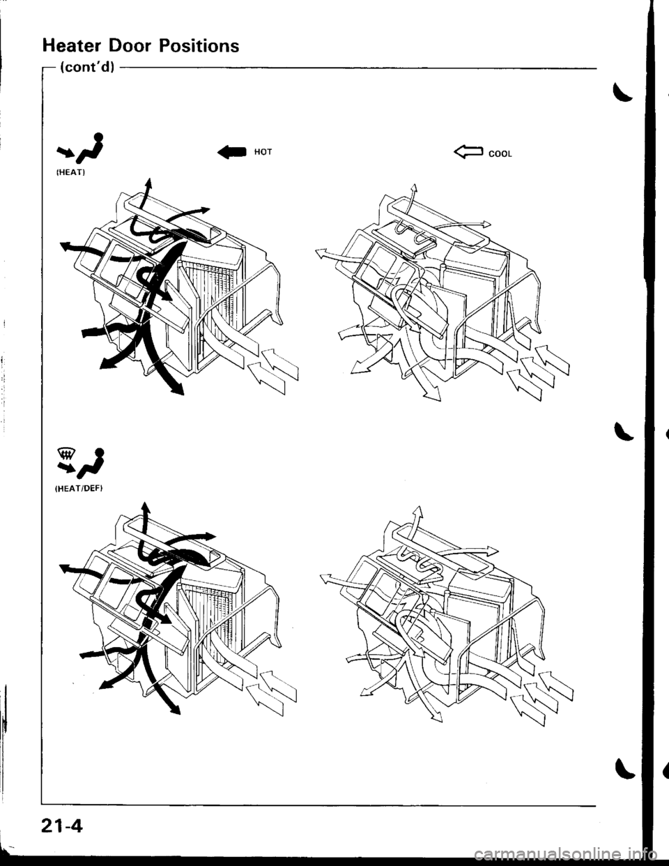
Heater Door Positions
(cont'd)
fr seel
21-4
Page 995 of 1681
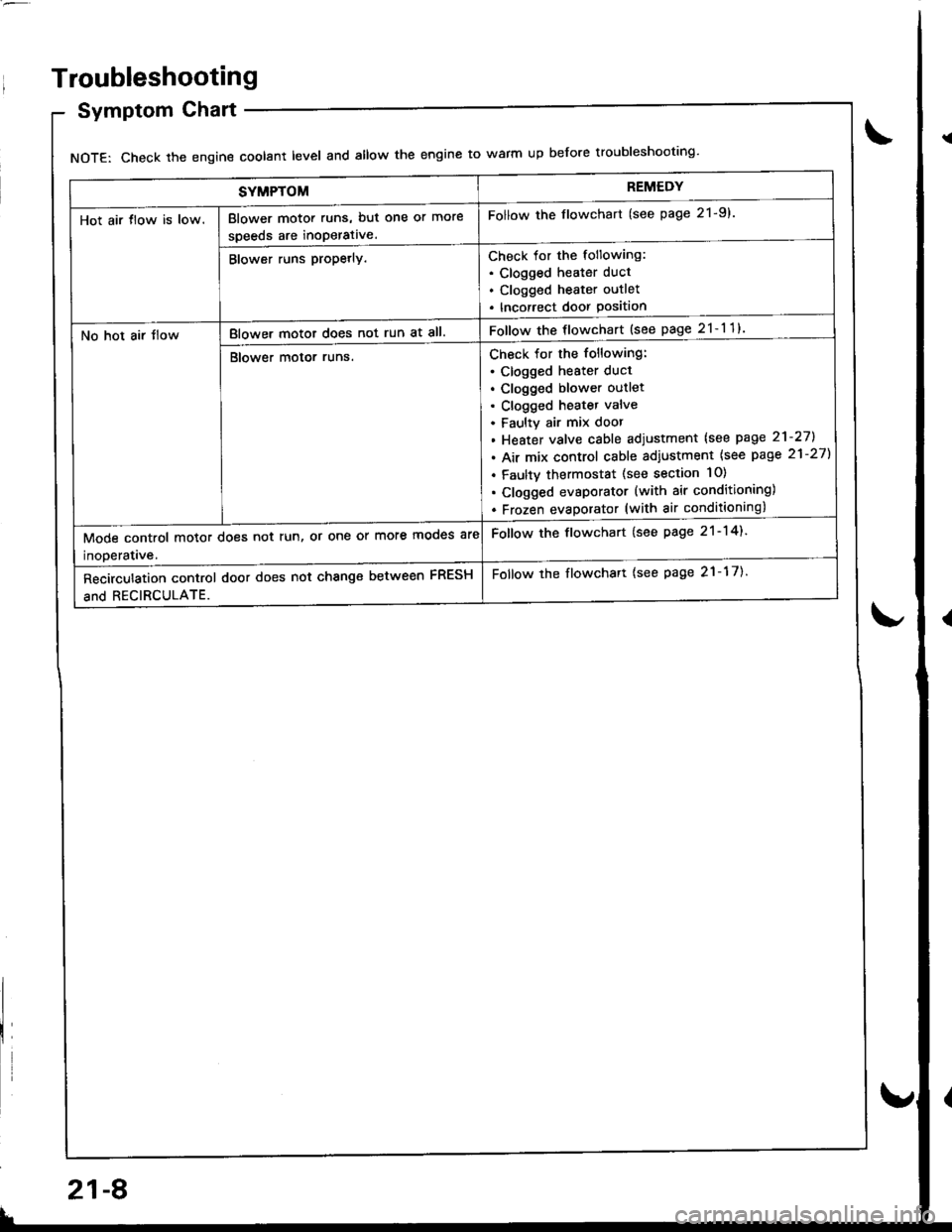
SYMPTOMREMEDY
Hot air tlow is low.Blower motor runs, but one or more
speeds are inoperative.
Follow the flowchart (see page 21-9).
Blower runs propetly.Check for the following:. Clogged heater duct
. Clogged heater outlet
. Incorrect door Position
No hot air tlowBlower motor does not run at all.Follow the flowchart {see page 21-11}
Blower motor runs.Check for the following:
. clogged heater duct
. Clogged blower outlet. Clogged heatet valve
. Faultv air mix door
. Heater valve cable adjustment lsee page 21-27].
. Air mix control cable adiustment {see page 21-27)
. Faulty thermostat (see section 10)
. Clogged evsporator (with air conditioning)
. Frozen evaDorator (with air conditioning)
Mode control motor does not run, or one or more mooes are
inoDeratave.
Follow the flowchart (see page 21-14).
Recirculation control door does not change between FRESH
and RECIRCULATE.
Follow the flowchart {see page 21-17).
Troubleshooting
Symptom Chart
NOTE: Check the engin€ coolant level and allow the engine to warm up before troubleshooting'
21-8
v
Page 996 of 1681
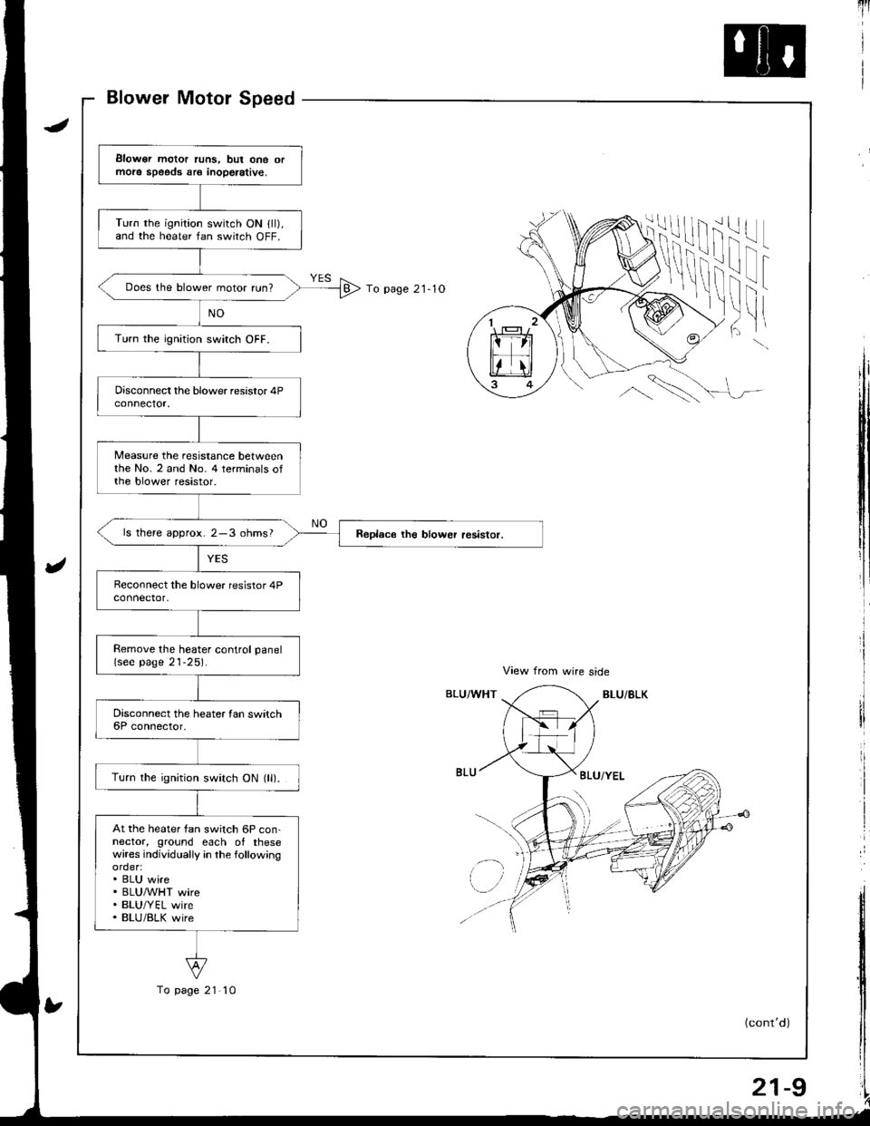
qrt
View from wire side
BLU/BLKBLU/WHT
1
To page 21- 1O
ii!
i'l! |
f
'tr
t
!
I
!I
tl
\\
BLU/YEL
l'r
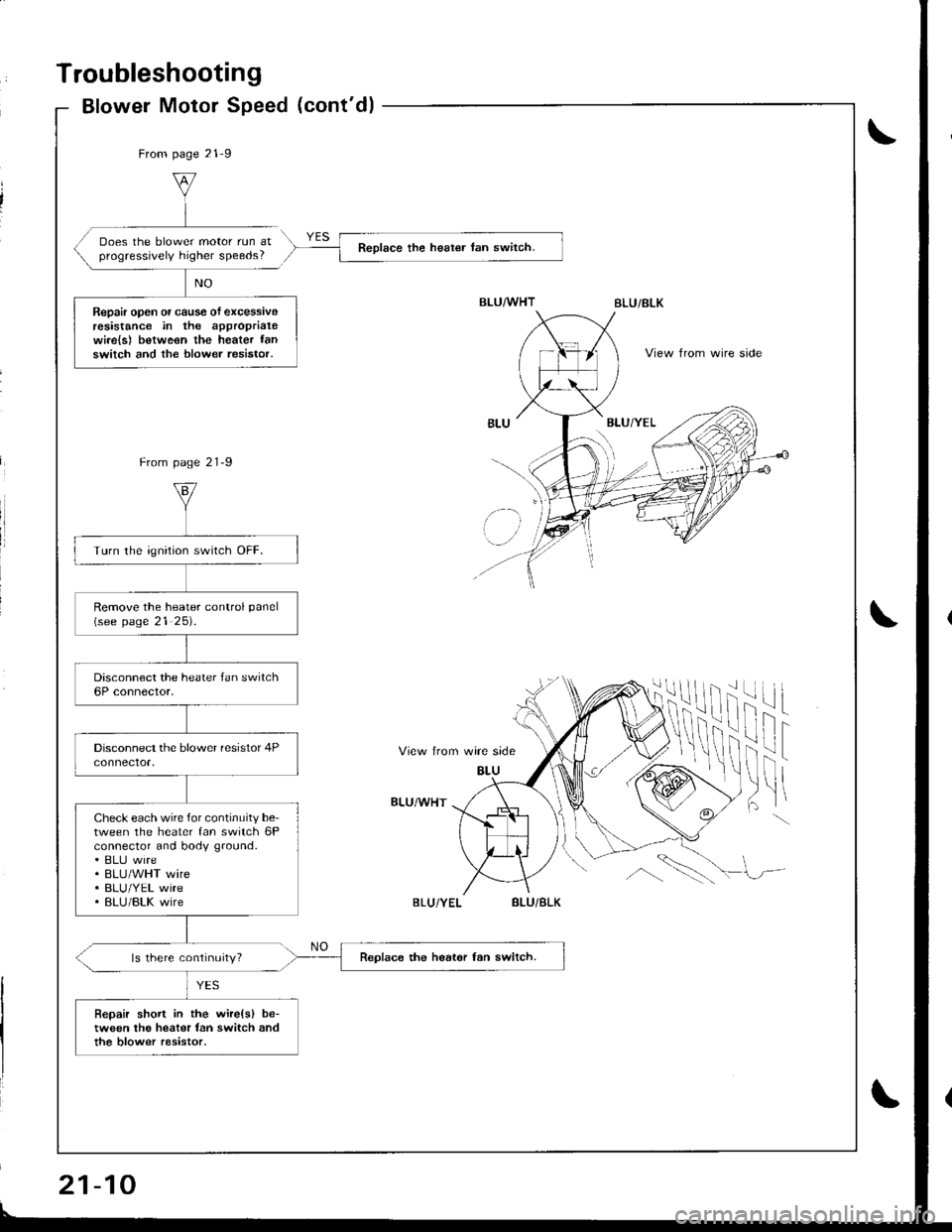
Elowor motor runs, but one ormole speeds sr€ inoperative,
Turn the ignition switch ON lll),and the heater fan switch OFF.
Does the blower motor run?
Turn the ignition switch OFF.
Measure the resistance betweenthe No. 2 and No. 4 terminals ofthe blower resistor.
ls there approx. 2-3 ohms?
Remove the heater control panel(see page 21-25).
Turn the ignition switch ON (ll).
At the heater fan switch 6P con-nector, ground each of thesewires individually in the followingorder:. BLU wire. BLUMHT wire. BLU/YEL wire. BLU/BLK wire
To page 21 10
(cont'd)
21-9
Page 997 of 1681
Troubleshooting
Blower Motor Speed (cont'dl
From page 21-9
Does the blower motor run atprogressively higher speeds?Reolace the heat€r tan switch.
Repair open or cause of excessiveresistance in the approprialewi.e{s) betweon the heater fanswitch and the blower resistor.View from wire side
From page 21-9
View trom wire side
BLU
ilif
fril t
)ltBLU/WHT
ls there continuity?
BLU/BLK
BLU
' lz-
Turn the ignition switch OFF.
Remove the heater conlrol panel(see page 21 25).
Check each wire for continuity be-tween the heater fan switch 6Pconnector and body ground.. ELIJ wire. BLU/WHT wire. BLU/YEL wire. BLU/BLK wire
Replace the heat6r fan switch.
Bepair short in the wire(sl be-tween the heater fan switch andthe blow€r resistor.
If
\!,\
BLU/BLK
21-10
Page 999 of 1681
Troubleshooting
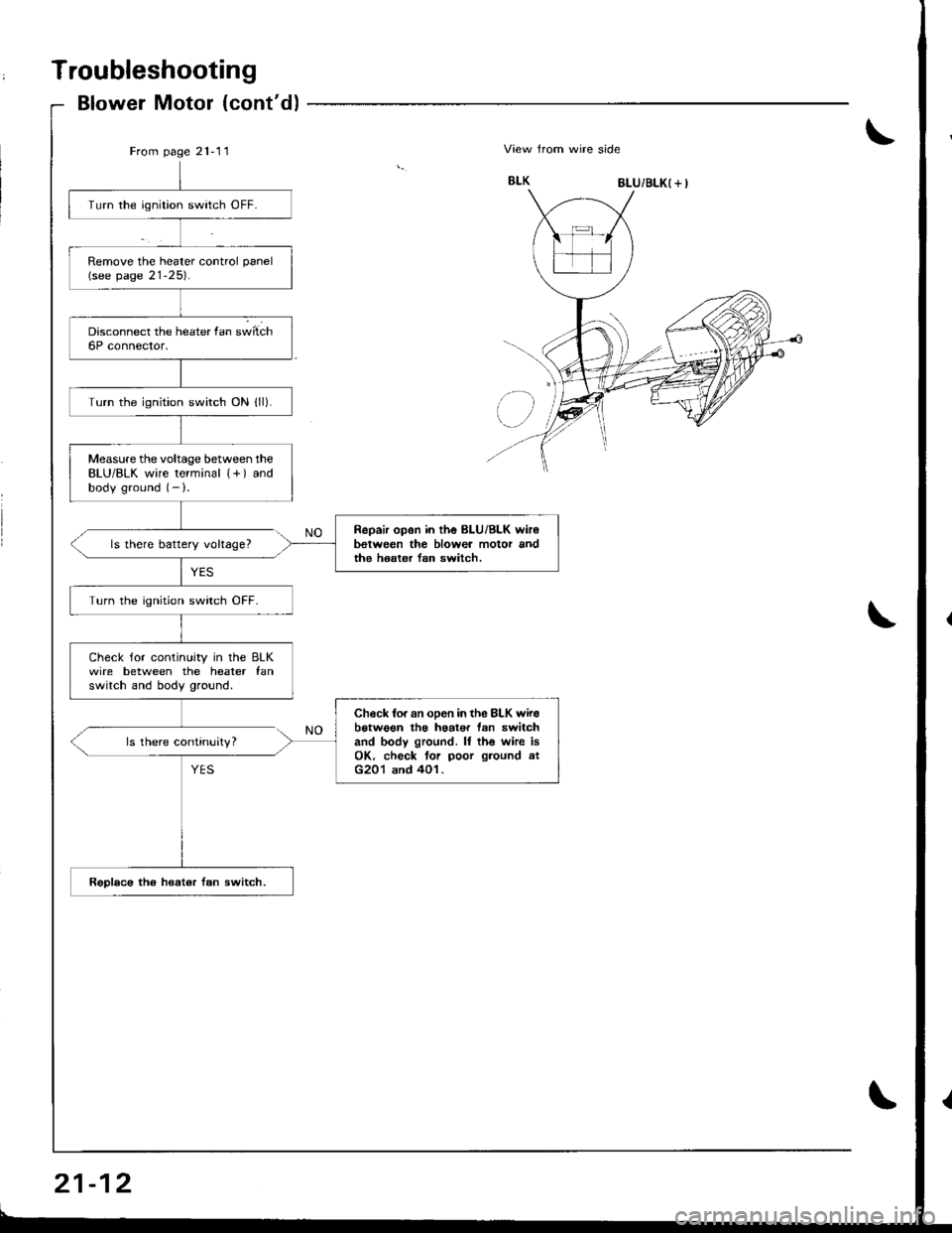
Blower Motor (cont'd)
From page 21-11\View from wire side
8LU/BLK( + I
Turn the ignition switch OFF.
Remove the heater control panel(see page 21-25).
Turn the ignition switch ON lll).
Measure the voltage between theBLU/BLK wire terminal {+) andbody ground (- ).
Repair open in the BLU/Bl-K wir6between the blowea motor andthe hoster lsn switch.ls there battery voltage?
Turn the ignition swirch OFF.
Check for continuity in the BLKwire between the heater fanswitch and body ground.
Check fo. an oDen in th6 8LK wirebotwo€n th€ haat€r tan switchand body ground. ll th6 whe isOK. check tor poor ground atG201 and 401.
Rsplac€ the heat€r fan switch.
ls there continuity?