heater HONDA INTEGRA 1998 4.G Repair Manual
[x] Cancel search | Manufacturer: HONDA, Model Year: 1998, Model line: INTEGRA, Model: HONDA INTEGRA 1998 4.GPages: 1681, PDF Size: 54.22 MB
Page 1476 of 1681
Air Deliver| (cont'd)
- How the Circuit Works
The air delivery system directs the flow of air used
by the heater and air conditioner systems.
Mode Selection
Mode selection is controlled by the mode switches in
the heater control panel and the mode control motor.
When you select a specific mode, voltage is applied
through the dimming control circuit to the LED, which
comes on, indicating the mode selected. Ground is
provided to the mode control motor though that
mode switch. The motor then runs until the air
control door reaches the proper position.
Fresh/Recirculation Selection
When you press the recirculation button, a ground
signal is sent from the heater control panel to the
recirculation control motor. The motor lhen runs
until the recirculation door reaches the opposite
Dosition. When the recirculation button is in the
REC position, battery voltage is applied through the
dimming control circuit to the recirculate LED, and
the LED comes on.
Refer to the Service Manual (Section 21, Heate0 for
specif ic tests or troubleshooting procedures.
61-2
Page 1479 of 1681
A/C Gompressor Controls (conrd)
- How the Circuit Works
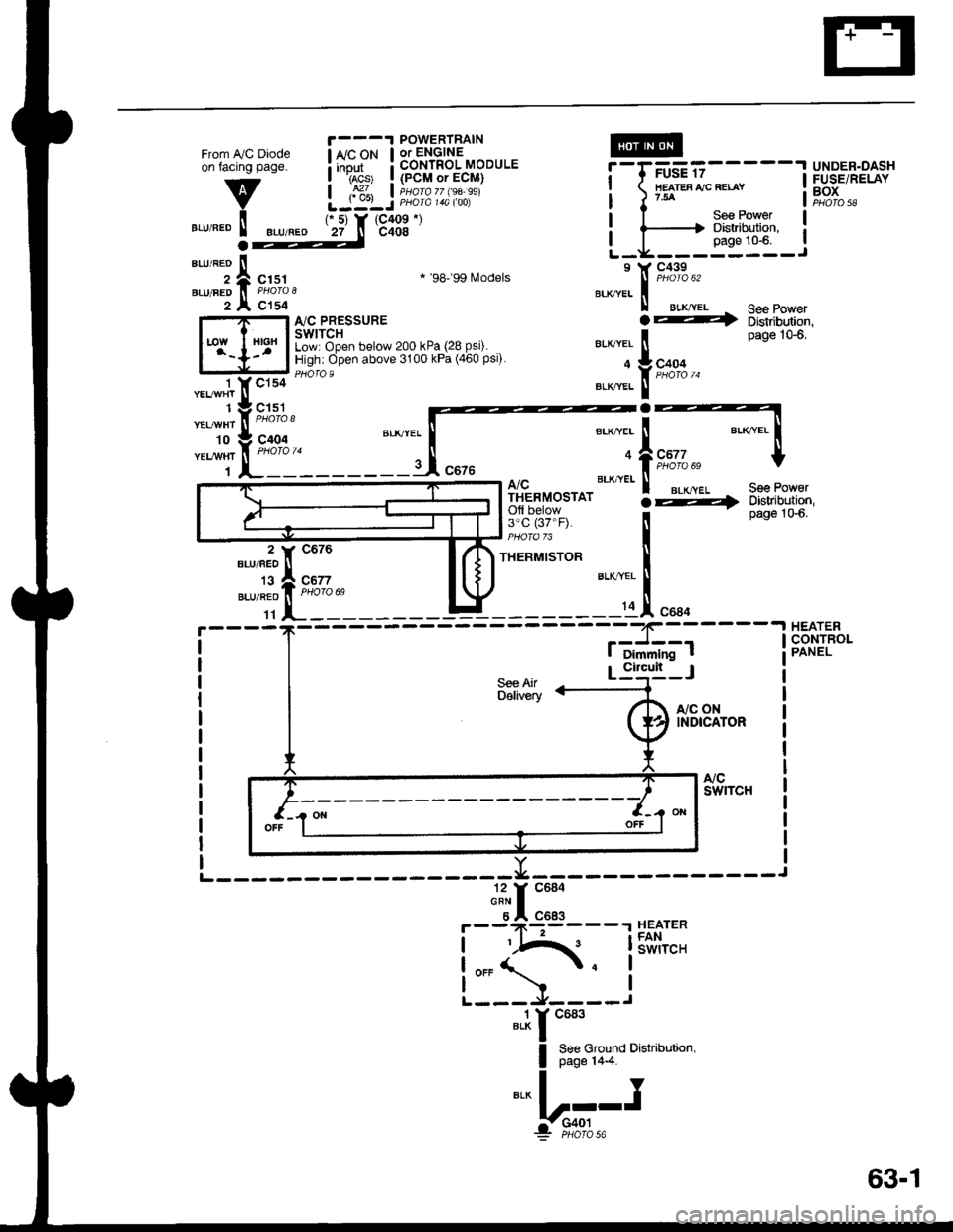
Battery voltage is supplied through fuse 56 to the
A,/C compressor clutch relay contacts at all times.
With the ignition switch in ON (ll), voltage is applied
to the coil of the A,/C compressor clutch relay
through fuse 17. When you push the A,/C switch
ON, and the heater fan switch is in posation 1, 2, 3,
or 4, a "ground" input is provided to the engine or
powertrain control module (ECM or PCM) through
the A,/C thermostat and the A,/C pressure switch.
The A,/C compressor clutch relay is grounded by the
engine or powertrain control module (ECM or PCM).
When energized, the A,/C compressor clutch relay
allows battery voltage to turn on the A,/C
comDressor clutch,
The A,/C ON indicator light comes on when the A"/C
system is requested.
A,/C Thermostat
The A,/C thermostat is located on the evaoorator
housing. The AJC thermostat turns off the A,/C
compressor clutch if the temperature at the
evaporator goes below 3'C (37'F). This prevents
condensation from freezing on the evaporator fins
and blocking the air delivery into the passenger
compartment. The blower motor will keep running
when the sensor lurns off the compressor.
A,/C Pressure Switch
The A,/C pressure switch is located in the condenser
outlet line where refrigerant is in a high
temperature/high pressure liquid state. The switch
will sense abnormally high or low pressure, and
open the circuit. This removes ground, and the
compressor will stop running.
Refer to the Service Manual (Section 22,
Air Conditioning) for specific tests or
troubleshooting procedures.
62-2
Page 1481 of 1681
From IVC Diodeon facing page.
v
".r,".o ! ".u,".o
1 YCls4 '- --
"t"*1t ,I, ^..,
-t'I:::'
ri'fft_____:_
POWERTRAIN
! *'"P* ! 3b'nli?3'-"oou'.I rAcs' I {PCM or ECM}
| ,S1, I iuorozz $a.ssiLJ:LJ PHora 14a too)IIEATES IJC RELAY?54
UNDER.DASHFUSE/RELAYBOXPHO|O 58
r 5) Y (C409 *)
27 n c408
See PowerDistribution,page 10-6.a
";;;ic151
c154
* '98'�99 Models
I'lC PRESSURESWITCHLow: Open below 200 kPa (28 Psi).High: Open above 3100 kPa (460 Psi).
.4
See Po' erDistribution,page 106,
See PoworDbtribution,page 1G6.
A/CTHERMOSTATOfl below3'c (37"F).
THERMISTOR
S€e AirDelivery
"a*a, i
*,*rfrs,*lt-
a
BTK,"VEI i
9:1L"" t
::;1".,.
I Dimmlng t
-.I HEATER,J--- I cONrR(CONTROL
Circult
r,/c oNINDICATOR
".1r "ur'
I 8:8ffiTo
o'"u''"''n'
*!r".-
F--9*l:93----r HEATER
!iIA{. lSiii,"'.
L:5-l--i
63-1
Page 1483 of 1681
Fans (cont'd)
- How the Gircuit Works
When the ignition switch is in ON (ll), voltage is
applied to the coils of the radiator fan relay and the
condenser fan relay (with A,/C) through fuse 17.
Whenever a ground is provided to the radiator fan
relay and condenser fan relay, the relays are
energized, turning on the radiator fan motor and
condenser fan motor. The relays can be grounded
by the radiator fan switch, engine or powertrain
control module (ECM or PCM) (USA), or the A,/C
and heater lan switches via the A'lC pressure switch
and the A,/C lhermostat.
A,/C Thermostat
The A,/C thermostat is located on the evaporator
housing. The A/C thermostat turns oft the A/C
compressor clutch it the temperature at the
evaporator goes below 3'C (37"F). This prevents
condensalion from freezing on the evaporator fins
and blocking the air delivery into the passenger
compartment. lt the temperature goes below 3'C
(37'F) turning off the A"/C thermostat, and the
BLU/RED wire at the A,/C diode was the only wire
providing ground to the condenser and radiator
fan relays (A,/C switch on, heater fans switch on,
radiator fan switch open, and ECM or PCM fan
controi output not grounded), the relay will
deenergize removing voltage from the condenser
and radiator fan motors causing them to stop
running.
A,/C Pressure Switch
The AJC oressure switch is located in the condenser
outlet line where refrigerant is in a high
temperature/high pressure liquid state. The A,/C
switch turns off the A,/C compressor clutch if it
senses abnormally high or low pressure. lf the A'lC
pressure switch opens, and the BLU/RED wire at
the A/C diode was the only wire providing ground
to the condenser and radiator fan relays (L/C switch
on, heater fans switch on, radiator lan switch open'
and ECM or PCM fan control output not grounded),
the relay will deenergize removing voltage from the
condenser and radiator fan motors causing them to
stop running.
A./C Diode
This diode orevents the radiator fan switch f rom
grounding the "A'lC ON" input to the engine or
powertrain control module (ECM or PCM).
Refer to the Service Manual (Section 23, Electrical)
for specific tests or troubleshooting procedures.
63-3
Page 1529 of 1681
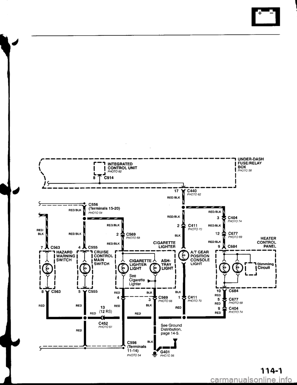
UNOER-DASHFUSE/RELAYBOXI
t
I
,
r-1 TNTEGRATEoI I coNTRoL UNIT| | PHOfO 62
J
xa
c440
A &??f,,""'"'u-ror
I PHora 51
il,.,.::r---j
Oerminals-;;i3L*
4 :---
i ! "ro".*l
1'&! ".0"*l ,flsx'"*
, .1, "uu, o I "uuu "eo "'*
!t'-lF'r HAZABD r-lF'r CRUTSE rE==I I IWARNTNG | | lCONrRoLl I
i6i**" i6i***'. i6ii€#16l*"" igi***'. i6!€Hf=ri
iLi iJ.i Ll-'sryi:8
f
cs63 s
f
csss "?L--- j:
"'"1
"* ,ri*,";f ".o
"l
-;-.;FI-
".o I ir-u:r'out I
L----Js:::,--,-"'
FED/BLK
FEO/BLK
SLK
FEO/BLK
CIGABETTELIGHTER
c404
c67?
c684
HEATERCONTROLPANEL
C411 FEO/BLK
12
FED/BLK
I
BBril"l
I
@
r
I
I
I
I
I
I
I@@
u_c684
C677
c404
10FEO
RED
9BED
I
J'
-------J
1 14-1
Page 1578 of 1681

67. Below Center of Dash, Left of Heater Unit70. Below Right Side of Front Console
68. Behind Front Console Panel71. Below Bear Console
69. Behind Center ot Dash72. Below Glove Box
201-11
Page 1606 of 1681
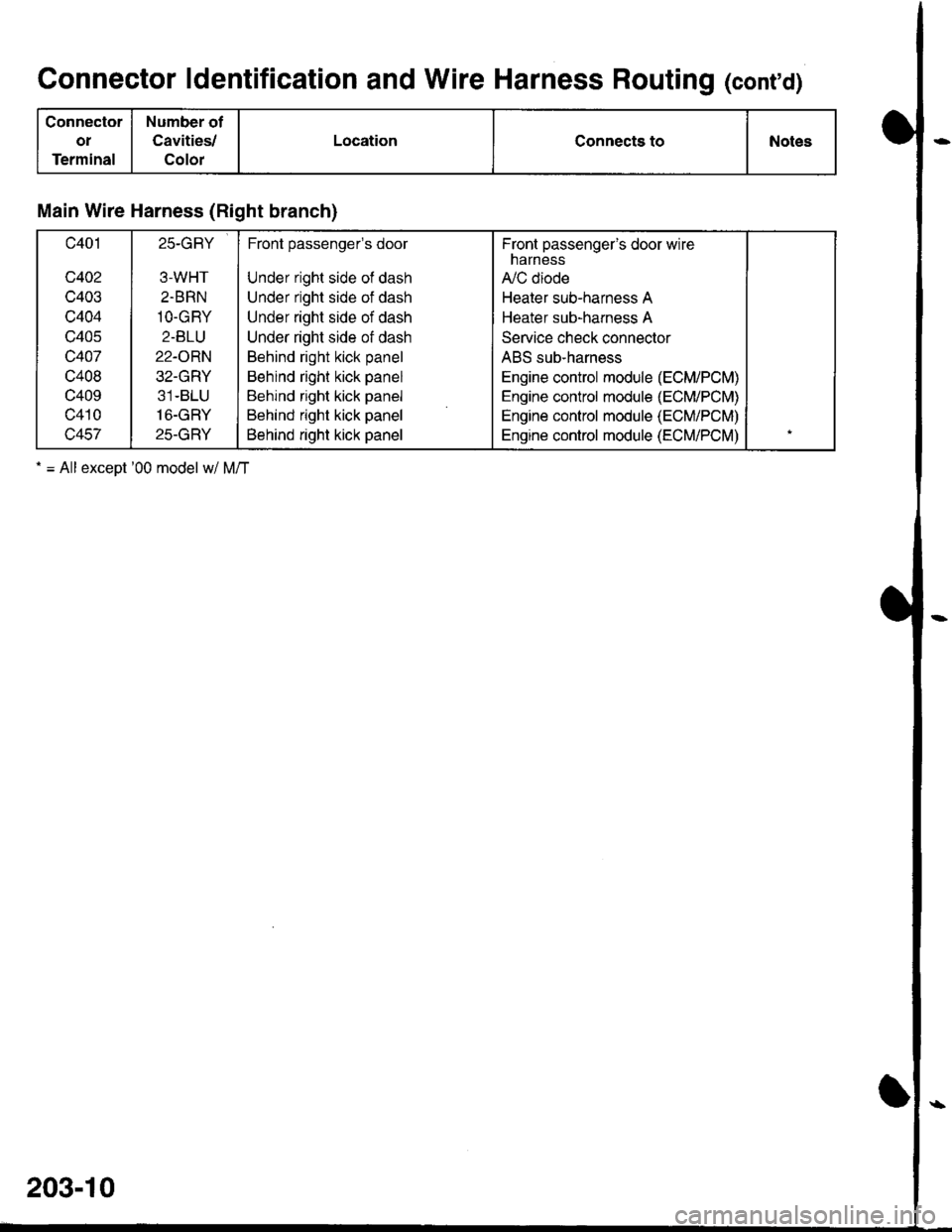
Connector ldentification and Wire Harness Routing (cont'd)
Connector
oI
Terminal
Number of
Cavities/
Color
LocationConnects toNotes
Main Wire Harness (Right branch)
c401
c402
c403
c404
c405
c407
c408
c409
c410
c457
25-GRY
3-WHT
2.BRN
1O-GRY
2-BLU
22-ORN
32-GRY
31-BLU
16-GRY
25-GRY
Front passengels door
Under right side of dash
Under right side of dash
Under right side of dash
Under right side of dash
Behind right kick panel
Behind right kick panel
Behind right kick panel
Behind right kick panel
Behind right kick panel
Fronl passenger's door wirenarness
A,/C diode
Heater sub-harness A
Heater sub-harness A
Service check connector
ABS sub-harness
Engine control module (ECM/PCM)
Engine control module (ECM/PCM)
Engine control module (ECM/PCM)
Engine control module (ECM/PCM)
. = All exceot '00 model w/ M/T
203-10
Page 1628 of 1681
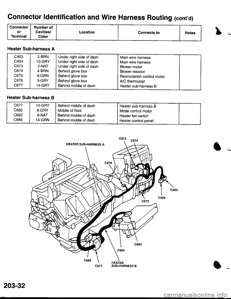
Connector ldentification and Wire Harness Routing (cont'd)
Connector
or
Terminal
Number of
Cavities,/
Color
LocationConnects toNotes
Heater Sub-harness A
c403
c404
uo /.t
uo/c
tJo/o
2-BRN
1O-GRY
2-NAT
4-BRN
4-GRN
3-GRY
14.GBY
Under right side of dash
Under right side of dash
Under right side of dash
Behind glove box
Behind glove box
Behind glove box
Behind middle of dash
Main wire harness
Main wire harness
Blower motor
Blower resistor
Recirculation control motor
A,/C thermostat
Heater sub-harness B
Heater Sub-harness B
c677
c682
tJOat.t
c684
14-GRY
8-GRY
6.NAT
14.GRN
Behind middle of dash
Middle of floor
Behind middle of dash
Behind middle of dash
Heater sub-harness B
Mode control motor
Heater fan switch
Heater control panel
HEATER SUB.HARNESS A
c684
HEATER
203-32
SUB.HARNESS B
Page 1633 of 1681
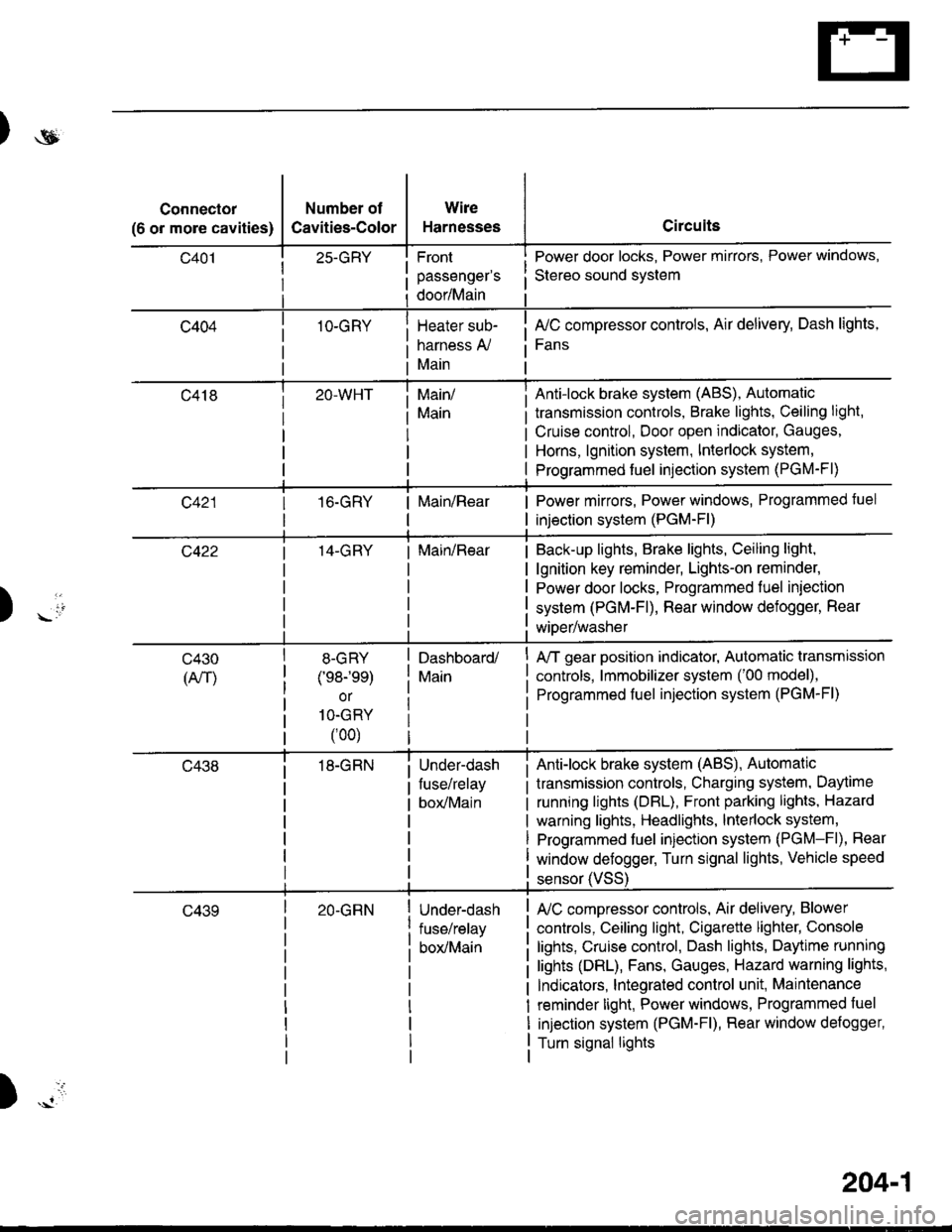
)ot
Connector
(6 or more cavities)
Number of
Cavities-Color
25-GRY
1O-GRY
Wire
Harnesses
Front
passenger's
door/Main
Heater sub-
harness A,/
Main
Circuits
Power door locks, Power mirrors, Power windows,
Stereo sound svstem
fuC compressor controls, Air delivery, Dash lights,
Fans
transmission controls, Brake lights, Ceiling light,
Cruise control, Door open indicator, Gauges,
Horns, lgnition system, Interlock system,
Programmed fuel injection system (PGM-Fl)
Main/
Main
Anti-lock brake system (ABS), Automatic
16.GRYMain/RearPower mirrors, Power windows, Programmed tuel
injection system (PGM-Fl)
14-GRYMain/RearBack-up lights, Brake lights, Ceiling light,
lgnition key reminder, Lights-on reminder,
Power door locks, Programmed fuel iniection
system (PGM-Fl), Rear window defogger, Rear
wiDer/washer) -io
tl
c430
(An)
8-GRY
(e8-'ee)
or
1O-GRY
(00)
18-GRN
Dashboard/
Main
Under-dash
fuse/relay
box/Main
A/T gear position indicator, Automatic transmission
controls, lmmobilizer system ('00 model),
Programmed fuel injection system (PGM-Fl)
Anti-lock brake system (ABS), Automatic
transmission controls, Charging system, Daytime
running lights (DBL), Front parking lights, Hazard
warning lights, Headlights, lnterlock system,
Programmed fuel injection system (PGM-Fl), Rear
window defogger, Turn signal lights, Vehicle speed
c43920-GRNUnder-dash
fuse/relay
box/Main
sensor (VSS
L/C compressor controls, Air delivery, Blower
controls, Ceiling light, Cigarette lighter, Console
lights, Cruise control, Dash lights, Daytime running
lights (DRL), Fans, Gauges, Hazard warning lights,
Indicators, lntegrated control unit, Maintenance
reminder light, Power windows, Programmed fuel
injection system (PGM-Fl), Rear window defogger,
Turn signal lights
)
204-1
Page 1635 of 1681
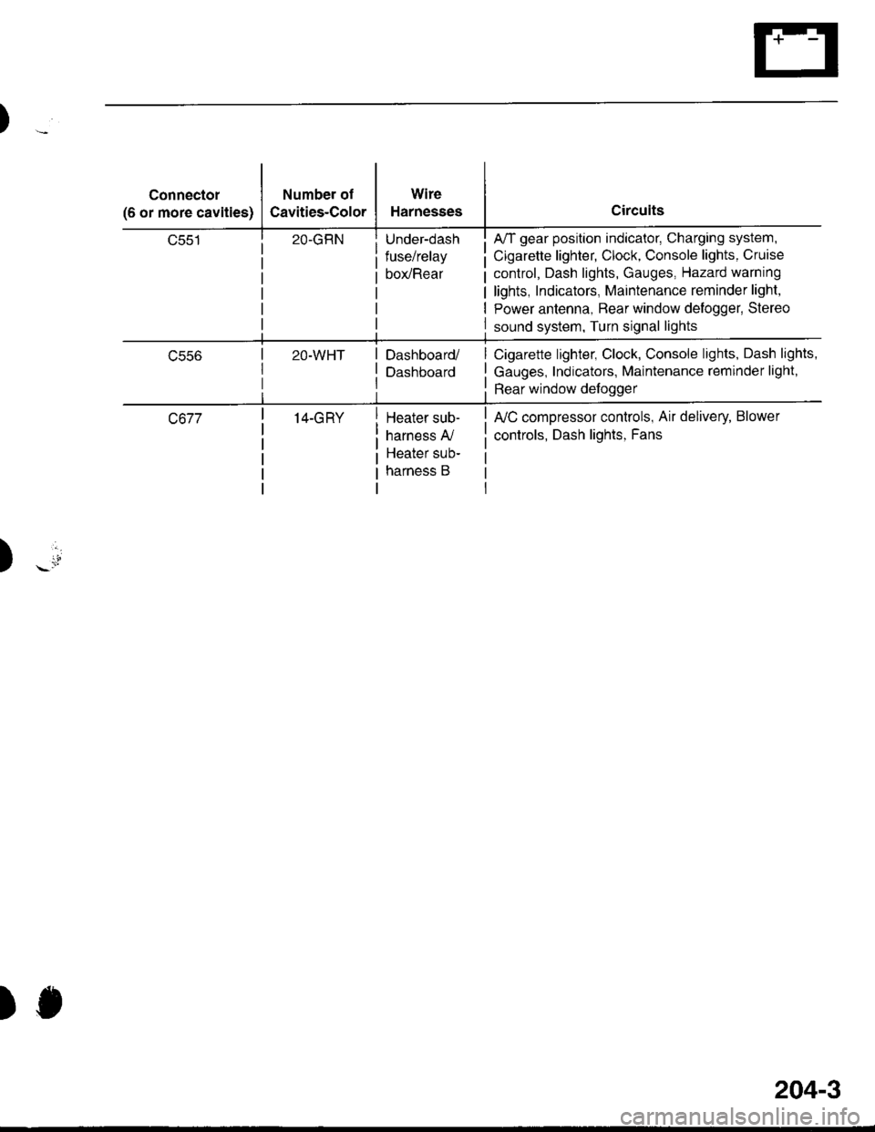
Connector
(6 or more cavities)
Number of
Cavities-Color
Wire
Harnesses
Under-dash
fuse/relay
box/Rear
A/T gear position indicator, Charging system,
Cigarette lighter, Clock, Console lights, Cruise
control, Dash lights, Gauges, Hazard warning
lights, Indicators, Maintenance reminder light,
Power antenna, Bear window delogger, Stereo
sound system, Turn signal lights
ucco2O-WHTDashboard/
Dashboard
Cigarette lighter, Clock, Console lights, Dash lights,
Gauges, Indicators, Maintenance reminder light,
Rear window defoggerrtl
c67714-GRYHeater sub-
harness A,/
Heater sub-
harness B
fuC compressor controls, Air delivery, Blower
controls, Dash lights, Fans
)
)J
204-3