power steering fluid HONDA INTEGRA 1998 4.G Owner's Manual
[x] Cancel search | Manufacturer: HONDA, Model Year: 1998, Model line: INTEGRA, Model: HONDA INTEGRA 1998 4.GPages: 1681, PDF Size: 54.22 MB
Page 702 of 1681
Strsring Rack Roarssmbly
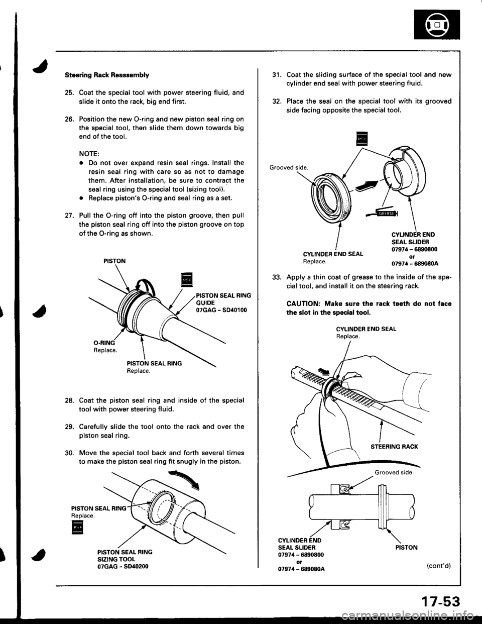
25. Coat the special tool with power steering fluid, and
slide it onto the rack, big end first.
26. Position the new O-ring and new piston seal ring on
the special tool, then slide them down towards big
end of the tool.
NOTE:
. Do not over expand resin seal rings. Install the
resin seal ring with care so as not to damage
them. After installation. be sure to contract the
seal ring using the specialtool (sizing tool).
. Replace piston's O-ring and sesl ring as a set.
27. Pull the O-ring off into the piston groove, then pull
the piston seal ring off into the piston groove on top
of the O-ring as shown.
Coat the piston seal ring and inside of the special
tool with power steering fluid.
Carefullv slide the tool onto the rack and over the
piston seal ring.
30. Move the special tool back and forth several times
to make the piston seal ring fit snugly in the piston.
28.
29.
PISTON
Replace.
31.Coat the sliding surface of the special tool and new
cylinder end seal with power steering fluid,
Place the seal on the special tool with its grooved
side facing opposite the special tool.
Grooved side.
CYLINOER END SEALReplace. 0797,t - 68D8OA
Apply a thin coat of grease to the inside of the spe-
cial tool, and install it on the steering rack.
CAUTION: Make sure the rack tecth do not lace
the 3lot in the special tool.
CYLINDER END SEALReplace.
CYLINDERSEAL SLIDER07974 - 6890800ot(cont'd)07974 - 6A1080A
17-5�3
Page 703 of 1681
Power Steering Gearbox
Reassembly {cont'd}
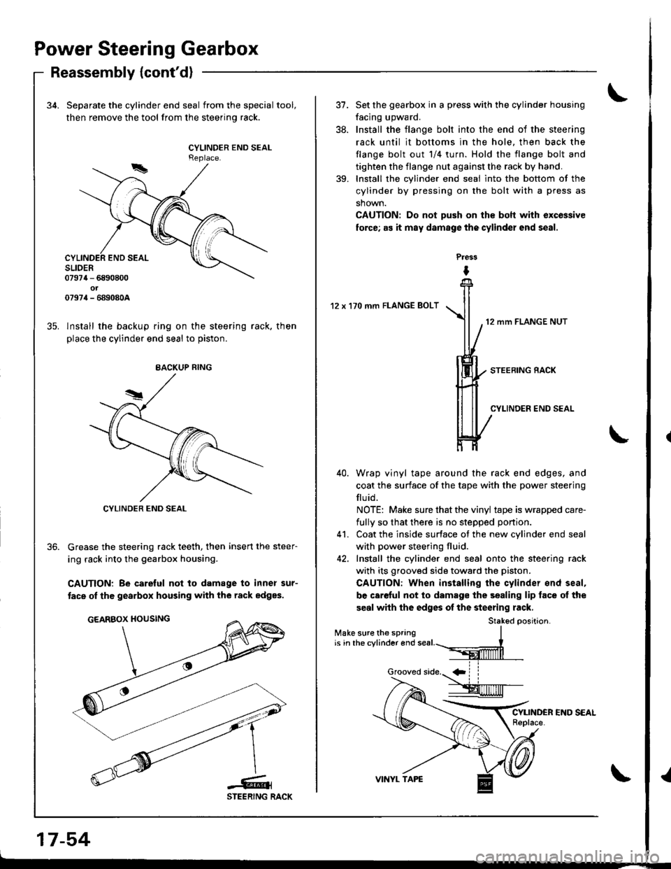
34. Separate the cylinder end seal from the special tool,
then remove the tool from the steerino rack.
CYLINDER END SEALReplace.
lnstall the backup ring on the steering rack. then
place the cylinder end seal to piston.
Grease the steering rack teeth, then insert the steer-
ing rack into the gearbox housing.
CAUTION: Be carelul not to damage to inner sur-
tace of the gearbox housing with the rack edges.
BACKUP BING
CYLINDER END SEAL
17-54
37.
38.
Set the gearbox in a press with the cylinder housing
facing upward.
Install the flange bolt into the end of the steering
rack until it bottoms in the hole. then back the
tlange bolt out 1/4 turn. Hold the flange bolt and
tighten the flange nut against the rack by hand.
Install the cylinder end seal into the bottom of the
cylinder by pressing on the bolt with a press as
shown.
CAUTION: Do not push on th€ boh with excossive
lorce; as it may damage thecylinder end seal.
Press
I
12 x 170 mm FLANGE BOLT
12 mm FLANGE NUT
Wrap vinyl tape around the rack end edges, and
coat the surface of the tape with the power steering
flu id.
NOTE: Make sure that the vinyl tape is wrapped care-
fully so that there is no stepped ponion.
Coat the inside surface of the new cvlinder end seal
with power steering fluid.
Install the cylinder end seal onto the steering rack
with its grooved side toward the piston.
CAUTION: When installing the cylinder end seal,
be careful not to damage the sealing lip face of the
seal with the edges of the steering rack,
Stak6d oosition.
39.
41.
Make sure the springis in the cylinder end
Page 708 of 1681
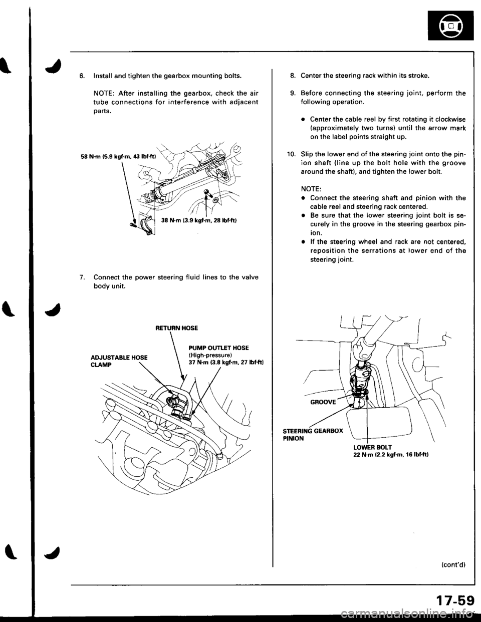
Install and tighten the gearbox mounting bolts.
NOTE: After installing the gearbox, check the air
tube connections for interference with adjacent
parts.
58 N.m 15.9 kgl.m, 43 lbf.ftl
Connect the power steering fluid lines to the valve
body unit.
7.
38 N.m {3.9 kgt m, 28 lbf.ftl
RETURN HOSE
PUMP OUTI.TY HOSE(High-pressure)
37 N.m (3.8 kgf.m, 27 lbt.ftl
Center the steering rack within its stroke.
Before connecting the steering joint, perform the
lollowing operation.
. Center the cable reel by first rotating it clockwise(approximately two turns) until the arrow mark
on the label points straight up,
Slip the lower end of the steering ioint onto the pin-
ion shaft {line up the bolt hole with the groove
around the shaft), and tighten the lower bolt.
NOTE:
. Connect the steering shaft and pinion with the
cable reel and steering rack centered.
. Be sure that the lower steering joint bolt is se-
curely in the groove in the steering gearbox pin-
ion.
o lf the steering wheel and rack are not centered,
reoosition the serrations at lower end of the
steering joint.
(cont'd)
LOWER BOLT22 N.m {2.2 kgf.m, 16 lbf.ft,
17-59
Page 710 of 1681
)
)
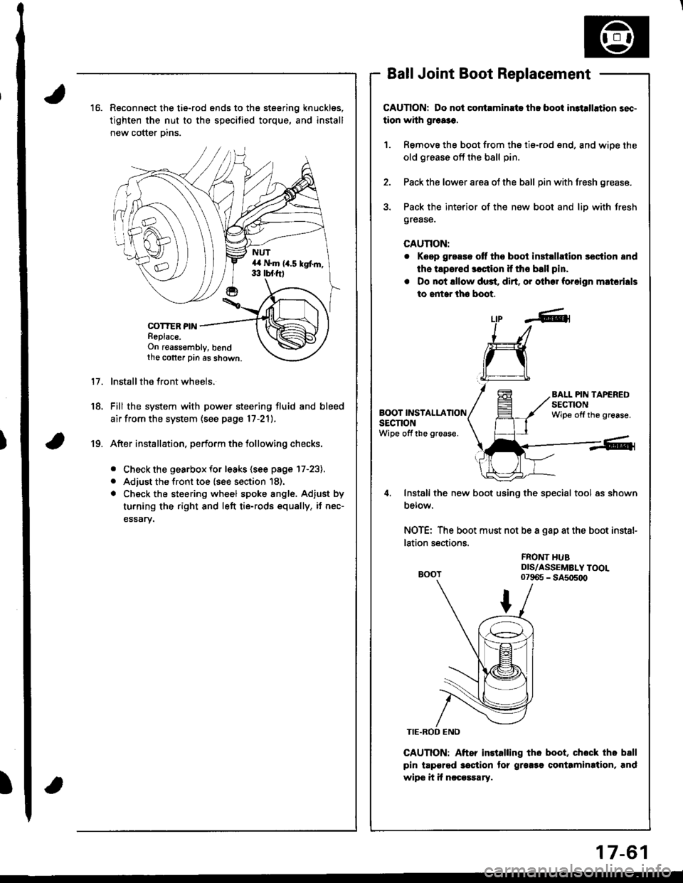
16.Reconnect the tie-rod ends to the steering knuckles,
tighten the nut to the specified torque, and install
new cotter Dins.
COT?ER PINReplace.On reassembly, bendthe cotter pin as shown.
lnstall the front wheels.
Fill the system with power steering fluid and bleed
air from the system (see page 17-21).
After installation, perform the tollowing checks.
. Check the gearbox for leaks (see page l7-23).
. Adjust the front toe (see section 18).
. Check the steering wheel spoke angle. Adjust by
turning the right and left tie-rods equally, it nec-
essary.
Ball Joint Boot Replacement
CAUTION: Do not contaminste th! boot in3tllhtion sec-
tion with grca3o.
1. Remove the boot from the tie-rod end, and wiDe the
old grease off the bsll pin.
2. Pack the lower area of the ball pin with fresh grease.
3. Pack the interior of the new boot and liD with Jresh
grease.
CAUTION:
r Keep grease off tho boot inst.llrtion section 8nd
ths tapered 3cction if tho ball pin.
. Do not lllow du3t. dirt. or other foreign matcrials
to entar lh6 boot.
17.
18.
Lfp -A-1
L:I
ru
Install the new boot using the special tool as shown
Derow.
NOTE: The boot must not be a gap at the boot instal-
lation sections.
CAUTION: Aftor installing tho boot, chock tho ball
pin tapgrgd 3oction tor grorsg conttmination, and
wipe it if nccossary.
BALL PIN TAPEREDsEcnoNWipe offthe grease.BOOT INSTALLATIONsEcnoNWipe off the groaso.
19.
FROI{T HUBDIS/ASSEMBLY TOOL07965 - SA5o5o0
17-61
Page 1406 of 1681
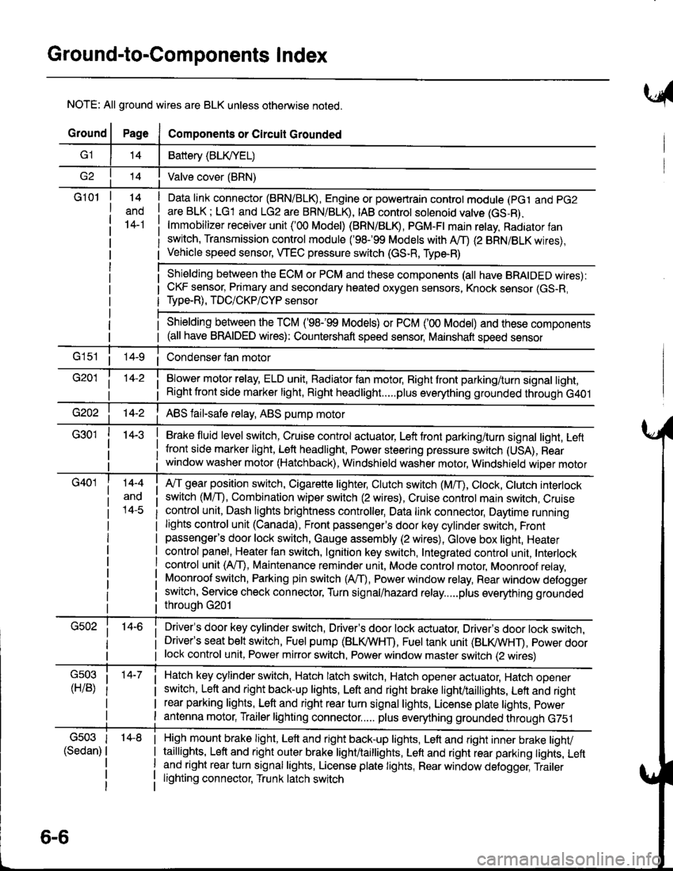
Ground-to-Components I ndex
NOTE: All ground wires are BLK unless otherwise noted.
GroundPageComponents or Circuit Grounded
Battery (BLIVYEL)
--t'I Valve cover (BRN)
G101t.+
and
14-1
Daia link connector (BRN/BLK), Engine or powertrain controt module (pct and pG2
are BLK; LG1 and LG2 are BRN/BLR, IAB controt solenoid valve (GS-B),
lmmobilizer receiver unit ('00 Model) (BRN/BLR, PGM-Ft main retay, Radiator fan
switch, Transmission control module ('98.�99 Models with MD (2 BRN/BLK wires),
Vehicle speed sensor, WEC pressure switch (GS-R, Type-R)
Shielding between the ECM or PCM and these components (all have BRAIDED wires):
CKF sensor, Primary and secondary heated oxygen sensors, Knock sensor (GS-R,
Type-R), TDC/CKP/CYP sensor
Shielding between the TCM ('98-'99 Models) or PCM ('00 Model) and these components(all have BRAIDED wires): Countershaft speed sensor, Mainshaft speed sensor
G1s1 ii Condenser fan motor
Brake fluid level switch, Cruise control actuator, Left front parking/turn signal light, Left
front side marker light, Left headlight, Power steering pressure switch (USA), Rear
window washer motor (Hatchback), Windshield washer motor, Windshield wiper motor
14-3
Blower motor relay, ELD unit, Badiator fan motor, Right front parking/turn signal light,
Right front side marker light, Right headlight.....plus everything grounded through G401
ABS fail-safe relay, ABS pump motor
G40114-4
ano
l4-c
A,/T gear position switch, Cigarette lighter, Clutch switch (M,/T), Ctock, Ctutch interlock
switch (MfD, Combination wiper switch (2 wires), Cruise control main switch, Cruise
control unit, Dash lights brightness controller, Data link connector, Daytime running
lights control unit (Canada), Front passenger's door key cylinder switch, Frontpassenger's door lock switch, Gauge assembly (2 wires), Glove box light, Heater
control panel, Heater tan switch, lgnition key switch, Integrated control unit, Interlock
control unit (AfI), Maintenance reminder unit, Mode control motor, Moonroof relay,
Moonroof switch, Parking pin switch (AfD, Power window relay, Rear window defogger
switch, Service check connector, Turn signal/hazard relay.....plus everything grounded
throuoh G201
Driver's door key cylinder switch, Driver's door lock actuator, Drivels door lock switch,Driver's seat belt switch, Fuel pump (BLI(/WHT), Fuel tank unit (BLI(/WHT), power doorlock control unit, Power mirror switch, Power window master switch (2 wires)
Hatch key cylinder switch, Hatch latch switch, Hatch opener actuator, Hatch ooener
switch, Left and right back-up lights, Left and right brake light/taillights, Lett and right
rear parking lights, Left and right rear turn signal lights, License plate lights, power
antenna motor, Trailer lighting connector..... plus everything grounded through G751
6-6
'14-8G503
(Sedan)
High mount brake light, Left and right back-up lights, Lett and right inner brake tighv
taillights, Left and right outer brake light/taittights, Left and right rear parking tights, Leftand right rear turn signal lights, License plate lights, Rear window detogger, Trailer
lighting connector, Trunk latch switch
Page 1602 of 1681
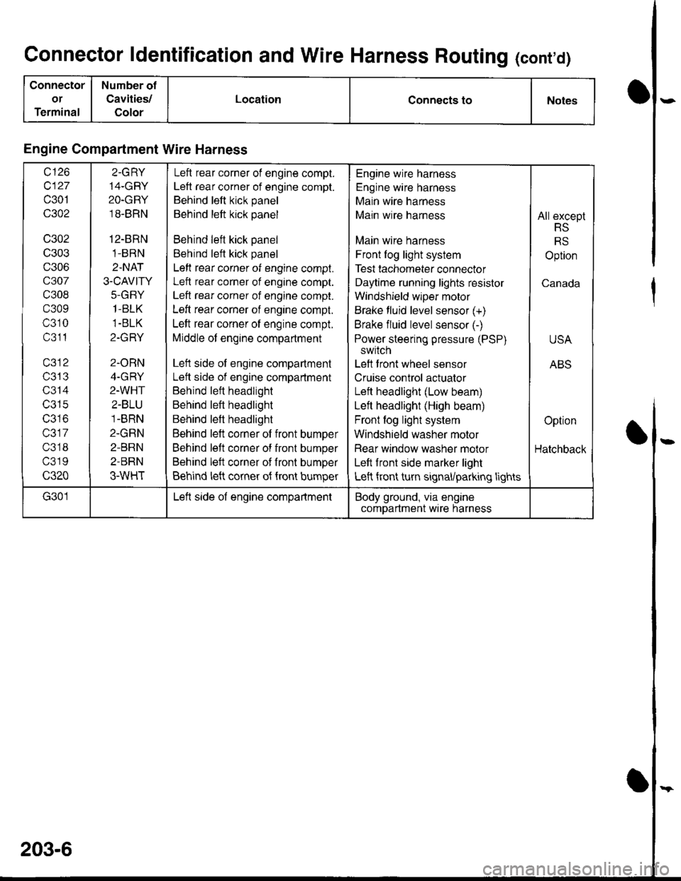
Connector ldentification and Wire Harness Routing (cont'd)
Connector
or
Terminal
Number of
Cavities/
Color
LocationConnects toNotes
Engine Compartment Wire Harness
wt10
c127
c301
c302
c302
c303
c306
c307
c308
c309
c310
c311
T/JIJ
c314
c315
IJJ IO
c317
c318
c319
c320
2.GRY
14-GBY
2O-GRY
18-BRN
12-BRN
1-BRN
2.NAT
3.CAVITY
J-(l|-I Y
1-BLK
1-BLK
Z-IfFI T
2-ORN
4-GRY
2-WHT
2-BLU
1-BRN
2-GRN
2-BRN
2-BRN
3-WHT
Left rear corner of engine compt.
Left rear corner of engine compt.
Behind left kick panel
Behind left kick panel
Behind left kick panel
Behind left kick panel
Left rear corner of engine compt.
Left rear corner of engine compt.
Left rear corner of engine compt.
Left rear corner of engine compt.
Left rear corner of engine compt.
Middle of engine compartment
Left side of engine compartment
Lett side of engine compartment
Behind left headlight
Behind left headlight
Behind left headlight
Behind left corner of front bumper
Behind left corner of front bumper
Behind left corner of fronl bumper
Behind left corner of {ront bumper
Engine wire harness
Engine wire harness
Main wire harness
Main wire harness
Main wire harness
Front log light system
Test tachometer connector
Daytime running lights resistor
Windshield wlper motor
Brake fluid level sensor (+)
Brake fluid level sensor (-)
Power steering pressure (PSP)
switch
Left front wheel sensor
Cruise control actuator
Left headlight (Low beam)
Left headlight (High beam)
Front fog light system
Windshield washer motor
Rear window washer molor
Left front side marker light
Left front turn signal/parking lights
All except
RS
RS
Option
Canada
USA
ABS
Option
Hatchback
G301Left side of engine compartmentBody ground, via engine
comDartment wire harness
203-6
Page 1655 of 1681
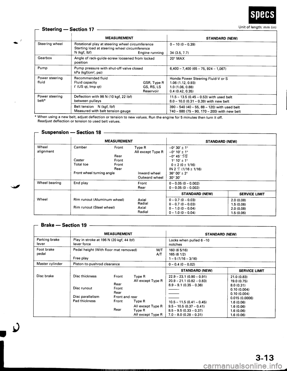
MEASUREMENTSTANDARD (NEWI
Steering wheelRotational play at steering wheel circumferenceStarting load at steering wheel circumferenceN (kgf, lbf) Engine running
0 - 10 (0 - 0.39)
34 (3.5,7 .71
GearboxAngle of rack-guide-screw loosened from lockedoosition20'MAX
PumpPump pressure with shut-off valve closedkPa (kgf/cm,, psi)6,400 - 7,400 (65 - 75, 924 - 1,067],
Power steeringfluidRecommended fluidFluid capacity GSR, Type Rf (US qt, lmp qtl cS, RS, LSReservoir
Honda Power Steering Fluid-V or S1.06 (1.12,0.93)
1.0 (1.06,0.88)
0.4 (0.42, 0.35)
Power steeringbelt*Deflection with 98 N (10 kgf,22 lbflbetween pulleys1 1.5 - 13.5 (0.45 - 0.531 with used belt8.0 - 10.0 (0.31 - 0.39) with new belt
Belt tension N (kgf, lbf)Measured with belt tension gauge390 - 540 (40 - 55, 88 - 120) with used belt740 - 880 (75 - 90, 170 - 2001with new belt
SteeringSection 17
* When using a new belt, adjust deflection or tension to new values. Run the engine for 5 minutes then turn it off.Readiust deflection or tension to used belt values.
Suspension - Section 18
BrakeSection 19
Unit of length: mm (in)
$t
MEASUREMENTSTANDARD (NEWI
WheelalignmentCamber Front Type RAll except Type RRearCaster FrontTotal toe FrontRearFront wheel turning angle Inward wheelOutward wheel
-0'30'r 1"-0' 10'r 1.-0" 45'�1?:i3i1. 10'�1 1.0!210!1116!,lN 2 lf (t7t6 1 1716136. 00'1 2"30'30'
Wheel bearingEnd play FrontRear0 - 0.05 (0 - 0.002)0 - 0.05 (0 - 0.002)
WheelRim runout (Aluminum wheel) AxialRadialRim runout (Steel wheel) AxialRadial
STANDARD (NEW}SERVICE LIMIT
0 - 0.7 (0 - 0.03)0 - 0.7 (0 - 0.03)0 - 1.0 (0 - 0.04)0 - 1.0 (0 - 0.04)
2.0 (0.08)
1.5 (0.06)2.0 (0.08)1.5 (0.06)
MEASUREMENTSTANDARD (NEW}
Parking brakeleverPlay in stroke at 196 N (20 kgf,44 lbf)lever forceLocks when oulled 6 -10
notches
Foot brakepedalPedal height (With floor mat removed)
Free play
M/TAtT160 (6 5/161165 rc 1nl1-5(1/16-3/16)
Master cylinderPiston-to-oushrod clearance0 - 0.4 (0 - 0.021
Disc brakeDisc thickness Front Type RAll except Type RRearDisc runout FrontRearDisc parallelism Front and rearPad thickness Front Type R
All except Type RRear Type RAll except Type R
STANDARD (NEWISERV]CE LIMIT
22.9 - 23.1 (0.90 - 0.91120.9 - 21.1 (0.82 - 0.83)
1= t (0.35-0.361
10.5 - 11.5 (0.41 - 0.45)9.5 - 10.5 (0.37 * 0.41)8.5 - 9.5 (0.33 - 0.37)7.0 - 8.0 (0.28 - 0.31)
21.0 (0.83)19.0 (0.75)
8.0 (0.31)
0.10 (0.004)
0.10 (0.004)
0.015 (0.0006)1.6 (0.06)
1.6 (0.06)1.6 (0.06)
1.6 (0.06)
Page 1664 of 1681
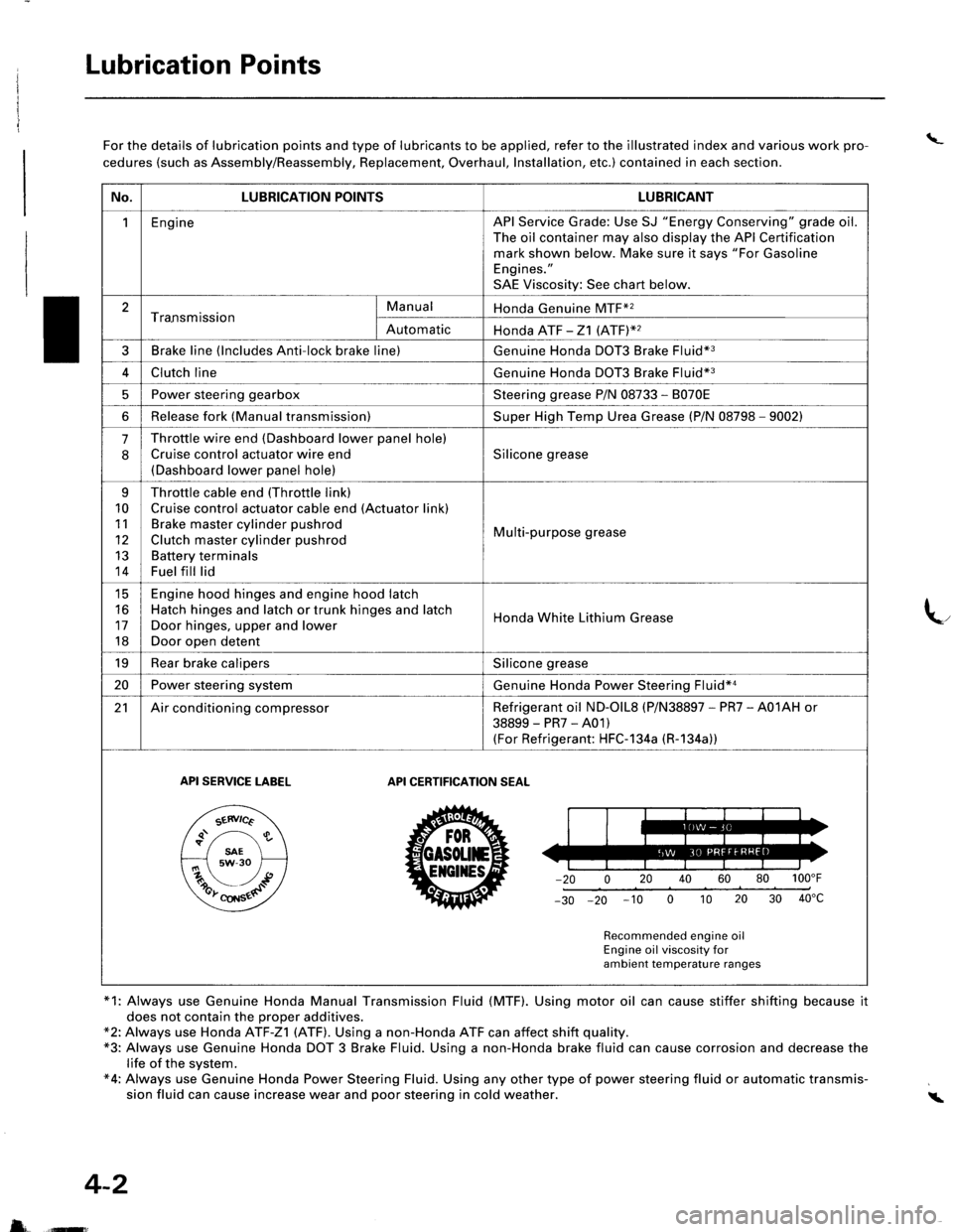
Lubrication Points
\_For the details of lubrication points and type of lubricants to be applied, refer to the illustrated index and various work pro-
cedures (such as Assembly/Reassembly, Replacement, Overhaul, Installation, etc.) contained in each section.
*1: Always use Genuine Honda Manual Transmission Fluid (MTF). Using motor oil can cause stiffer shifting because it
does not contain the proper additives.*2: Always use Honda ATF-Z1 (ATF). Using a non-Honda ATF can affect shift quality.*3: Always use Genuine Honda DOT 3 Brake Fluid. Using a non-Honda brake fluid can cause corrosion and decrease thelife of the system.*4: Always use Genuine Honda Power Steering Fluid. Using any other type of power steering fluid or automatic transmis-sion fluid can cause increase wear and poor steering in cold weather.i
4-2
5 ffi
No.LUBRICATION POINTSLUBRICANT
1EngineAPI Service Grade: Use SJ "Energy Conserving" grade oil.The oil container may also display the API Certificationmark shown below. Make sure it says "For GasolineEngines."
SAE Viscosity: See chart below.
2Tra.nsmissionManualHonda Genuine MTF*2
AutomaticHonda ATF -21 (ATFY2
3Brake line (lncludes Anti-lock brake line)Genuine Honda DOT3 Brake Fluid*3
4Clutch lineGenuine Honda DOT3 Brake Fluid*3
5Power steering gearboxSteering grease P/N 08733 - 8070E
6Release fork (Manual transmission)Super High Temp Urea Grease (P/N 08798 - 9002)
.J
Throttle wire end (Dashboard lower panel hole)
Cruise control actuator wire end(Dashboard lower panel hole)
Silicone grease
q
10
11
12
13
14
Throttle cable end (Throttle link)
Cruise control actuator cable end (Actuator link)Brake master cylinder pushrod
Clutch master cylinder pushrod
Battery terminalsFuel fill lid
Multi-purpose grease
tc
16
17
18
Engine hood hinges and engine hood latchHatch hinges and latch or trunk hinges and latch
Door hinges, upper and lower
Door open detent
Honda White Lithium Grease
19Rear brake calipersSilicone grease
20Power steering systemGenuine Honda Power Steering Fluid*a
21Air conditioning compressorRefrigerant oil ND-olL8 (P/N38897 - PR7 - A01AH or
38899-PR7-A01)(For Refrigerant: HFC-1 34a (R-1 34a))
API SERVICE TABELAPI CERTIFICATION SEAT
ZU30
Recommended engine oilEngine oil viscosity forambient temperature ranges