power steering fluid HONDA INTEGRA 1998 4.G User Guide
[x] Cancel search | Manufacturer: HONDA, Model Year: 1998, Model line: INTEGRA, Model: HONDA INTEGRA 1998 4.GPages: 1681, PDF Size: 54.22 MB
Page 683 of 1681
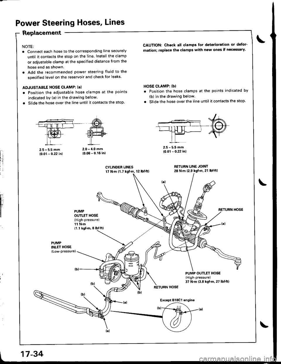
Power Steering Hoses, Lines
Replacement
NOTE:
. Connect each hose to the corresponding line securely
until it contacts the stop on the line. Install the clamp
or adjustable clamp at the specified distance from the
hose end as shown.
. Add the recommended power steering fluid to the
specified level on the reservoir and check for leaks.
ADJUSTABLE HOSE CLAMP: (al
. Position the adjustable hose clamps at the points
indicated by (a) in the drawing below.
. Slide the hose over the line until it contacts the stop.
CAUTION: Ch€ck all clamps for deterioration or defor-
mation; replace the clamps with new ones it necessary'
HOSE CLAMP: (b)
. Position the hose clamps at the points indicated by
(b) in the drawing below.
. Slide the hose over the line until itcontactsthe stop.
2.5 - 5.5 mm(0.01 - 0.22 in)
RETURN LINE JOINT28 N m 12.9 kg{'m,2'l lbf'ft|
PUMP OUTLET HOSE(High'pressure)
37 N.m (3.8 kgtm,27 lbf.ft)
2.5-5.5 mm
10.01 - 0.22 in)2.0 - {.0 mm
10.08 - 0.16 inl
CYLINDER LINES17 N.m (1.7 kgt m, 12 lbf'ft)
PUMPOUTI.IT HOSE(High-pressure)
11 N.m11.1 kgl.m,8lbJftl
PUMPINLET HOSE(Low-pressurel
RETURN HOSE
Exc.pt Bl8Cl engino
17-34
Page 684 of 1681
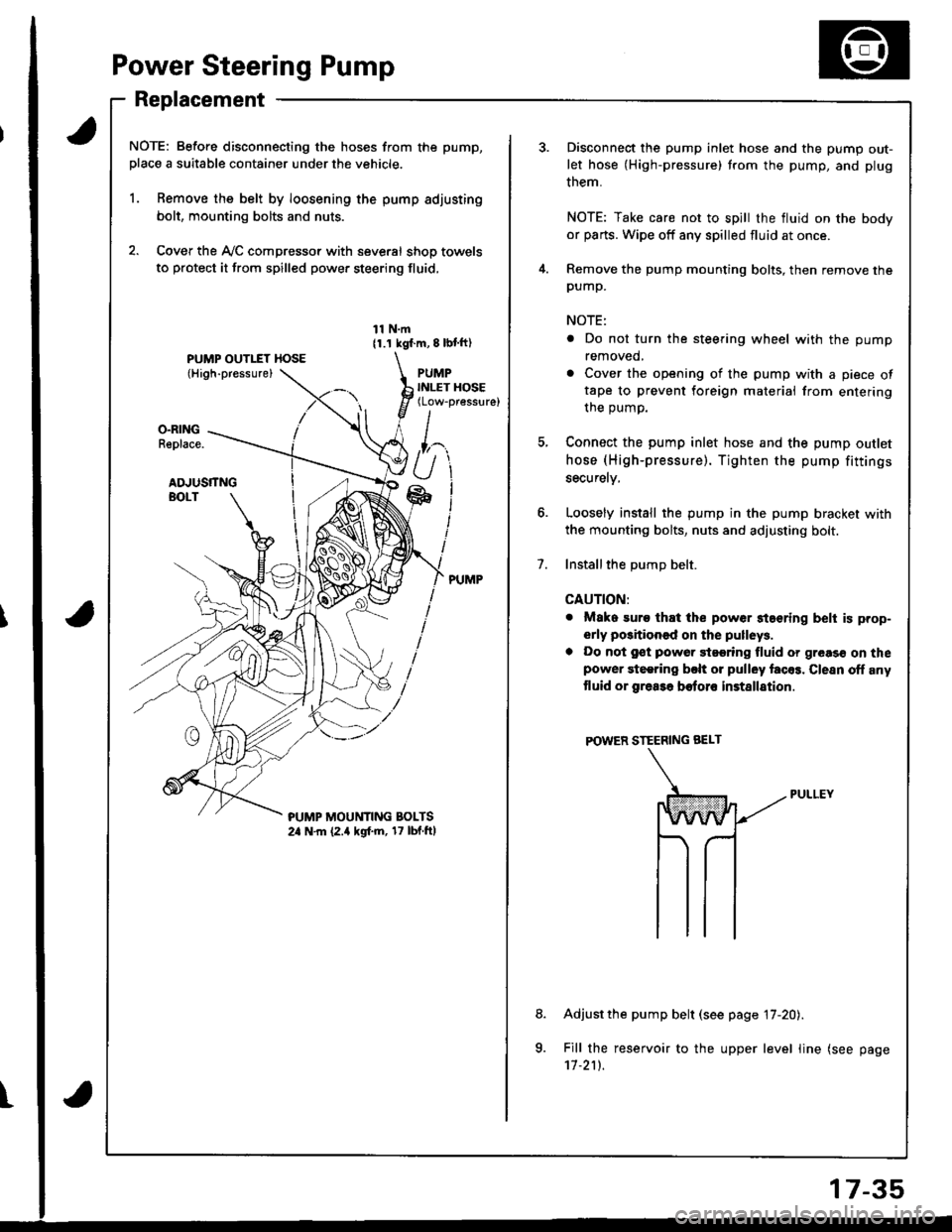
Power Steering Pump
Replacement
NOTE: Before disconnecting the hoses from the pump,
place a suitable container under the vehicle.
1. Remove the belt by loosening the pump adjusting
bolt, mounting bolts and nuts.
2. Cover the Ay'C compressor with several shop towels
to protect it from spilled power steering fluid,
11 N.m11.1 kgf.m, 8 lbl ft)
PUMPINLET HOSE(Low-pressure)
O.RINGReplace.
ADJUSTTNGBOLT
?UMP MOUt'lTlNG BOLTS2a N.m (2.a kgf.m, 17 lbf.ftl
t
7.
Disconnect the pump inlet hose and the pump out-
let hose (High-pressure) trom the pump, and plug
them.
NOTE: Take care not to spill the fluid on the body
or parts. Wipe off any spilled fluid at once.
Remove the pump mounting bolts, then remove thepump.
NOTE:
. Do not turn the steering wheel with the pump
removed,
. Cover the opening of the pump with a piece oftape to prevent foreign materiai from entering
the oumo.
Connect the pump inlet hose and the pump outlet
hose (High-pressure). Tighten the pump fittings
securelv,
Loosely install the pump in the pump bracket with
the mounting bolts, nuts and adjusting bolt.
Installthe DumD belt.
CAUTION:
. Mako suro that the power staering belt is prop-
erly positioned on the pulleys.
a Do not gst powor 9t99ring fluid or greas€ on thepower steering bclt or pulley facos. Clesn off any
tluid or grea3a botoro installation
POWER STEERING BEI-T
Adjust the pump belt (see page 17-20).
Fill the reservoir to the upper level line (see page'11.211.
8.
a
17-35
Page 685 of 1681
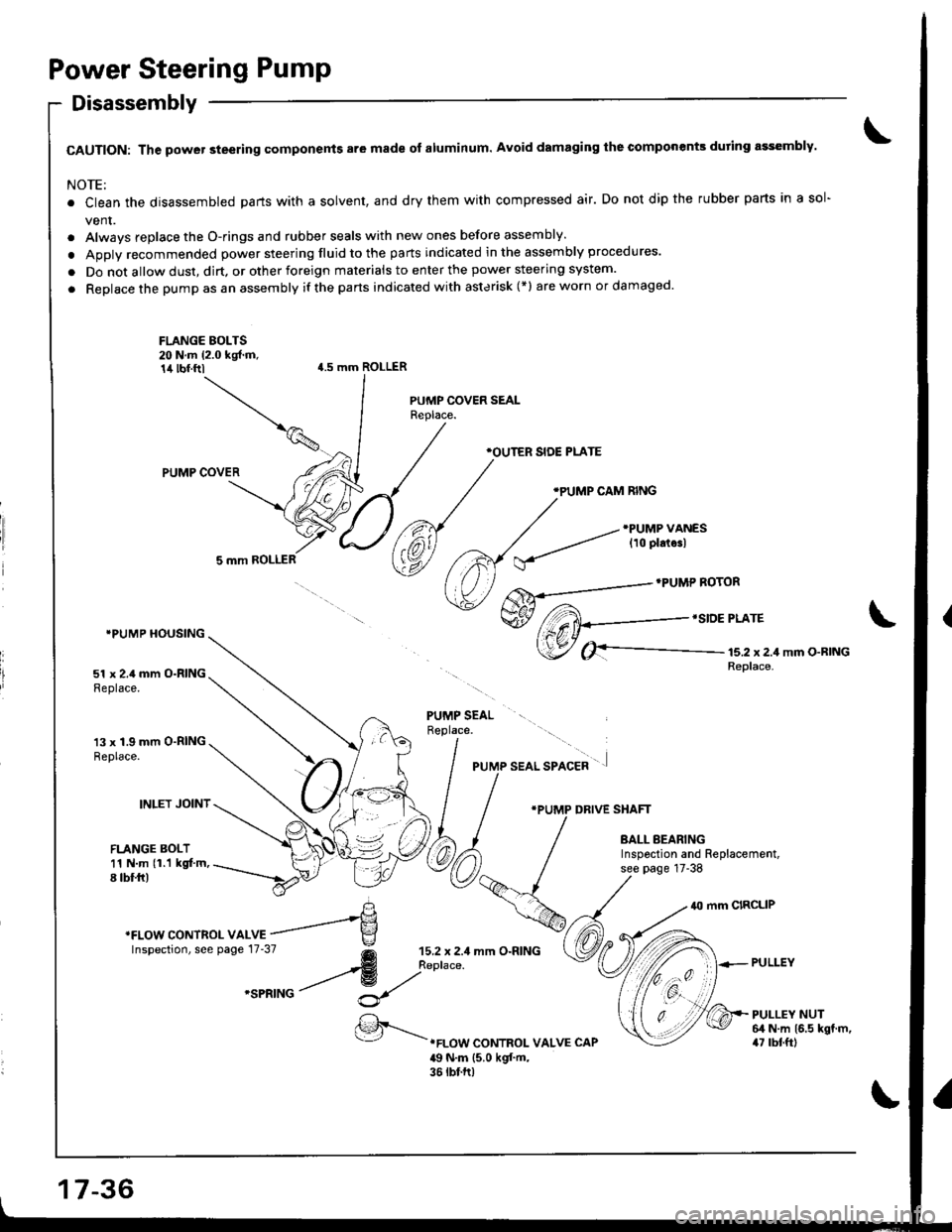
Power Steering Pump
Disassembly
CAUTION: The power steering components are made of aluminum. Avoid damaging the componenk during assembly.
NOTE:
. Clean the disassembled parts with a solvent, and dry them with compressed air. Do not dip the rubber parts in a sol-
vent.
. Always replace the O-rings and rubber seals with new ones before assembly.
. Apply recommended power steering fluid to the parts indicated in the assembly procedures.
. Do not allow dust, dirt, or other foreign materials to enter the power steering system.
. Replace the pump as an assembly if the parts indicated with asterisk (*l areworn ordamaged'
\
FLANGE BOLTS20 N.m (2.0 kgf.m,14 tbf.ftl{.5 mm ROLLER
PUMP COVER
5 mm ROLLER
IPUMP HOUSING
51 x 2.4 mm O-RINGReplace.
13 x 1.9 mm O-RINGReplace.
INLET JOINT
FLANGE BOLT11 N.m (1.1 kgt'm,8 tbf.fr)
PUMP SEALReplace.
,r"" aao, "ro"a* ' .]
*PUMP DRIVE SHAFT
BALL BEARINGInspoction and Replacement,see page 17-38
40 mm CIRCLIP
PULLEY
PULLEY NUT64 N.m 16.5 kgt.m,47 rbtft).FLOW CONTROI- VALVE CAP
49 N.m {5.0 kgf'm,36 tbt.ft)
'FLowcoNTRoLvA *r"=-'e
\
lnspectron, see pase 17.37
@ ;;:,:::
mm o.RrNG
'""^rro / ^t
17-36
Page 687 of 1681
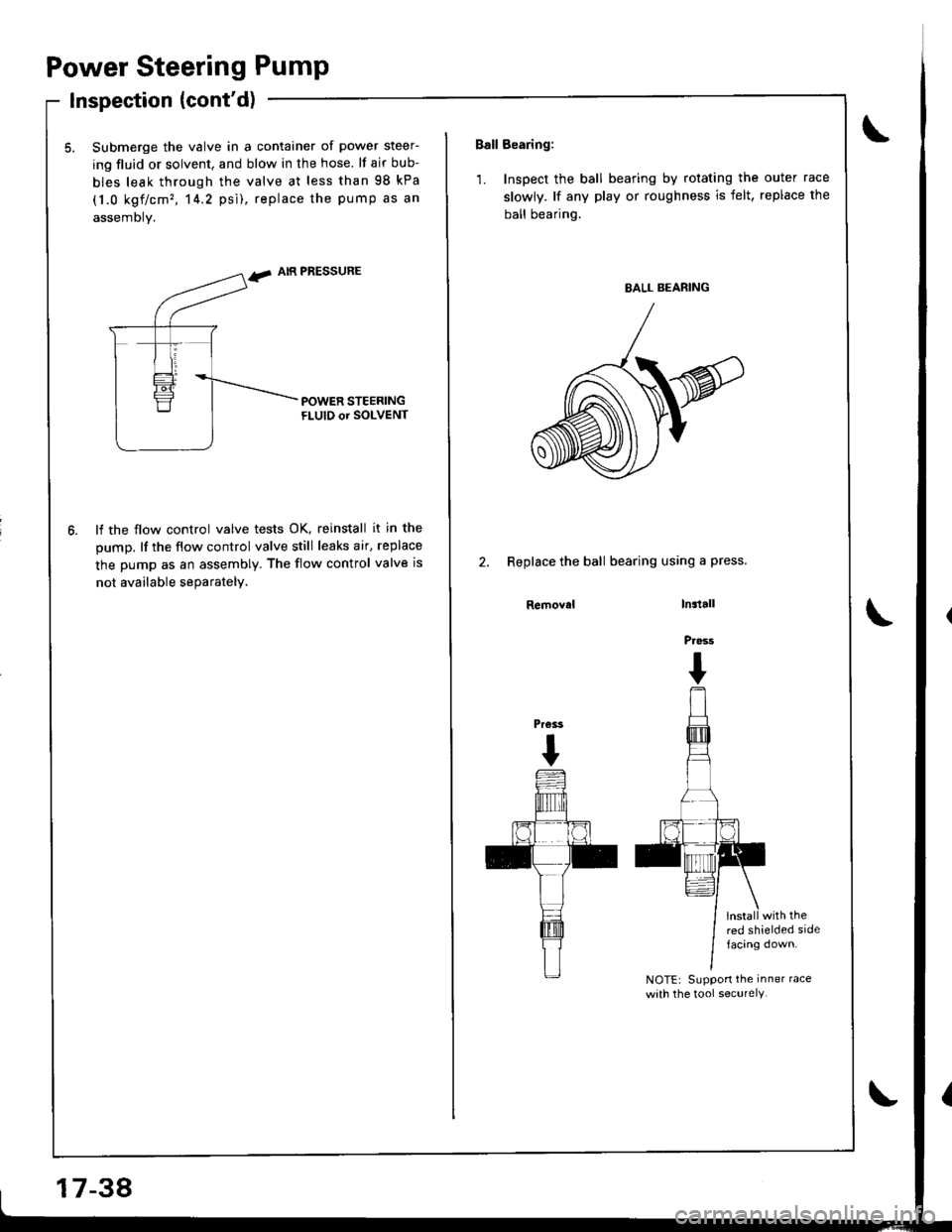
Power Steering Pump
lnspection {cont'd)
5. Submerge the valve in a container of power steer-
ing fluid or solvent, and blow in the hose. lf air bub-
bles leak through the valve at less than 98 kPa
(1.0 kgf/cm', 14.2 psi), replace the pump as an
assembly.
f. AIR PRESSURE
lf the flow control valve tests OK, reinstall it in the
pump. lf the flow control valve still leaks air, replace
the pump as an assembly. The flow control valve is
not available seDaratelv.
17-38
Ball Bearing:
1. Inspect the ball bearing by rotating the outer race
slowly. lf any play or roughness is felt, replace the
ball bearing.
2. Replace the ball bearing using a press.
Removalln3tall
Pross
I
install with thered shielded sidefacing down.
NOTEr Suppon the inner race
with the tool securelY.
Pr€ss
I
Page 689 of 1681
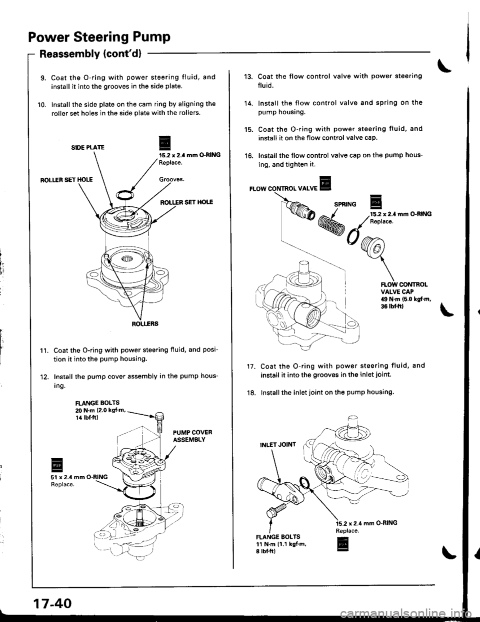
Power Steering Pump
9. Coat the O-ring with power steering fluid, and
install it into the grooves in the side plate.
10. Install the side plate on the cam ring by aligning the
roller set holes in the side plate with the rollers.
SIOE PLATEmrn O-RltlG
ROLI.ER SET HOLE
ROTT.ER SET HOTT
Coat the O-ring with power steering fluid, and posi-
tion it into the pumP housing.
Install the pump cover assembly in the pump hous-
Ing.
Reassembly (cont'dl
FLANGE BOLTS20 N.m 12.0 kgl m,
14 rbf.ftl
-
EI15.2 | 2.4Replace.
Groov6s,
iI
[,
1'�I.
I
17-40
14.
tc.
13. Coat the flow control valve with power steering
fluid.
Install the flow control valve and spring on the
pump housing.
Coat the O-ring with powet steering fluid, and
install it on the flow control valve cap.
Install the flow control valve cap on the pump hous-
ing. and tighten it.
FLOW CONTROL VALVE
n|m O-RING
SPRTNG E/-^-/ 215.2 x2.1
KWM ,// Reptace.
*o@ra
Y
l\i \
Coat the O-ring with power steering fluid, and
install it into the grooves in the inl€t joint.
Installthe inlet joint on the pump housing.
FLOW CONTROLVALVE CAP49 N'm (5.0 kgl.m,36 tbtft)
17.
18.
FLANGE BOLTS11 N.m 11.1 kgt.m,8 rbf.ftl
Replace.-
E
Page 690 of 1681
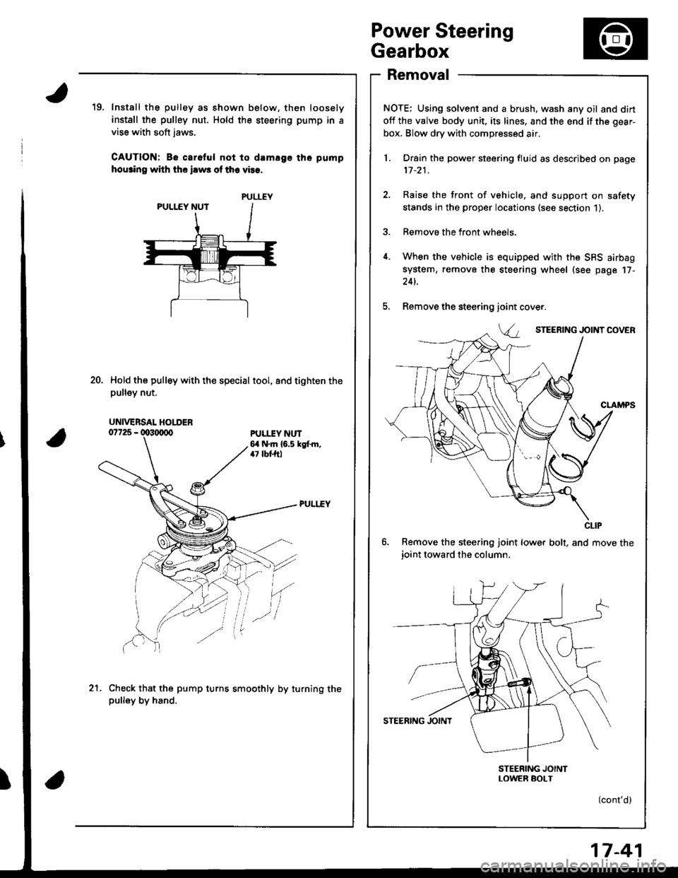
Power Steering
Gearbox
Removal
NOTE: Using solvent and a brush, wash any oil and dirt
off the valve body unit, its lines, and the end if the gear-
box. Blow dry with compressed air.
l. Drain the power steering fluid as described on page
11-21.
2. Raise the front of vehicle, and support on safety
stands in the proper locations (see section 1).
3. Remove the front wheels.
4. When the vehicle is equipped with the SBS airbag
system, remove the steering wheel (see page 17-
24t.
5. Remove the steering
6. Remove the steering joint lower bolt, and move the
ioint toward the column.
STEERING JOINTLOWER SOI-T
(cont'd)
19. Install the pulley as shown below, then loosely
install the pulley nut. Hold the steering pump in a
vise with soft jaws.
CAUTION: Be carelul not to damlge tho pump
hou3ino with ths ilws of th6 vies.
Hold the pulley with the special tool, and tighten thepu ey nut.
ioint
Va
20.
PULI.IY NUT6,1 N.m {6.5 kgt m,47 lbf,ftl
'(
Check that the pump turns smoothly by turning thepulley by hand.
.-l
21.
PULLEY
UNIVERSAL HOLDER
CLIP
17-41
Page 698 of 1681
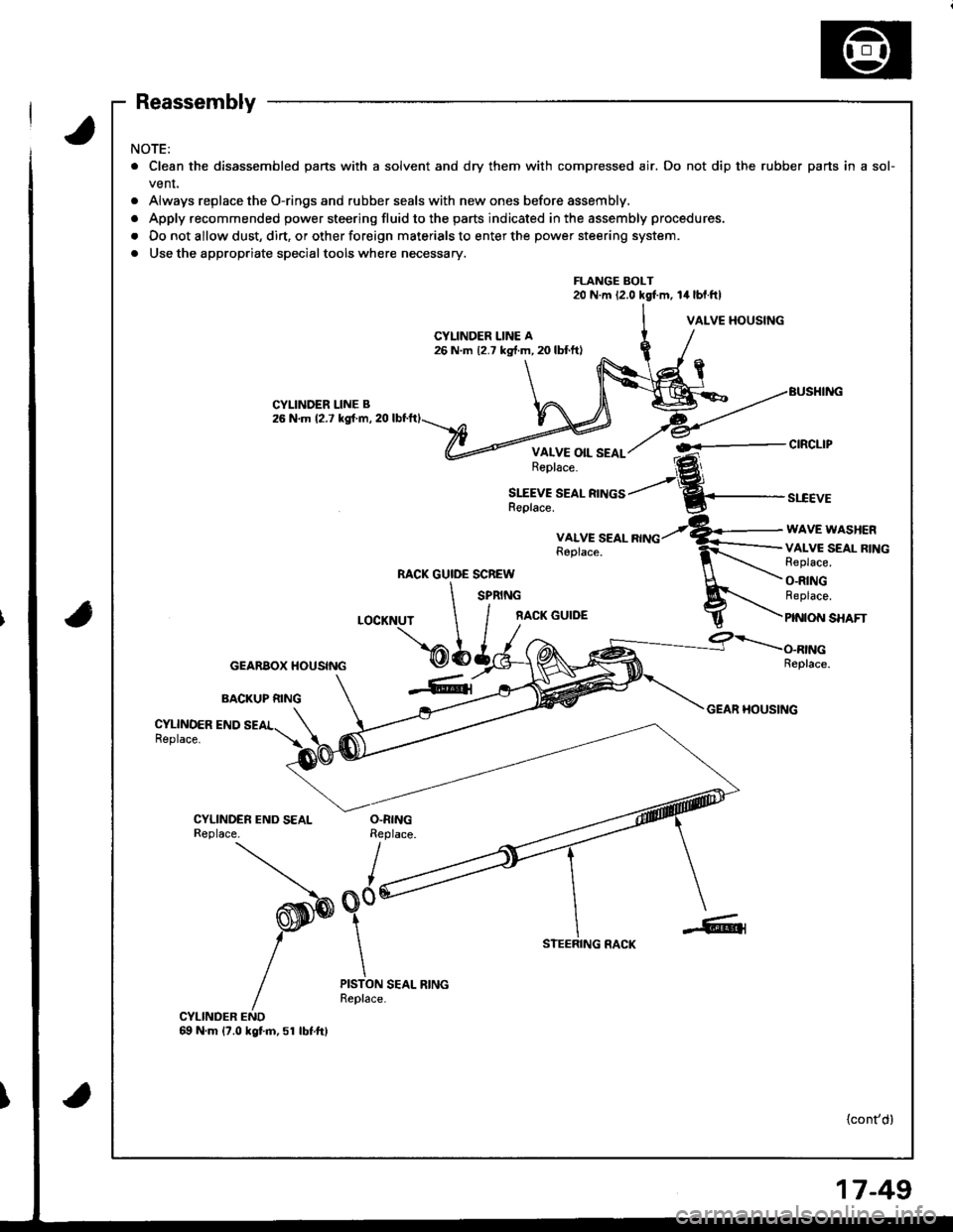
ra
NOTE:
. Clean the disassembled parts with a solvent and dry them with compressed air. Do not dip the rubber parts in a sol-
venr,
. Always replace the O-rings and rubber seals with new ones before assembly,
. Apply recommended power steering fluid to the parts indicated in the assembly procedures.
. Do not allow dust, dirt, or other foreign materials to enter the power steering system.
. Use the appropriate specialtools where necessary.
FLANGE BOLT20 N.m 12.0 kgf.m, 14 lbl.ftl
VALVE HOUSING
CYLINDER LINE B26 N.m 12.7 kgf.m, 20
VALVE OIL SEALReplace.
SLEEVE SEAL RINGSReplace.st"cEvE
VALVE SEALReplace.
WAVE WASHER
VALVC SEAL RINGReplace.
O-RINGReplace.
PINION SHAFT
RACK GUIDE SCREW
LOCKNUT \
cEARBoxHousrNc \b
SPRING
f,ACK GUIDE
BACKUP RING
Replace.
GEAR HOUSINGCYLINDER ENDReplace.
CYLINDER END SEALReplace.O.RINGReplace.
I
o0'
STEERING RACK
PISTON SEAL RINGReplace.
CYLINDER END69 N.m {7.0 kgtm,51 lbtftl
{cont'd}
Page 699 of 1681
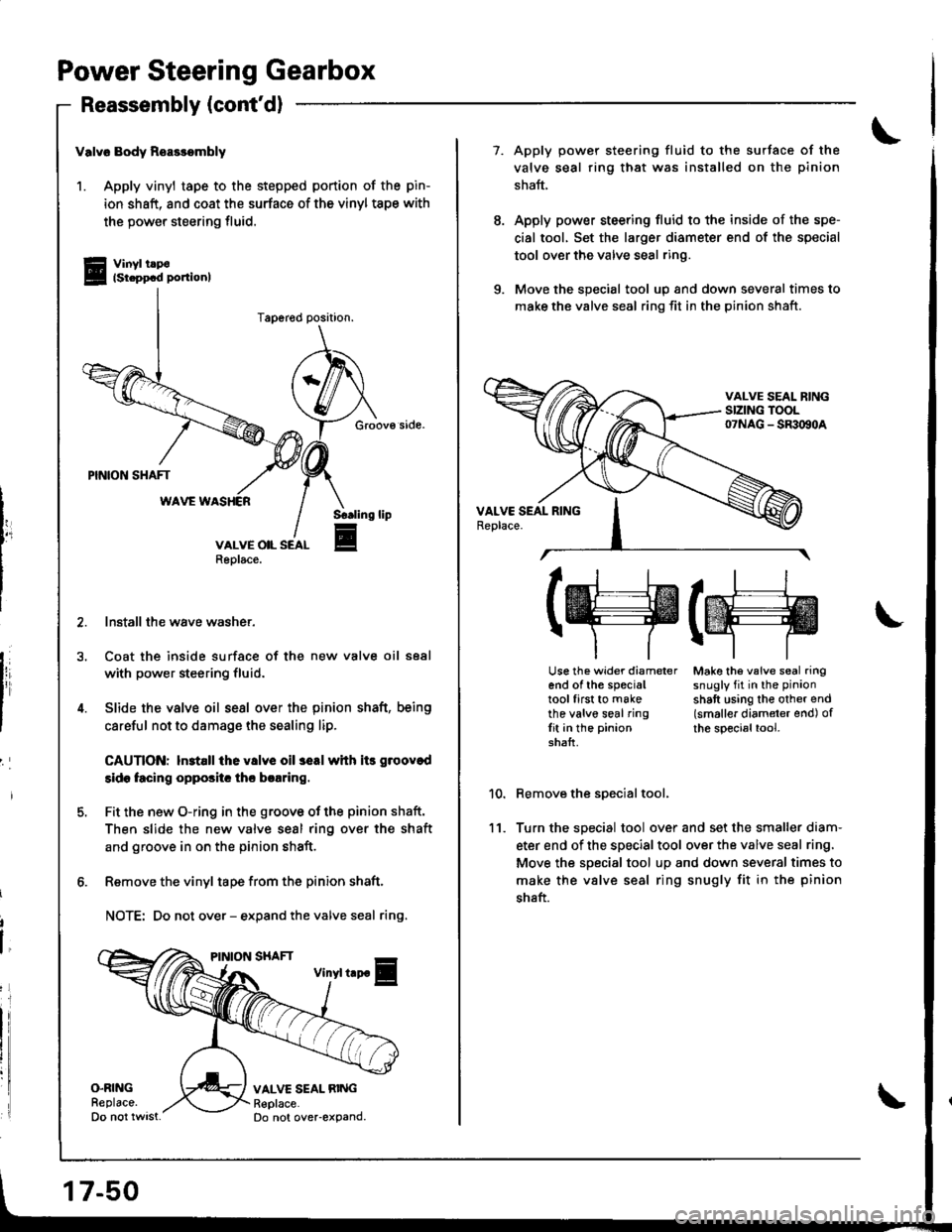
Power Steering Gearbox
Reassembly (cont'dl
i
valv6 Body Reasrombly
1. Apply vinyl tape to the stepped portion of the pin-
ion shaft, and coat the surface of the vinyl tspe with
the power steering fluid.
Vinyl tlp€lst.ppcd ponionl
Groov€ side.
Install the wave washer,
Coat the inside surface of the new valve oil seal
with power steering fluid.
Slide the valve oil sesl over the pinion shaft, being
careful not to damage the sealing lip.
CAUTIONT ln3tall the v8lve oil 3eal whh itr groovod
side facing oppositc thc braring.
Fit the new O-ring in the groovo of the pinion shaft.
Then slide the new valve sesl ring over the shaft
and groove in on the pinion shaft.
Remove the vinyl tape from the pinion shaft.
NOTE: Do not over - expand the valve seal ring.
Sr.lino
E
lip
VALVE SEAL RINGReplace.Do not over-expand.
17-50
7. Apply power steering fluid to the surJace of the
valve seal ring that was installed on the pinion
shaft,
Apply power steering fluid to the inside of the spe-
cial tool, Set the larger diameter end of the special
tool over the valve seal ring.
Move the sDecial tool uo and down several times to
make the valve seal ring fit in the pinion shaft.
11.
(w(ffi \
Use the wider diameter Make th6 valve seal ringend of the special snugly fit in the pinion
tool first to make shaft using the other endthe valve seal ring (smaller diameter end) ofIit in the pinion the special tool.shalt.
Remove the special tool,
Turn the special tool over and set the smaller diam-
eter end of the special tool over the valve seal ring,
Move the special tool up and down several times to
make the vslve seal ring snugly fit in the pinion
shaft.
Page 700 of 1681
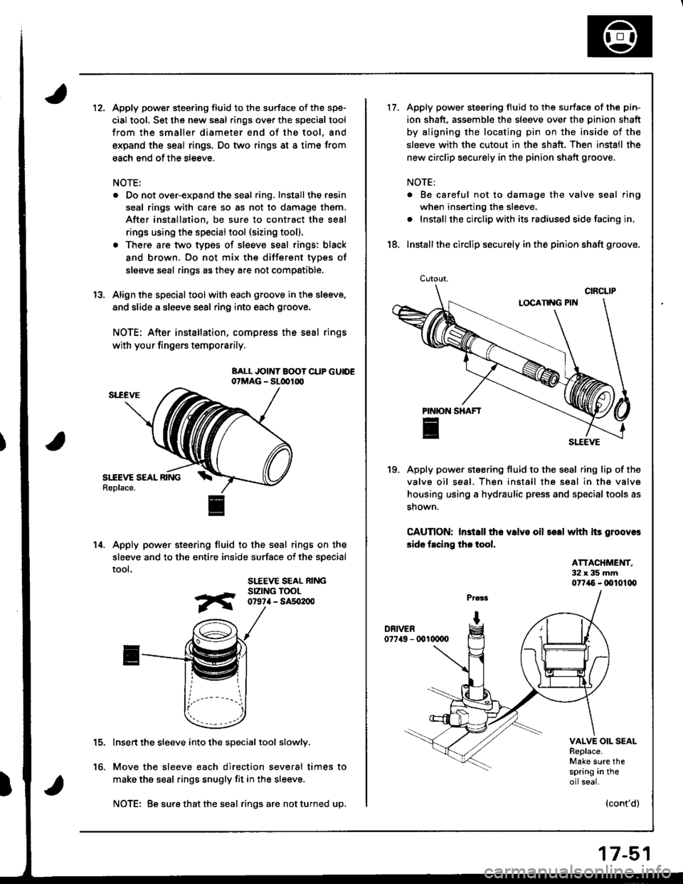
12.Apply power steering fluid to the surface of the spe-
cial tool. Set the new seal rings over the special tool
from the smaller diameter end of the tool, and
expand the seal rings. Do two rings at a time from
each end of the sleeve.
NOTE:
. Do not over-expand the seal ring. Install the resin
seal rings with care so as not to damage them.
After installation, be sure to contract the seal
rings using the specialtool (sizing tool).
. There are two types of sleeve seal rings: black
and brown. Oo not mix the different types of
sleeve seal rings as they are not compstible.
Align the special toolwith each groove in the sleeve.
and slide a sleeve seal ring into each groove.
NOTE: After installation, compress the seal rings
with your fingers temporarily.
BALL JOINT B(X)? CUP GUIDE07MAG - SLdrlrx,
Apply power steering fluid to the seal rings on the
sleeve and to the entire inside surface of the soecial
tool.
SLEEVE SEAL NINGSIZING TOOL0r9?a - sat02n0
Insert the sleeve into the special tool slowly.
Move the sleeve each direction several times to
make the seal rings snugly fit in the sleeve.
NOTE: Be sure that the seal ringsare notturned up.
13.
14.
to.
17-51
Cutout.
17.Apply power steering fluid to the surface of the pin-
ion shaft, assemble the sleeve over the pinion shaft
by aligning the locating pin on the inside of the
sleeve with the cutout in the shaft. Then install the
new circlip securely in the pinion shaft groove.
NOTE:
. Be careful not to damage the valve seal ring
when inserting the sleeve.
. Install the circlip with its radiused side facing in,
18. Installthe circlip securely in the pinion shaft groove.
Apply power steering fluid to the seal ring lip of the
valve oil seal. Then install the seal in the valve
housing using a hydraulic press and special tools as
snown.
CAUnON: Instsll tho valvo oil s€.| with its groovcs
side facing th. tool.
19.
ATTACHMET{T,32x35mm077i15 - (xll01lX,
VALVE OIL SEALReplace.Make sure thespring in theoilseal.
(cont'd)
Page 701 of 1681
Power Steering Gearbox
Reassembly (cont'dl
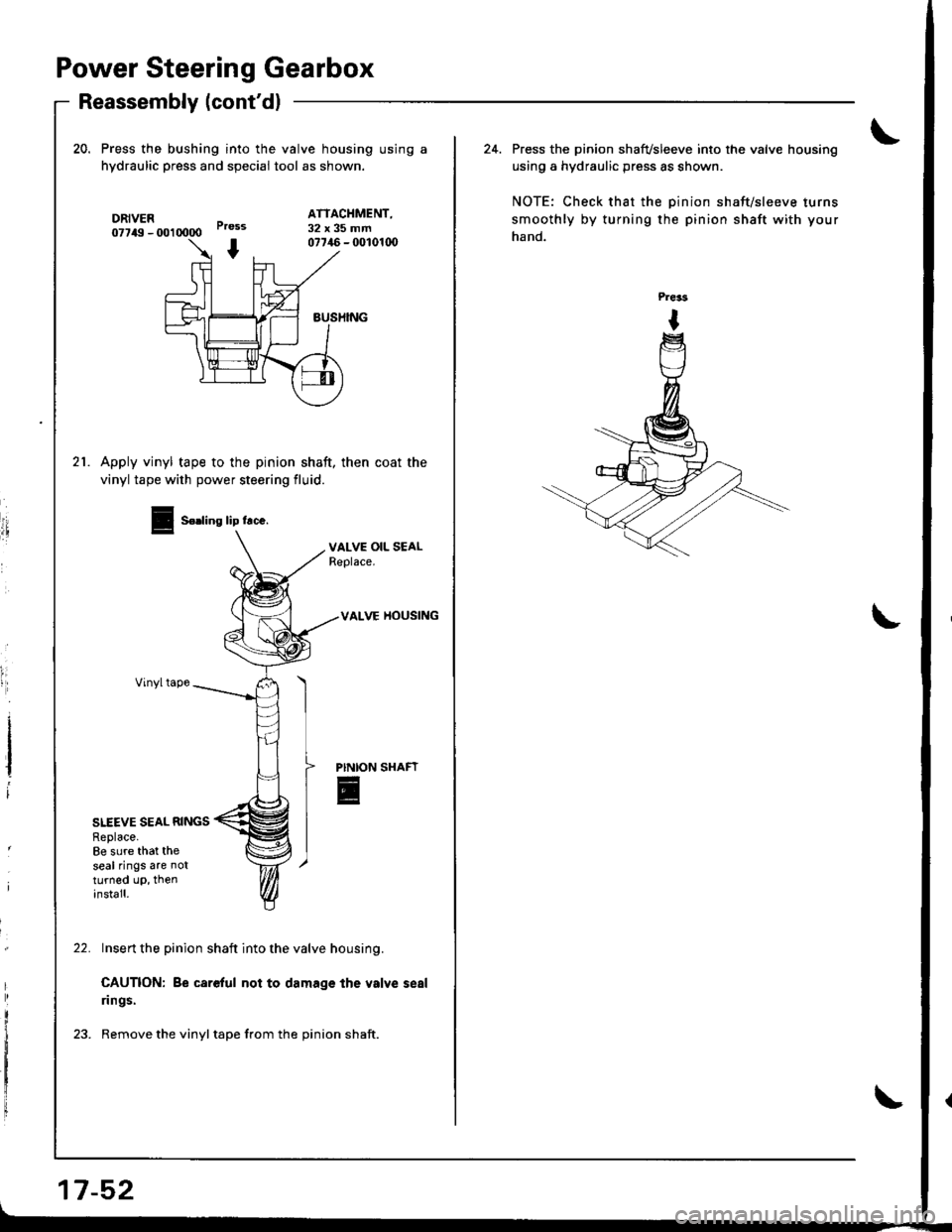
20. Press the bushing into the valve housing using a
hydraulic press and speciai tool as shown.
DRIVER07749 - U)l 0000
ATTACHMENT,32x35mmPress
I07746 - fi)l01(x)
sUSHING
21.Apply vinyl tape to the pinion shaft, then coat the
vinyl tape with power steering fluid.
I
i
I
VALVE OIL SEALReplace.
VALVE HOUSING
Vinyltape
PINION
E
SITEVE SEAL RINGSReplace.8e sure that theseal rings are notturned up, theninstall.
Insert the pinion shaft into the valve housing.
CAUTION: Be careful not to damage the valve seal
rings.
Remove the vinyl tape from the pinion shaft.
Seding lip lrce.
17-52
24. Press the pi.ion shafvsleeve into the valve housing
using a hydraulic press as shown.
NOTE: Check that the pinion shaft/sleeve turns
smoothly by turning the pinion shaft with your
hand.