Timing HONDA INTEGRA 1998 4.G Owner's Guide
[x] Cancel search | Manufacturer: HONDA, Model Year: 1998, Model line: INTEGRA, Model: HONDA INTEGRA 1998 4.GPages: 1681, PDF Size: 54.22 MB
Page 1058 of 1681
J
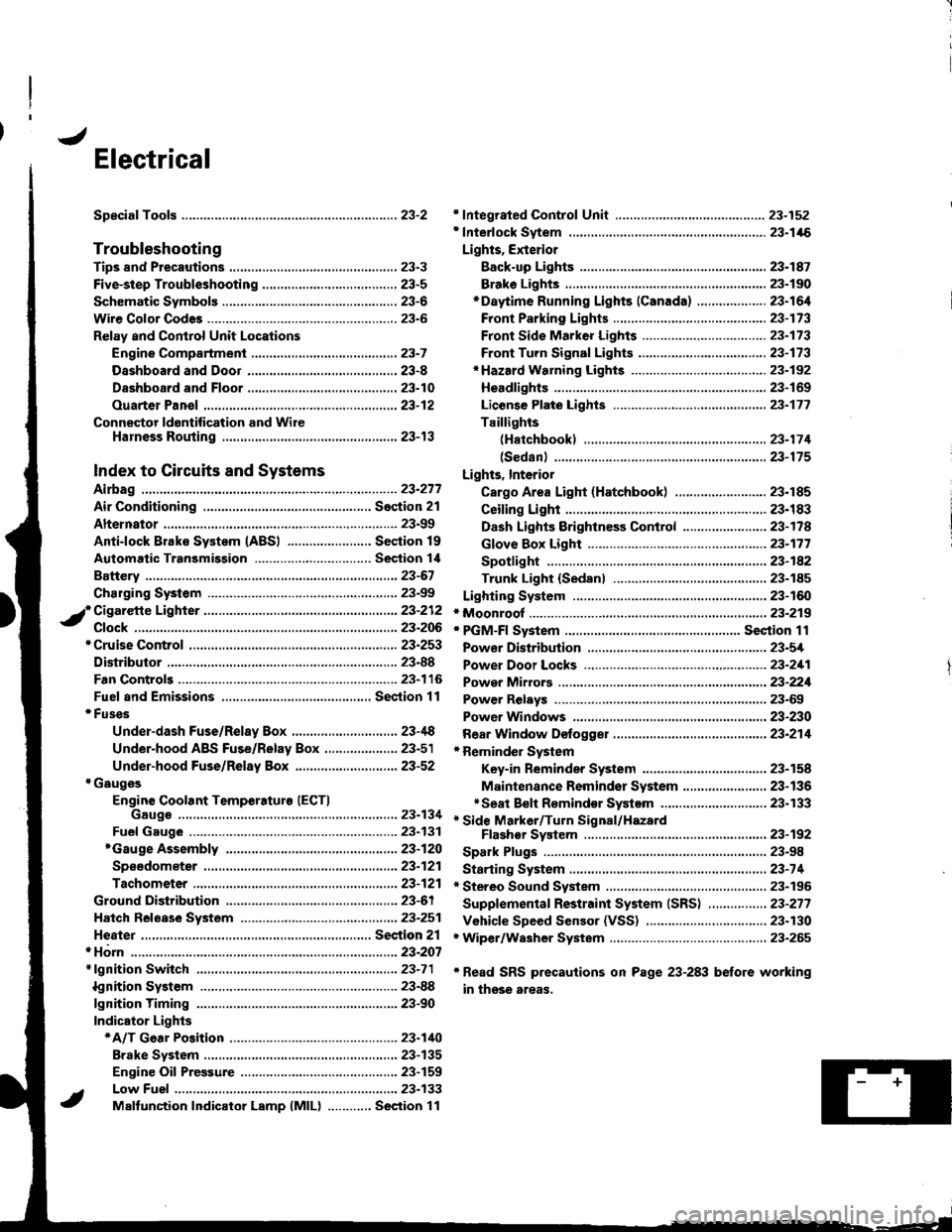
Electrical
Speciaf Toofs ..........................23-2
Troubleshooting
Tips 8nd Precautions .......................,..,.,.,.,.,......,..., 23-3
Five-step Troubleshooting ............,......,.,.,...,..,....., 23-5
Schsmatic Svmbols ...............23-6
Wire Color Code3 .. ................. 23-6
Relay and Control Unit Locations
Engine Compartment ......,.,.................,.,.,.,.,.,,,, 23-7
Dashboard and Door .........,...........,.....,.,....,.,.... 23-8
Dashboard and Floor ......................................... 23-10
Ouarter Pan€f .,,.,...,.,..,...,,,23-12
Connector ldontification and WireHarness Routing ......,.,......23-'13
Index to Circuits and Systems
Airbag
* Integrated Control Unit .....,.,.,.....23-152* Interlock Sytem .,...,.,...........,. 23.146
Lights, Exterior
Eack-up LighB ..................23.187
Brake Ligh$ ......................23-190*Daytime Running Lights (Canada) ................... 23"164
Front Parking Lights .......................................... 23-173
Front Side Marker Lights .................................. 23-173
Front Turn Signal Lights ..................-.......,...,.,. 23-173* Hazard Warning Lights ....................,........,....... 23-192
Headlights.....23-169
23-253 powerDistribution..................... 23-5/r
Air Conditioning.....,....... Soction 21
Alternator ..........,................... 23.99
iCigarette Lighter .........23-212
*Cruise Control
Distributor
'.'.,.'.'.,.'...,,,,.,''.'.,.',.'''.' 23.277
.............................. 23.88
................... 23-90lgnition Timing ......
Indicator Lights
Key-in Reminder System
Maintenance Reminder System*Seat Belt R€mindor System .,...........................* Side Marker/Turn Signal/HazardFlashcr Svstem .................23-192
Spark Plugs ............................23-98
Starting System .....................23-74* Stereo Sound System ...,......,..........,...,......,.,.,.,..,., 23-196
Supplemental Restraint System (SRS) ................ 23-277
Vshicle Speed Sensor (VSS) ................................. 23.130r Wiper/Washer System .........................................., 23-265
*Read SRS precautions on Psge 23-283 before working
in those areas,
23-154
23.136
23"133
Page 1155 of 1681
lgnition System
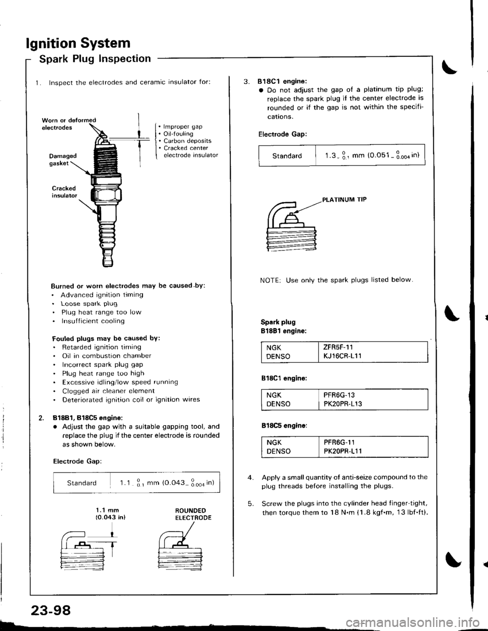
1. Inspect the electrodes and ceramic insulator for:
Spark Plug lnspection
. lmproper gap. Oil-fouling. Carbon deposits. Cracked centerelectrode insulatorDamagedgaskei
Burned or worn electrodes may be caused by:
. Advanced ignition timing. Loose spark plug
. Plug heat range too low. Insufficient cooling
Fouled plugs may be caused bY:. Retarded ignition liming. Oil in combustion chamber. Incorrect spark plug gap
. Plug heat range too high. Excessive rdling'low speed running
. Clogged air cleaner element. Deteriorated ignition coil or ignition wires
81881, 818C5 engine:
. Adjust the gap wjth a suitable gapping tool, and
replace the plug if the center electrode is rounded
as shown below.
Electrode Gap:
Standard 'l .1 ; r mm {0.043 ; ooa in)
E.
23-98
3.818C1 engine:
a Do not adjust the gap ol a platinum tip plug;
replace the spark plug it the center electrode is
rounded or if the gap is not within the specifi-
cattons.
Electrode Gap:
Standard I t.s-3., mm (0.051-3.oo4in)
5.
PLATINUM TIP
NOTE: Use onlv the spark plugs listed below
Spark plug
Bl88l engine:
NGK I ZFR5F-11
DENSO I KJ 16CR-111
818C1 engine:
NGK PFR6G-13
DENSO I PK2OPR-113
818C5 engine:
NGK PFR6G-I1
DENSO PK2OPR-111
Apply a small quantity ot anti-seize compound to the
plug threads belore installing the plugs.
Screw the plugs into the cylinder head tinger tight,
then torque them to 18 N.m (1 .8 kgf.m, 13lbf.ft).
Page 1642 of 1681
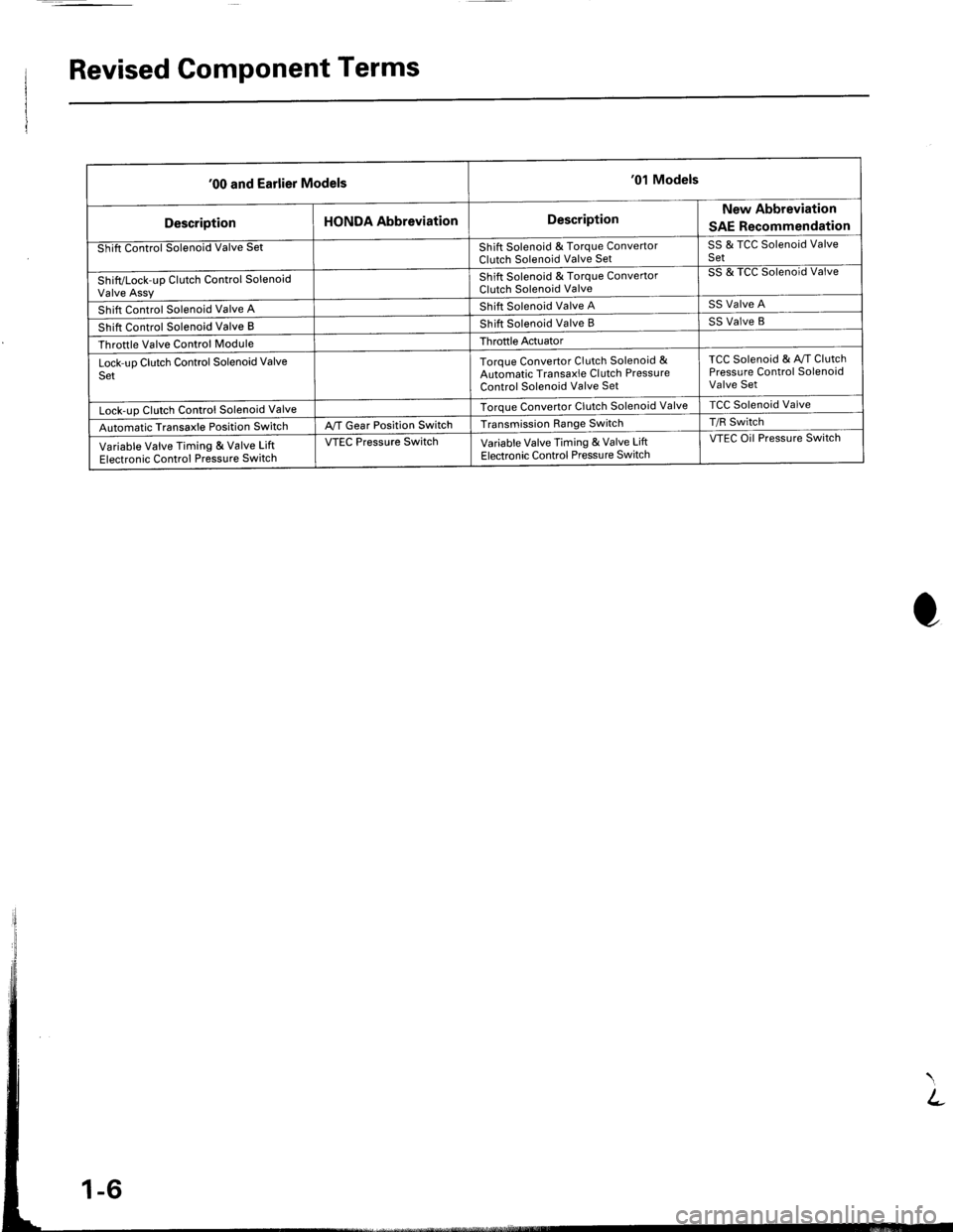
Revised Component Terms
'00 and Earlier Models'01 Models
DescriptionHONDA AbbreviationDescriptionNew Abbreviation
SAE Recommendation
Shift Control Solenoid Valve SetShift Solenoid & Torque ConvertorClutch Solenoid Valve SetSS & TCC Solenoid ValveSet
Shift/Lock-up Clutch Control SolenoidValve Assy
Shift Solenoid & Torque ConvertorClutch Solenoid Valve
SS & TCC Solenoid Valve
Shift Control Solenoid Valve AShift Solenoid Valve ASS Valve A
Shift Control Solenoid Valve BShift Solenoid Valve BSS Valve B
Throttle Valve Control ModuleThroftle Actuator
Lock-uo Clutch Control Solenoid ValveSetToroue Convertor Clutch Solenoid &Automatic Transaxle Cl utch PressureControl Solenoid Valve Set
TCC Solenoid & Av/T ClutchPressure Control SolenoidValve Set
Lock-uo Clutch Control Solenoid ValveTorque Convertor Clutch Solenoid ValveTCC Solenoid Valve
Automatic Transaxle Position SwitchA,/T Gear Position SwitchTransmission Range SwitchT/R Switch
Variable Valve Timing & Valve LiftElectronic Control Pressure Switch
VTEC Pressure SwitchVariable Valve Timing & Valve LiftElectronic Control Pressu re Switch
VTEC Oil Pressure Switch
Page 1654 of 1681
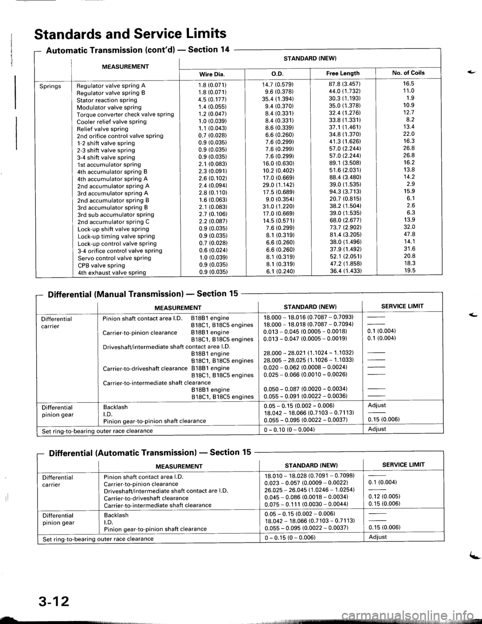
MFASIIREMENTSTANDARD (NEW}
Wire Dia.o.D.Free LengthNo. of Goils
SpringsRegulator valve spring ARegulator valve spring BStator reaction sPringModulator valve springTorque converter check valve springCooler relief valve springRelief valve spring2nd orifice control valve spring1-2 shift valve spring2-3 shift valve spring3-4 shift valve spring1st accumulator spring4th accumulator spring B4th accumulator spring A2nd accumulator spring A3rd accumulator spring A2nd accumulator spring B3rd accumulator spring B3rd sub accumulator spring2nd accumulator spring CLock-up shift valve springLock-up timing valve springLock-up control valve spring3-4 orifice control valve springServo control valve springCPB valve spring4th exhaust valve spring
1.8 (0.071)
1.8 (0.071)
4.5 rc.177].1.4 (0.05s)
1.2 10.047l.1.0 (0.039)
1.1 (0.043)
0.7 (0.0281
0.9 (0.035)
0.9 (0.035)
0.9 (0.035)
2.1 (0.083)
2.3 (0.091)
2.6 (0.102)
2.4 (0.094)
2.8 (0.110)
1.6 (0.063)
2.1 (0.083)
2.7 (0.106)
2.2 l0.o87l0.9 (0.035)
0.9 (0.035)
0.7 (0.028)
0.6 (0.024)
1.0 (0.039)
0.9 (0.0351
0.9 (0.035)
14.7 (0.5791
9.6 (0.378)
35.4 (1 .394)9.4 (0.370)
8.4 (0.331)
8.4 (0.331)
8.6 (0.339)
6.6 (0.260)
7.6 (0.299)
7.6 (0.299)
7.6 (0.299)
16.0 (0.630)
10.2 rc.402117.0 (0.669)
29.0 11.142117.5 (0.689)
9.0 (0.354)
31.0 (1 .220)17.0 (0.669)
14.5 (0.571)
7.6 (0.299)
8.1 (0.319)
6.6 (0.260)
6.6 (0.260)
8.1 (0.319)
8.1 (0.319)
6.1 (0.240)
87.8 (3.457)
44.0 (1.732\
30.3 (1.193)
35.0 (1.378)
32.4 (1.2761.
33.8 (1.331)
37.1 (1.461)
34.8 (1.370)
41.3 (1.626)
57.0 12.244157.0 12.244].89.1 (3.508)
s1.6 (2.0311
88.4 (3.480)
39.0 (1 .53s)94.3 (3.713)
20.7 (0.815)
38.2 (1.504)
39.0 (1.535)
68.0 (2.677)
73.7 (2.9021
81.4 (3.205)
38.0 (1.496)
37.9 (1.492)
52.1 (2.0511
47.2 (1 .858)36.4 (1.433)
16.51 1.01.910.912.78.213.422.01A ?
26.826.8't6.2
13.814.2z.J15.9o. l2.66.313.932.O47.814.1?1 A
20.8ttJ.JI v.5
Standards and Service Limits
Automatic Transmission (cont'd) - Section 14
Differential (Manual Transmission) - Section 15
Differential (Automatic Transmission) - Section 15
ilt5stlrrr, - 4,
MEASUREMENTSTANDARD (NEW}SERVICE LIMIT
Differentialca rnerPinion shaft contact area l.D. 81881 engineB18C1, 818C5 engines
Carrier-to-pinionclearance Bl88lengine818C1, 818C5 enginesDriveshafVintermediate shaft contact area l.D.81881 engine818C1. 818C5 engines
Carrier-to-driveshaft clearance 81881 engine818C1, 818C5 engines
Carrier-to-intermediate shaft clea rance81881 engine818C1, 818C5 engines
18.000 - 18.016 (0.7087 - 0.7093)18.000 - 18.018 (0.7087 - 0.7094)0.013 - 0.045 (0.0005 - 0.0018)0.013 - 0.047 (0.0005 - 0.0019)
28.000 - 28.021 11.1024 - 1.1032].28.005 - 28.025 l1 .'�t026 - 1 .1 033)
0.020 - 0.062 (0.0008 - 0.0024)0.025 - 0.066 (0.0010 - 0.00261
0.050 - 0.087 (0.0020 - 0.0034)0.055 - 0.091 (0.0022 - 0.0036)
- toooot0.1 (0.004)
Differentialpinion gearBacklasht.D.Pinion gear-to-pinion shaft clearance
0.05 - 0.15 (0.002 - 0.006)18.042 - 18.066 (0.7103 - 0.71 1 3)0.055 - 0.095 (0.0022 - 0.0037)
Adjust
0.15 (0.006)
Set ring-to-bearing)uter race clearance0 - 0.10 (0 - 0.004)Adjust
nsmlssaonl - Sectton
MEASUREMENTSERVICE LIMITSTANDARD (NEW}
Differentialca rrierPinion shaft contact area l.D.Carrier-to-pinion clearanceDriveshaft/i ntermediate shaft contact are l.D.
Carrier-to-driveshaft clearanceCarrier-to-intermediate shaft clearance
18.010 - 18.028 (0.7091 - 0.7098)0.023 - 0.057 (0.0009 - 0.0022)26.025 - 26.045 11.0246 - 1.02541
0.045 - 0.086 (0.0018 - 0.0034)0.075 - 0.1 11 (0.0030 - 0.0044)
0.1 (0.004)
0.12 (0.005)
0.15 (0.006)
Differentialpinion gearBacklasht.D.Pinion gear-to-pinion shaft clearance
0.05 - 0.15 (0.002 - 0.006)18.042 - 18.066 (0.7 103 - 0.71 1 3)0.055 - 0.095 (0.0022 - 0.0037)0.15 (0.006)
Set ring-to-bearing outer race clearance0 - 0.15 (0 - 0.006)Adiust
uL-
3-12
(-
Page 1656 of 1681
ng
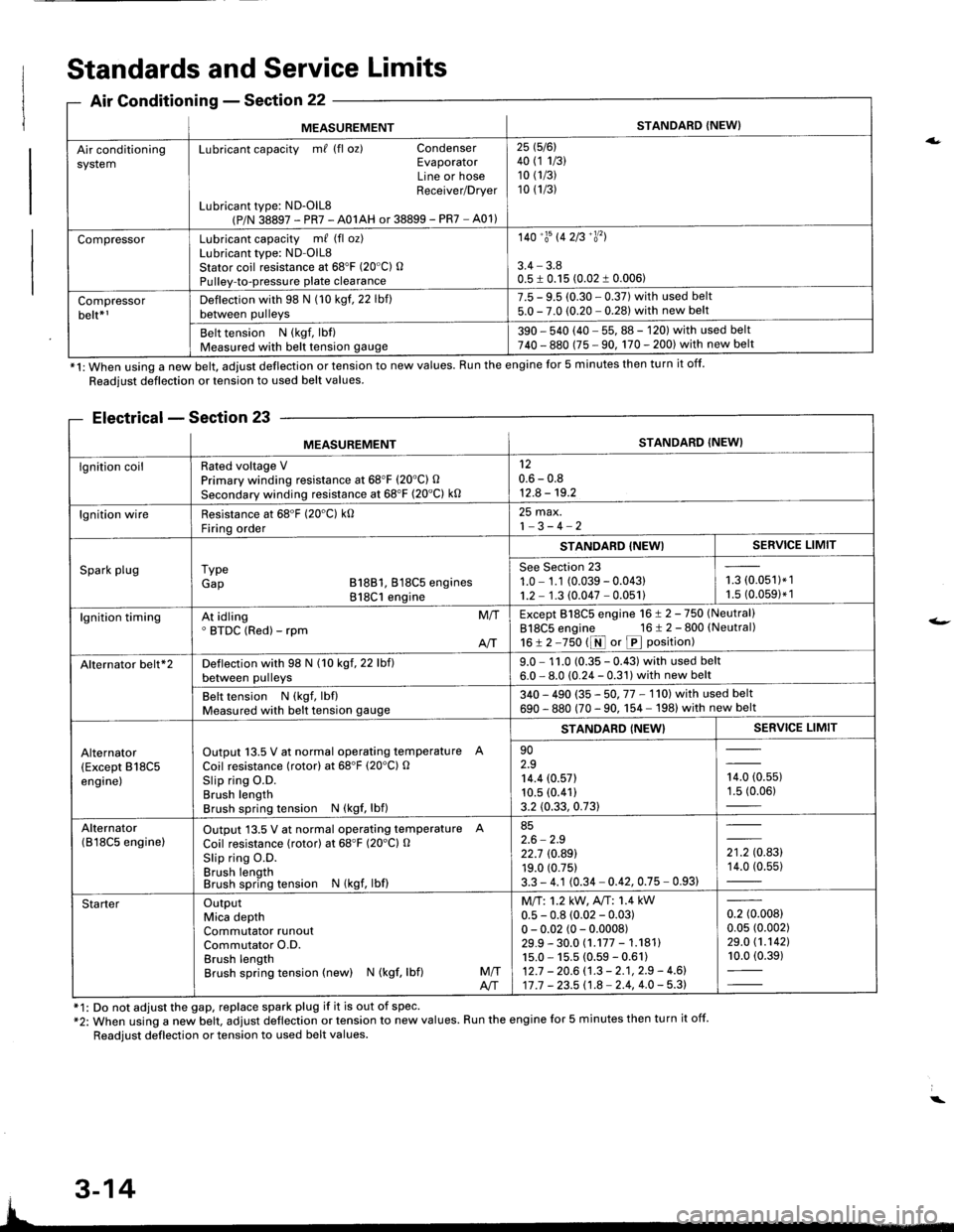
MEASUREMENTSTANDARD {NEW}
Air conditioningsystemLubricant capacity m/ (fl oz) CondenserEvaporatorLine or hoseReceiver/Drver
Lubricant type: ND-OlL8(P/N 38897 - PR7 - A01AH or 38899 - PR7 - A01)
25 1516l40 (1 1/3)10 (1/3)
10 (1/3)
CompressorLubricant capacity m/ (fl oz)Lubricant type: ND-OlL8Stator coil resistance at 68'F (20"C) OPulley-to-pressure plate clearance
140'�trs 142B'�y'�l
3.4 - 3.80.5 I 0.15 (0.02 1 0.006)
Compressorbelt*rDeflection with 98 N (10 kgf. 22 lbf)between pulleys
7.5 - 9.5 (0.30 - 0.37) with used belt5.0 - 7.0 (0.20 - 0.281 with new belt
Belt tension N (kgf, lbf)Measured with belt tension gauge390 - 540 (40 - 55, 88 - 120) with used belt740 - 880 (75 - 90, 170 - 200) with new belt
*1: When using a new belt, adjust deflection or tension to new values. Run the engine for 5 minutes then turn it off.
Standards and Service Limits
Air Conditionins - Section 22
Readjust deflection or tension to used belt values.
Electrical - Section 23
f1: Do not adjust the gap, replace spark plug if it is out of spec'*2: When using a new belt. adjust deflection or tension to new values. Run the engine for 5 minutes then turn it off.
Readjust deflection or tension to used belt values.
a.
t-
MEASUREMENTSTANDARD (NEW}
lgnition coilRated voltage VPrimary winding resistance at 68"F (20'C) O
Secondary winding resistance at 68'F (20"C) k0
120.6 - 0.812.8 - 19.2
lgnition wireResistance at 68'F (20'C) k0Firinq order
25 max.1-3-4-2
Spark plugI ypeGap B18B1, 818C5 engines818C1 engine
STANDABD {NEWISERVICE LIMIT
See Section 231.0 - 1.1 (0.039 - 0.04311.2 - 1.3 (0.047 - 0.051)i-= roru',t.',1.5 (0.0591* 1
lgnition timingAt idling' BTDC (Red) - rpmM/T
AIT
Except 818C5 engine 16 ! 2 -750 (Neutral)
818C5 engine 16 t 2 - 800 (Neutral)
16!2-750 t1r{ or p position)
Alternator belt*2Deflection with 98 N (10 kgf, 22 lbf)between pulleys9.0 - 1 1.0 (0.35 - 0.43) with used belt6.0 - 8.0 (0.24 - 0.31) with new belt
Belt tension N (kgf, lbflMeasured with belt tension gauge340 - 490 (35 - 50. 77 - 1'l0l with used belt
690 - 880 (70 - 90. 1 54 - 198) with new belt
Alternator(Except B18C5engine)
Output 13.5 V at normal operating temperature A
Coil resistance (rotor) at 68'F (20'C) OSlip ring O.D.Brush lengthBrush spring tension N (kgf, lbf)
STANDARD {NEW}SERVICE LIMIT
902.914.4 (0.571
10.5 (0.41)
3.2 (0.33, 0.73)
,0, to.uur1.5 (0.06)
Alternator(B l8C5 enginelOutput 13.5 V at normal operating temperature A
Coil resistance (rotor) at 68"F (20'Cl O
Slip ring O.D.Brush lengthBrush spring tension N (kgf, lbf)
852.6 - 2.922.7 rc.89119.0 (0.75)
3.3 - 4.1 (0.34 - 0.42, 0.75 - 0.93)
',to.tg14.0 (0.55)
StarterOutputMica depthCommutator runoutCommutator O.D.Brush lengthBrush spring tension (new) N (kgf, lbf)M/TA/T
Mll:1.2 kW, A"rT: 1.4 kW0.5 - 0.8 (0.02 - 0.03)0 - 0.02 (0 - 0.0008)29.9 - 30.0 (.177 - 1.18111s.0 - 15.5 (0.59 - 0.61)12.7 - 20.6 (.3 - 2.1, 2.9 - 4.6)17 .7 - 23.5 11.8 - 2.4, 4.0 - 5.3)
0.2 (0.008)
0.05 (0.002)
29.0 (1.1421
10.0 (0.39)
3-14