Timing HONDA INTEGRA 1998 4.G Owner's Manual
[x] Cancel search | Manufacturer: HONDA, Model Year: 1998, Model line: INTEGRA, Model: HONDA INTEGRA 1998 4.GPages: 1681, PDF Size: 54.22 MB
Page 441 of 1681
Description
Hydraulic Control (cont'd)
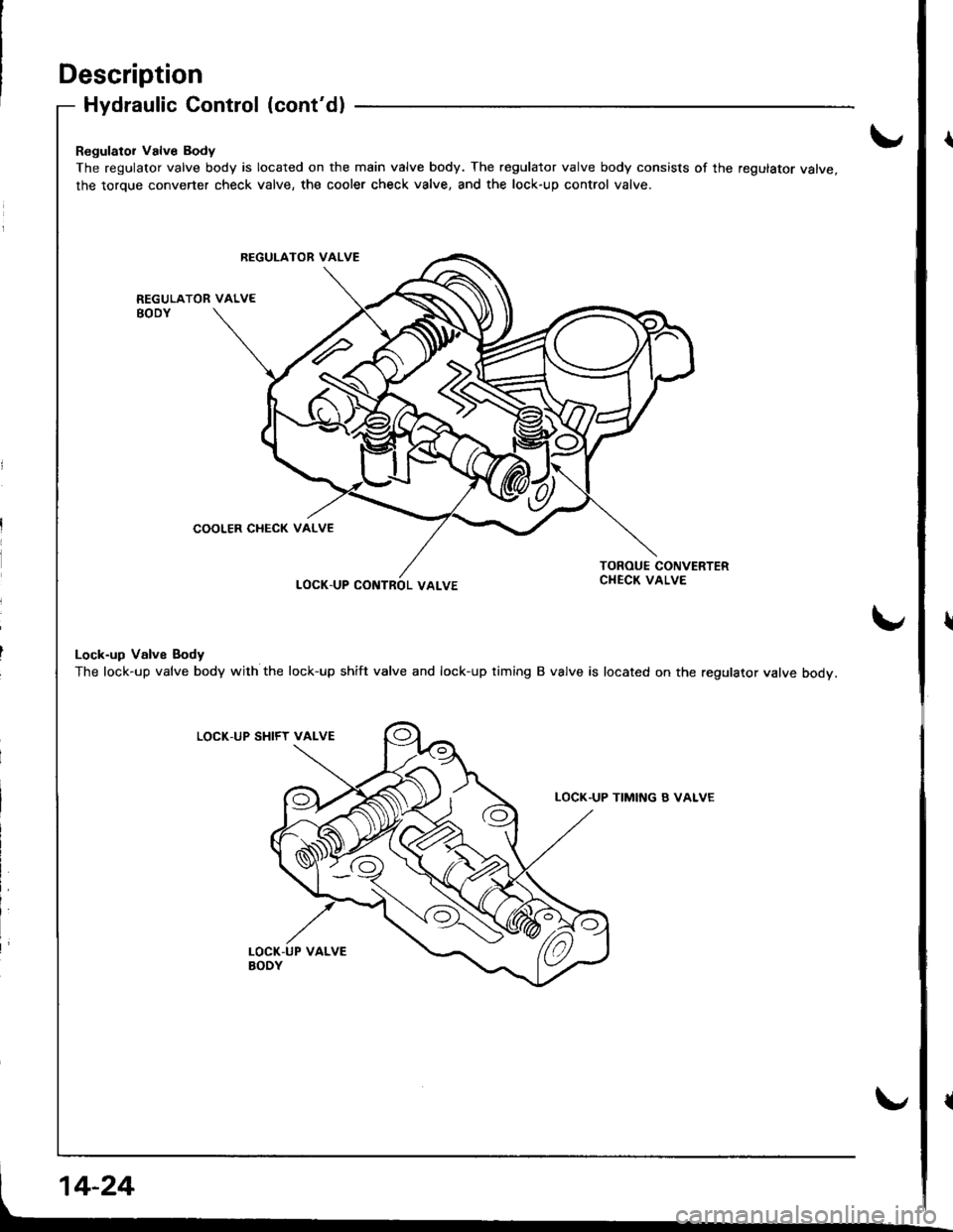
Regulator Valve Body
The regulator valve body is located on the main valve body. The regulator valve body consists of the regulator valve,
the torque converter check valve, the cooler check valve, and the lock-up control valve.
LOCK.UP CONTROL VALVE
Lock-up Valve Body
The lock-up valve body with the lock-up shift valve and lock-up timing B valve is located on the regulator valve body.
LOCK-UP SHIFY VALVE
TIMI[\'G B VALVE
REGUI-ATOR VALVE
COOLER CHECK VALVE
Page 456 of 1681
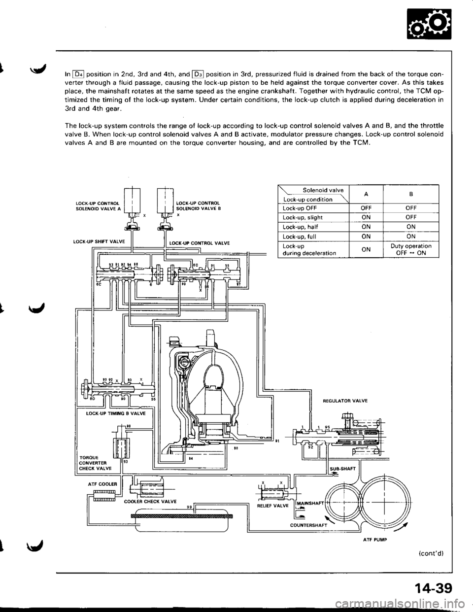
In E position in 2nd, 3rd and 4th, and E position in 3rd, pressurized fluid is drained from rhe back of the torque con-
verter through a fluid passage, causing the lock-up piston to be held against the torque converter cover. As this takes
place, the mainshaft rotates at the same speed as the engine crankshatt. Together with hydraulic control, the TCM op-
timized the timing of the lock-up system. Under certain conditions, the lock-up clutch is applied during deceleration in
3rd and 4th gear.
The lock-up system controls the range of lock-up according to lock-up control solenoid valves A and B, and the throttle
valve B. When lock-up control solenoid valves A and B activate, modulator pressure changes. Lock-up control solenoid
valves A and B are mounted on the torque converter housing. and are controlled by the TCM.
LOCK,UP CONTROL
LOCT.UP SHIfT VALVE
AlF COOIER
tocK uP coNTno! valvE
Solenoid valve
L*r""r "o.Jtio" \B
Lock'up OFFOFFOFF
Lock-up, slightONOFF
Lock-up, halfONON
Lock-up, fullONON
LOCK-Updu.ing decelerationONDuty operationOFF - ON
IOCK UP TIMING B VATVE
(cont'd)
14-39
Page 457 of 1681
Description
LOC(,UP SlllFT VATVE
Lock-up System (cont'd)
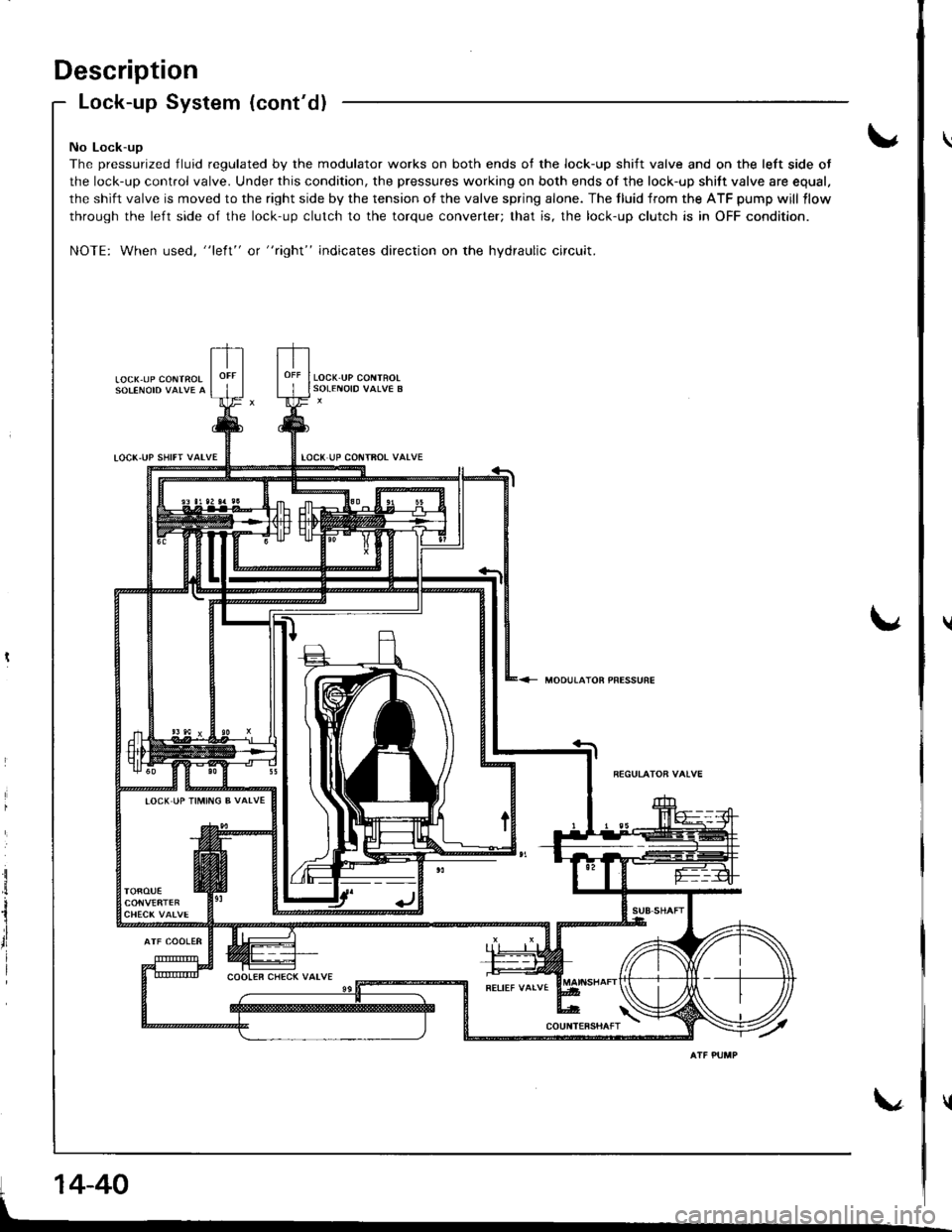
No Lock-ug
The pressurized fluid regulated by the modulator works on both ends of the lock-up shift valve and on the left side ot
the lock-up control valve. Under this condition, the pressures working on both ends of the lock-up shift valve are equal.
the shift valve is moved to the right side by the tension of the valve spring alone. The tluid from the ATF pump will llow
through the left side of the lock-up clutch to the torque converter; that is, the lock-up clutch is in OFF condition.
NOTE: When used, "left" or "right" indicates direction on the hydraulic circuit.
LOCX.UP CONTROI
LOCK.UP COITTFOT VATVE
MOOUTATOR PRESSURE
i
il
rl
I
IOCK IJP TIMING B VALVE
14-40
Page 458 of 1681
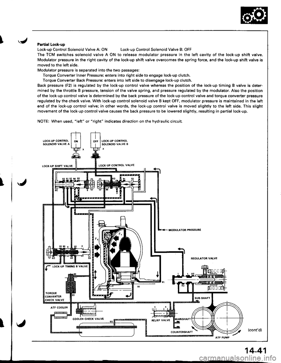
IPartial Lock-up
Lock-uo Control Solenoid Valve A: ONLock-uD Control Solenoid Valve B: OFF
The TCM switches solenoid valve A ON to release modulator Dressure in the left cavity of the lock-up shift valve.
Modulator pressure in the right cavity of the lock-up shift valve overcomes the spring force, 8nd the lock-up shift valve is
moved to the left side,
Modulator pressure is separated into the two passages:
Torque Converter Inner Pressure: enters into right side to engage lock-up clutch,
Torque Converter Back Pressure: enters into left side to disengage lock-up clutch.
Back prassure {F2) is regulated by the lock-up control valve whereas the position of the lock-up timing B valve is deter-
mined by the throttle B pressure, tension of the valve spring, and pressure regulated by the modulator. Also the position
of the lock-up control valve is determined by the back prossure of the lock-up control valve and torque converter pressure
regulated by the check valve. With lock-up control solenoid valve B kept OFF. modulator pressure is maintained in the left
end of the lock-up control valve; in other words, the lock-up control valve is moved slightly to the left side. This slight
movement of the lock-up control valve causes the back pressure to be lowered slightly, resulting in partial lock-up.
NOTE: When used, "|eft" or "right" indicates direction on the hydraulic circuit.
LOCK.UP GO TNOLSOLENOIO VAIVE A
TOCK-UP SHIFT VAIVELOCI( UP COI{TROL VAIVE
T
LOC(,UP IM TG g VALV€
MODULATOB PNESSUFE
14-41
Page 459 of 1681
Description
I,OCK UP SHIFT VALVE
Lock-up System (cont'dl
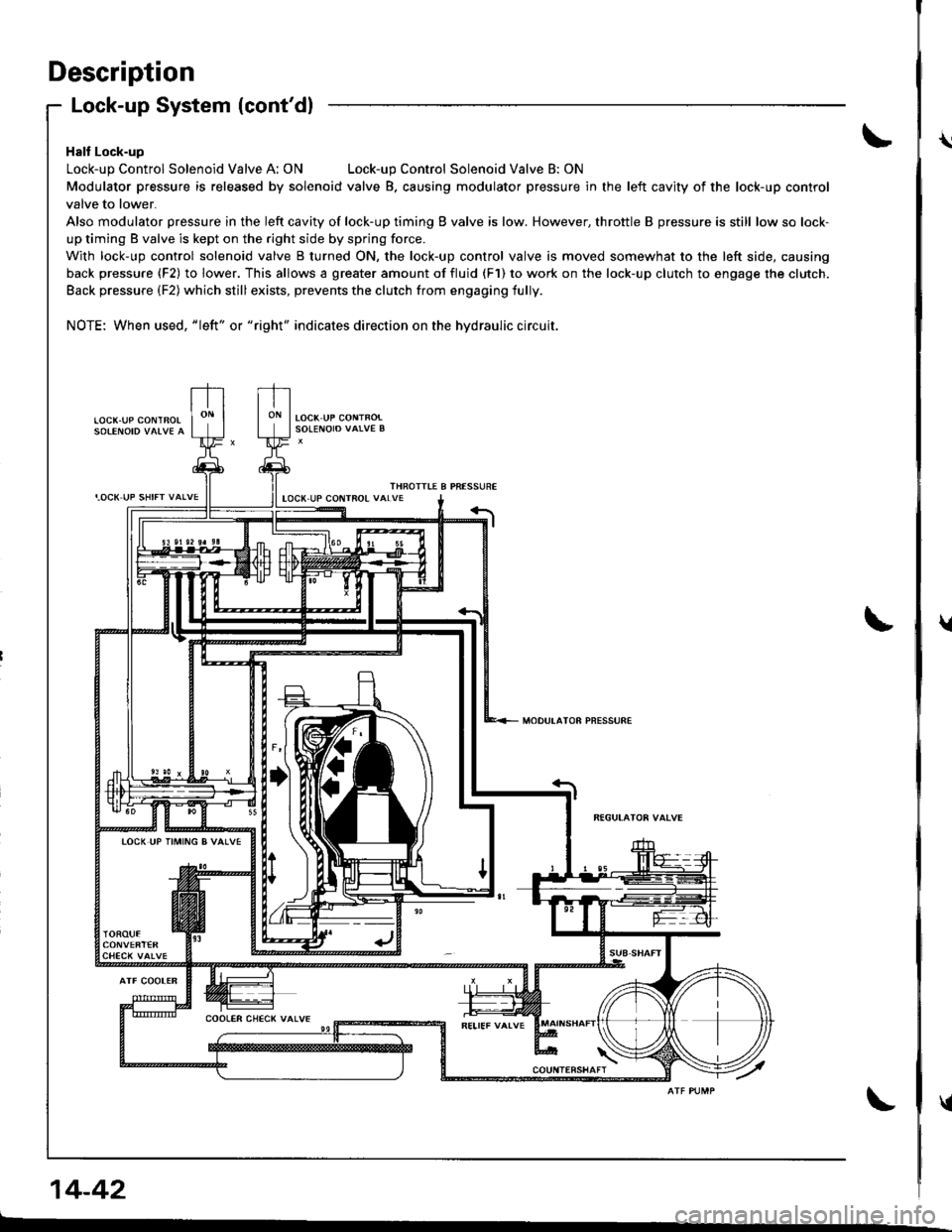
Halt Lock-up
Lock-up Control Solenoid Valve A: ONLock-up Control Solenoid Valve B: ON
Modulator pressure is released by solenoid valve B. causing modulator pressure in the left cavity of the lock-up control
valve to lower.
Also modulator pressure in the left cavity of lock-up timing B valve is low. However, throttle B pressure is still low so lock-
up timing B valve is kept on the right side by spring force.
With lock-up control solenoid valve B turned ON, the lock-up control valve is moved somewhat to the left side, causing
back pressure (F2) to lower. This allows a greater amount of fluid (F1) to work on the lock-up clutch to engage the clutch.
Back pressure (F2) which still exists, prevents the clutch from engaging fully.
NOTE: When used, "|eft" or "right" indicates direction on the hydraulic circuit.
LOCK.UP COI\ITBOL
THROITIE B PRESSUREIOCX UP COIITROL VALVE
MODULATOR PNESSURE
TOCK UP TIMING B VALVE
14-42
\
t
{
Page 460 of 1681
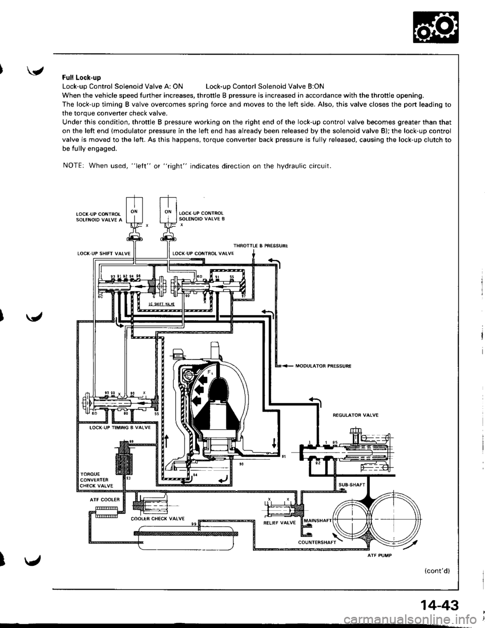
'Full Lock-up
Lock-up Control Solenoid Valve A: ONLock-uD Contorl Solenoid Valve B:ON
When the vehicle speed further increases, throttle B pressure is increased in accordance with the throttle opening.
The lock-up timing B valve overcomes spring force and moves to the left side. Also, this valve closes the port leading to
the torque convener check valve.
Under this condition, throttle B pressure working on the right end of the lock-up control valve becomes greater than that
on the left end (modulator pressure in the left end has already been released by the solenoid valve B); the lock-up control
valve is moved to the left. As this happens, torque converter back pressure is fully released, causing the lock-up clutch to
be tully engaged.
NOTE: When used, "lelt" or "right" indicates direction on the hydraulic circuit.
LOC( UP CONiBOT
LOCK UP SHIFT VAIVE
MODULATOR PBESSURE
ATF COOLER
I
IOC( UP TIMING B VALVE
14-43
Page 466 of 1681
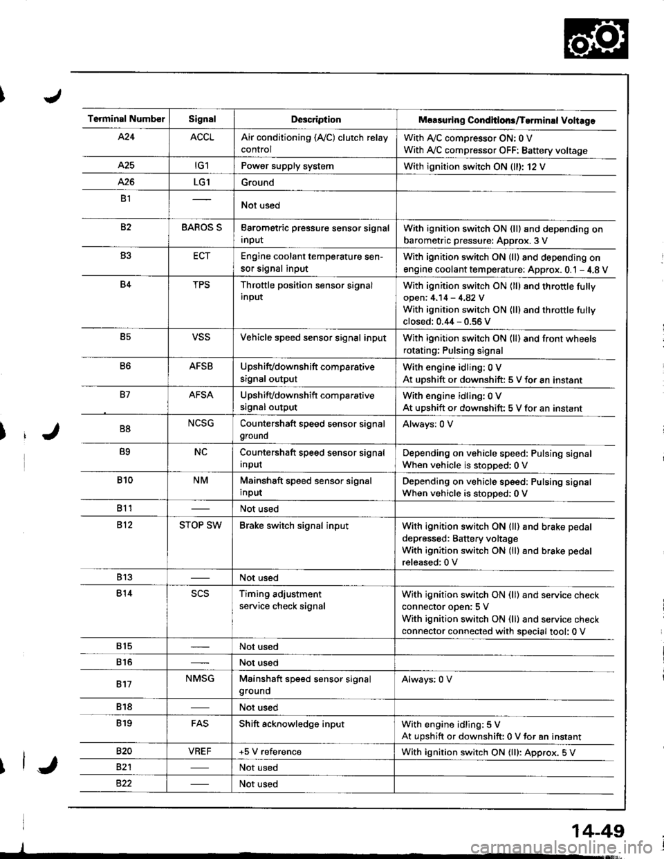
Terminal NumberSignalDescriptionMaasuring Conditlons/Tarminal Voliage
424ACCLAir conditioning (Ay'C) clutch relay
control
With A,/C comDressor ON: 0 V
With Ay'C compressor OFF: Battery voltage
A25tG1Power supply systemWith ignition switch ON (ll)r 12 V
426LG1Ground
B1Not used
82BAROS SBarometric pressure sensor signal
input
With ignition switch ON (ll) and depending on
barometric pressure: Approx. 3 V
B3ECTEngine coolant temperature sen-
sor signal input
With ignition switch ON (ll) and depending on
engine coolant tem perature: Approx. 0.1 - 4.8 V
B4TPSThrottle position sensor signal
input
With ignition switch ON (ll) 8nd throttle fully
open: 4.14 - 4.82 V
With ignition switch ON (ll) and throttle fully
closed: 0.44 - 0.56 V
B5VSSVehicle speed sensor signal inputWith ignition switch ON (ll) and front wheels
rotating; Pulsing signal
B6AFSBUpshifvdownshift comparative
signal output
With engine idling: 0 V
At uDshift or downshift: 5 V for an instant
B7AFSAUpshifvdownshift com parative
srgnal output
With engine idling: 0 V
At upshift or downshift: 5 V for an instant
B8NCSGCountershaft speed sensor signal
ground
Always: 0 V
B9NCCountershaft speed sensor signal
Input
Depending on vehicle speed: Pulsing signal
When vehicle is stopped:0 V
B10NMMainshaft speed sensor signal
input
Depending on vehicle speed: Pulsing signal
When vehicle is stoDoed: 0 V
811Not used
812STOP SWBrake switch signal inputWith ignition switch ON {ll) and b.ake pedal
depressed: Battery voltage
With ignition switch ON (lll and brake pedal
released:0 V
813Not used
814scsTiming adjustment
service check signal
With ignition switch ON (ll) and service check
connector oDen:5 V
With ignition switch ON (ll) and service check
connector connected with special tool: 0 V
815Not used
816Not used
817NMSGMainshaft speed sensor signalgroundAlways: 0 V
818Not used
819FASShift acknowledge inputWith engine idling: 5 V
At upshift or downshift: 0 V for an instant
820VBEF+5 V referenceWith ignition switch ON {lll: Approx. 5 V
82'lNot used
Not used
14-49
Page 508 of 1681
L
\a
\."tl
14-91
J
al
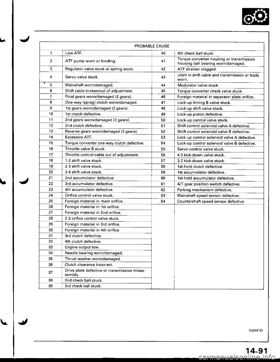
PROBABLE CAUSE
1Low ATF.404th check ball stuck.
2ATF pump worn or binding.4'lTorque converter housing or transmissionhousing ball bearing worn/damageo.
3Regulator valve stuck or spring worr..42ATF strainer clogged.
4Servo valve stuck.43Joint in shift cable and transmission or body
5Mainshaft worn/damaged.44Modulator valve stuck.
6Shift cable broken/out of adiustment45Torque converter check valve stuck.
7Final gears worn/damaged (2 gears).46Foreign material in separator plate orifice.
8One.way {sprag) clutch worn/damaged.47Lock-up timing B valve stuck.
91st gears worn/damaged {2 gears).4ALock-up shift valve stuck.
10lst clutch defective.49Lock-up piston defective.
112nd gears worn/damaged (2 gears).50Lock-up control valve stuck.
122nd clutch defective.5lShift control solenoid valve A defective.
Reverse gears worn/damaged (2 gears).52Shift control solenoid valve B defectrve.
14Excessive ATF.53Lock up control solenoid valve A defective,'t5Torque converter one-wav clutch defective.54Lock-up control solenoid valve B defective.
16Throttle valve B stuck.55Servo control valve stuck.
11Throttle control cable out of adiustment.564-3 kick-down valve stuck.
181-2 shift valve stuck.3-2 kick-down valve stuck.'192 3 shift valve stuck.lst-hold clutch defective.
203-4 shift valve stuck.59'| st accumulator defective.
2nd accumulator defective.60'lst-hold accumulator defective,
223rd accumulator delective,olA,rf gear position switch defective,
4th accumulator defective.62Parking mechanism defective.
24Orifice control valve stuck.63Mainshaft speed sensor defective.
Foreign material in main orifice.64Countershaft speed sensor defective.
26Foreign material in lst orifice.
Foreign material in 2nd orifice.
2A2-3 orifice control valve stuck.
29Foreign material in 3rd orifice.
30Foreign material in 4th orifice.
JI3rd clutch defective.
4th clutch defective.
33Engine output low.
34Needle bearing worn/damaged.
35Thrust washer worn/damaged.
36Clutch clearance incorrect.
37Drive plate defective or transmission misas-semory.
382nd check ball stuck.
393rd check ball stuck.
(cont'd)
Page 544 of 1681
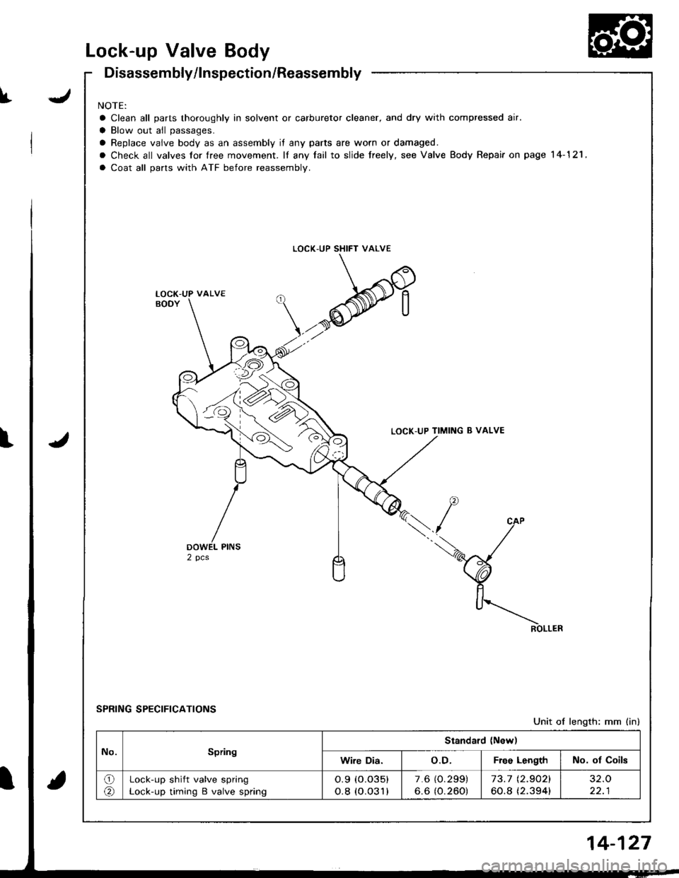
Lock-up Valve Body
JI
Disassembly/lnspection/Reassembly
NOTE:
a Clean all parts thoroughly in solvent or carburetor cleaner, and dry with compressed air.
a Blow out all passages.
a Replace vaive body as an assembly if any parts are worn or damaged.
o Check all valves for free movement. lf any fail to slide freely, see Valve Body Repair on page 14-121 ,
a Coat all parts with ATF before reassembly.
LOCK-UP SHIFT VALVE
LOCK-UP TIMING B VALVE
SPRING SPECIFICATIONS
Unit of length: mm (in)
LOCK-UP VALVE
No.Spring
Standard (New)
Wire Dia.o.D.Free LengthNo. of Coils
o(r\Lock-up shift valve spring
Lock-up timing B valve spring
o.9 (o.o35)
o.8 (o.o31)
7.6 (O.299)
6.6 (O.260)73.7 t2.9021
60.8 {2.394}
32.O
22.1
4-127
Page 791 of 1681
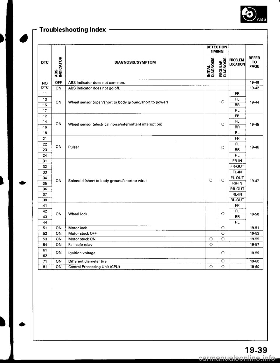
DTC
E
F
o^
e=
DIAGNOSIS/SYMPTOM
DETECTIONTIMING
PROBIEMLOCAIION
REFERTOPAGE
Io-<1
E
Y<
NODTC
OFFABS indicator does not come on.19-40
ONABS indicator does not go off.19-42
tl
ONWheel sensor (open/short to body ground/shon to power)o19-44t3FL
RR
17RL
12
ONWheel sensor (electrical noise/interminent interuption)o
FR
19-4514FL
16RR
18RL
ONPulsero
FR
19'4622
RR
24RL
ONSolenoid (short to body ground/shon to wire)oo
FR-IN
19-47
FR.OUT
33FL-IN
34FL-OUT
RR-IN
RR-OUT
37RL.IN
38RL-OUT
41
ONWheel locko19-5042FL
43RR
44RL
ONMotor locko19-51
52ONMotor stuck OFFo19-52
53ONMotor stuck ONoo19-55
54ONFailsafe relayo19-57
61ONlgnition voltageo19-59
71ONDifferent diameter tireo19-60
81ONCentral Processing Unit (CPU)oo19-60
Troubleshooting Index
19-39