engine HONDA INTEGRA 1998 4.G Owner's Guide
[x] Cancel search | Manufacturer: HONDA, Model Year: 1998, Model line: INTEGRA, Model: HONDA INTEGRA 1998 4.GPages: 1681, PDF Size: 54.22 MB
Page 164 of 1681
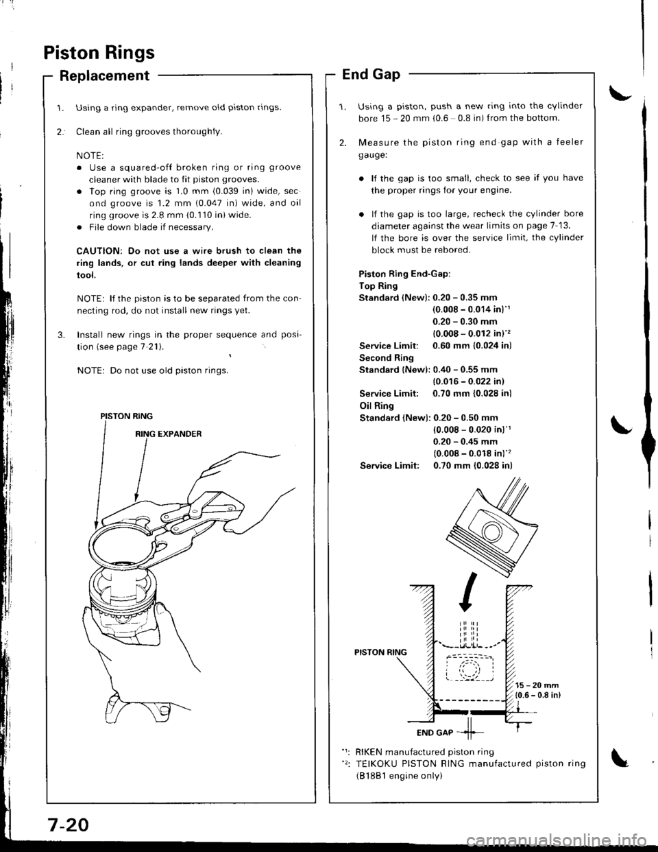
Piston Rings
Replacement
Using a ring expander, remove old piston rlngs.
Clean all ring grooves thoroughly.
o Use a squared-ofl broken ring or ring groove
cleaner with blade to fit piston grooves.
. lop ring groove is 1.0 mm (0.039 in) wide, sec
ond groove is 1.2 mm (0.047 in) wide, and oil
ring groove is 2.8 mm (0.110 in) wide.
. File down blade if necessary.
CAUTION: Do not use a wire brush to clean the
ring lands, or cut ring lands deeper with cleaning
tool.
NOTE: lf the piston is to be separated from the con
necting rod, do not install new rings yet.
Install new rings in the proper sequence and posa-
tion (see page 7 21).
Do not use old piston rings.
PISTON RING
End Gap
Using a piston, push a new ring into the cvlinder
bore 15 - 20 mm 10.6 0.8 in) f rom the bottom.
2. N,4easure the piston ring end gap with a feeler
gauge:
lf the gap is too small, check to see if you have
the proper rings for your engine.
. lf the gap is too large, recheck the cylinder bore
diameter against the wear limits on page 7-13.
lf the bore is over the service limit, the cylinder
block must be rebored.
Piston Ring End-Gap:
Top Ring
Standard (New):0.20 - 0.35 mm
(0.008 - 0.014 inl'1
0.20 - 0.30 mm
{0.008 - 0.012 in}''�
Service Limit: 0.60 mm {0.024 in)
Second Ring
Standard {New): 0.40 - 0.55 mm
{0.016 - 0.022 inl
Service Limit: 0.70 mm {0.028 inl
Oil Ring
Standard (New): 0.20 - 0.50 mm
10.008 - 0.020 in)'r
0.20 - 0.45 mm
(0.008 - 0.018 in)''�
Service Limit: 0.70 mm (0.028 in)
PISTON RING
15-20mm{0.6 - 0.8 in)
RIKEN manufactured piston ring
TEIKOKU PISTON RING manufactured piston ring
(B 1881 engine only)
Page 166 of 1681
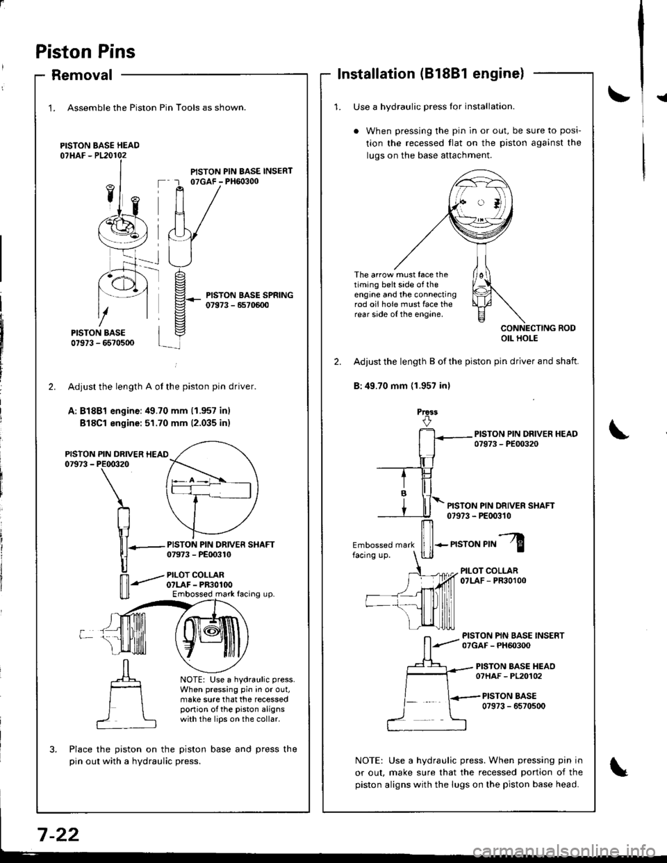
Piston Pins
Removal
1. Assemble the Piston
PISTON BASE HEAD07HAF - P120102
Pin Tools as shown.
PISTON PIN BASE INSERT07GAF - PH6o3q)
PISTON BASE SPRING07973 - 6570600
-rt_
2.
PISTON07973 -
L
PISTON PIN DRIVER SHAFT07973 - PE00310
PILOT COLLARO?LAF - PR3OlOOEmbossed mark facing up.
NOTE: Use a hydraulic press.
When pressing pin in or out,make sure that the recessedportion of the piston alignswith the lips on the collar.
?
Adjusr the length A of the piston pin driver.
A: Bl8Bl engine:49.70 mm (1.957 inl
Bl8Cl engine: 51.70 mm (2.035 inr
PIN DRIVER HEAIPE00320
\
n
\1lll-
|]
n'-"'
Place the piston on the piston base and press the
pin out with a hydraulic press.
Installation (81881 engine)
!{1. Use a hvdraulic Dress lor installation.
When pressing the pin in or out, be sure to posi-
tion the recessed tlat on the piston against the
luqs on the base attachment.
The arrow must face thetiming belt side of theengine and the connectingrod oii hole must face therear side of the engine.
CONNECTING RODOIL HOLE
2. Adjust the length B of the piston pin driver and shaft.
B:49.70 mm (1.957 inl
Prca3
PISTON PIN DRIVER SHAFT07973 - PE00310
Embossed mark
ffi-n"ro"r,"l
PILOT COLLAR07LAF - PR30100
PISTON PIN BASE INSERT07GAF - PH60300
PISTON BASE HEAO07HAF - PL20102
PISTON BASE0?973 - 6570500
NOTE: Use a hydraulic press. When pressing pin in
or out, make sure that the recessed portion of the
piston aligns with the lugs on the piston base head.
Page 168 of 1681
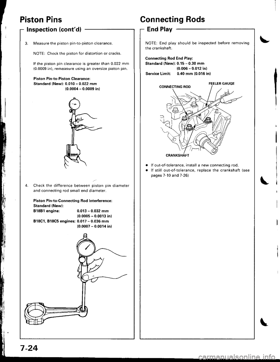
Inspection (cont'dl
3.
4.
Measure the piston pin-to-piston clearance.
NOTE: Check the piston for distonion or cracks.
fl the piston pin clearance is greater than 0.022 mm
(0.0009 in), remeasure using an oversize piston pin.
Piston Pin-to-Piston Clearancer
Standard lNewl:0.010 - 0.022 mm
(0.0004 - 0.0009 in)
Check the difference between piston pin diameter
and connecting rod small end diameter.
Piston Pin-to-Connecting Rod Interlerence:
Standard {New)i
B18Bl engine:
B18Cl, 818C5 engines:
0.013 - 0.032 mm
10.0005 - 0.0013 inl
0.017 - 0.036 mm(0.0007 - 0.0014 inl
Piston PinsConnecting Rods
End Play
\,
\
t'
NOTE: End play should be inspected before removing
the crankshaft.
Connecting Rod End Play:
Standard (New): 0.15 - 0.30 mm
10.006 - 0.012 in)
Service Limit: 0.40 mm (0.016 in)
a
a
It out-of-tolerance, install a new connecting rod.
lf still out-of-tolerance, replace the crankshaft (see
pages 7-'10 and 7-26)
7 -24
Page 169 of 1681
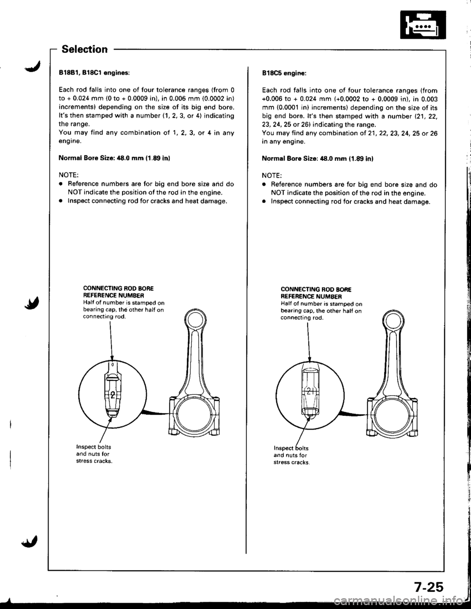
Selection
81881, 818Cl engioes:
Each rod falls into one of four tolerance ranges (from 0
to + 0.024 mm (0 to + 0.0009 in), in 0.006 mm (0.0002 in)
increments) depending on the size of its big end bore,
It's then stamped with a number (1,2,3, or 4) indicating
the range.
You may find any combination ot 1,2,3, or 4 in any
en9rne.
Normal Bore Size: /|8.0 mm (1.8, in)
NOTE:
. Reference numbers are for big end bore size aid do
NOT indicate the position of the rod in the engine.
a Inspect connecting rod for cracks and heat damage,
CONNECTING ROD BOREREFERENCE NUMBERHalf of number is stamped onbearing cap, th6 other half onconnectrng rod,
Inspect boltsand nuts forstress cracks.
B18C5 enginc:
Each rod falls into one of four tolerance ranges (from
+0.006 to + 0.024 mm {+0.0002 to + 0.0009 in). in 0.003
mm (0.0001 inl increments) depending on the size of its
big end bore. lt's then stamped with a number (21, 22,
23, 24,25 or 261 indicating the range.
You may tind any combination of 21, 22, 23, 24, 25 ot 26
in any engine.
Normal Bore Size: 48.0 mm {1.8!, in}
NOTE:
a Reference numbers are for big end bore size and do
NOT indicate the position of the rod in the engine.. Inspect connecting rod fo. cracks and heat damage.
CONNECNNG NOO BOREREFERENCE NUMAERHalf oI number is stamped onbearing cap, the other half onconnecting rod,
Inspectand nuts forstress cracks,
Page 170 of 1681
t'
Crankshaft
lnstallation
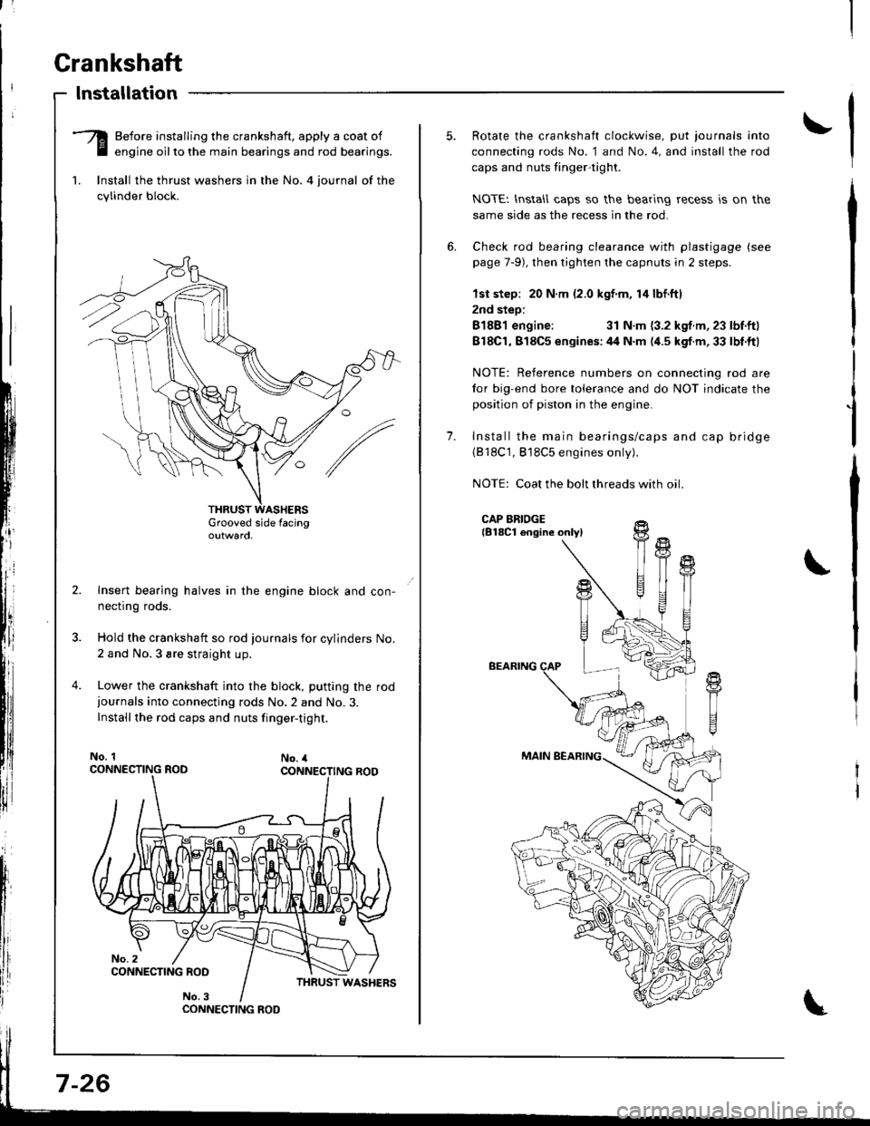
-Q Before installing the crankshaft, apply a coat of
E engine oilto the main bearings and rod bearings.
1. lnstall the thrust washers in the No. 4 iournal of the
cylinder block.
Grooved side facingoutwaro,
Insert bearing halves in the engine block and con-
necflng roos.
Hold the crankshaft so rod journals for cylinders No.
2 and No.3 sre straight up.
Lower the crankshaft into the block, putting the rod
iournals into connecting rods No.2 and No.3.
Installthe rod caps and nuts finger-tight.
No. 1No. 4
CONNECTING ROO
7-26
1.
Rotate the crankshaft clockwise, put journals into
connecting rods No. 1 and No.4, and install the rod
caps and nuts tinger-tight.
NOTEI lnstall caps so the bearing recess is on the
same side as the recess in the rod.
Check rod bearing clearance with plastigage (see
page 7-9), then tighten the capnuts in 2 steps.
lst step: 20 N.m (2.0 kgf m, 14 lbf.ftl
2nd step:
81881 engine:31 N.m (3.2 kgf.m, 23 lbf.ftl
818C1,818C5 enqines:44 N.m (4.5 kgf.m,33 lbt.ftl
NOTE: Reference numbers on connecting rod are
tor big-end bore tolerance and do NOT indicate the
position of piston in the engine.
Install the main bearings/caps and cap bridge(818C1, 818C5 engines only).
NOTE: Coat the bolt threads with oil
CAP BRIDGE{B18Cl engine onlyl
BEARING
MAIN BEARING
fi
U
t{
T
!+
T1
Page 171 of 1681
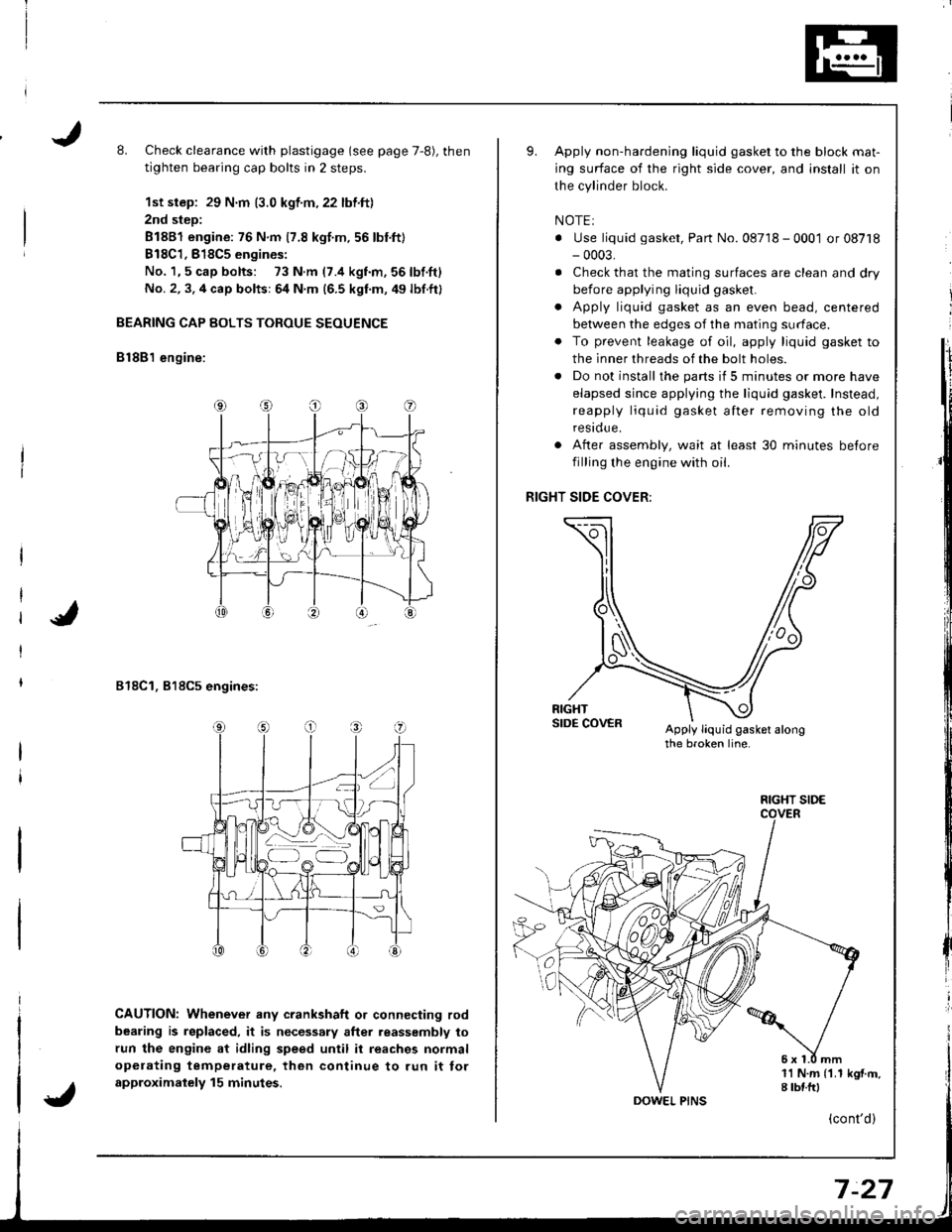
L Check clearance with plastigage (see page 7,8), then
tighten bearing cap bolts in 2 steps.
1st step: 29 N.m (3.0 kgf.m,22 lbf.ft)
2nd step:
81881 engine: 76 N.m 17.8 kgt.m.56 lbnft)
B18C1,818C5 engines:
No. 1,5 cap bolts: 73 N.m (7.4 kgnm,56lbf.ft)
No. 2, 3. 4 cap bolts: 64 N.m (6.5 kgf.m, 49 lbf.ft)
BEARING CAP BOLTS TOROUE SEOUENCE
B lSB'l engine:
818C1, 818C5 engines:
CAUTION: Whenever any crankshaft o. connecting rod
bearing is replaced, it is necessary after reassembly to
run the engine at idling speed until it reaches normal
opelating temperature, then continue to run it tor
approximalely 15 minutes.
Apply non-hardening liquid gasket to the block mat-
ing surface of the right side cover, and install it on
the cylinder block.
NOTEI
. Use liquid gasket, Part No. 08718 - 0001 or 08718- 0003,
. Check that the mating surfaces are clean and dry
before applying liquid gasket.
. Apply liquid gasket as an even bead, centered
between the edges of the mating surface.
. To prevent leakage of oil, apply liquid gasket to
the inner threads of the bolt holes.
. Do not install the parts if 5 minutes or more have
elapsed since applying the liquid gasket. Instead,
reapply liquid gasket after removing the old
residue.
After assembly, wait at least 30 minutes betore
filling the engine with oil.
RIGHT SIDE COVER:
Apply liquid gasket alongthe broken line.
o
a
1l N.m {1.1 kgf.m,I tbf.frl
FIGHT SIDE
(cont'd)
Page 172 of 1681
Crankshaft
Installation (cont'd)
I
I
t
l;I
I
fi,
\
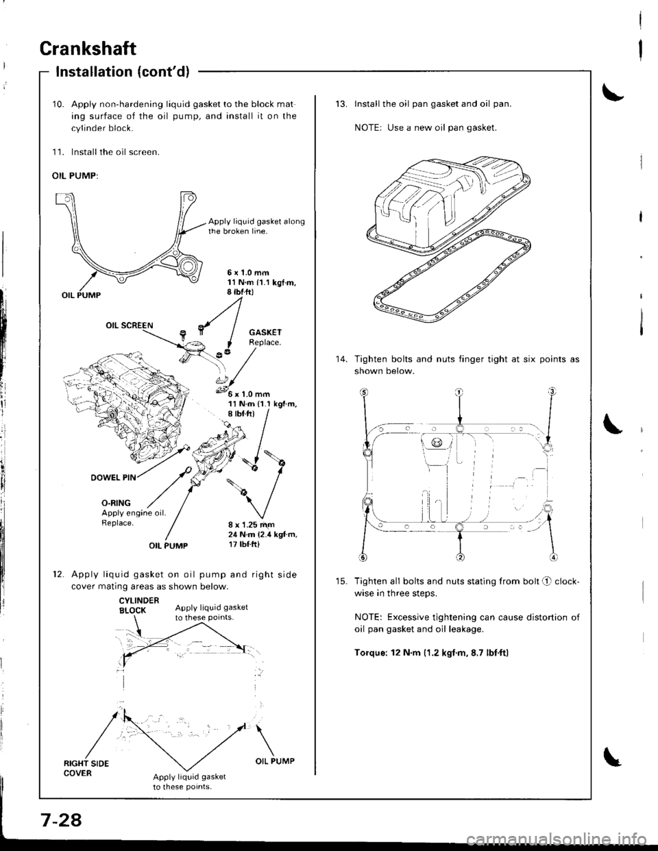
10. Apply non-hardening liquid gasket to the block mat
ing surface of the oil pump, and install it on the
cylinder block.
11. lnstall the oil screen.
OIL PUMP:
Apply liquid gasket alongthe broken line.
5x1.0mm11N.m 11.1 kgt.m,8 tbtftl
GASKETReplace.
?,' /'\, /s.../
11 N.m {1.I kgf.m,
DOWEL PIN
o-ntNG
/\
/
':'
Apply engine oil.Replace.8 x 1.25 r\m24 N.m (2.4 kgt.m,17 tbf.ft)OIL PUMP
Apply liquid gasket on oil pump and right side
cover matinq areas as shown below.
CYLINDERBI_OCK Apply liquid gasket
RIGHT SIDECOVERApply liquid gasket
to lhese potnts-
to these points.
Install the oil pan gasket and oil pan.
NOTEr Use a new oil pan gasket.
Tighten bolts and nuts finger tight at six
shown below.
points as
Tighten all bolts and nuts stating from bolt O clock-
wise in three steps.
NOTE: Excessive tightening can cause distortion of
oil pan gasket and oil leakage.
Torqus: 12 N.m (1.2 kgf.m,8.7 lbf'ftl
14.
Page 173 of 1681
Oil Seal
Installation
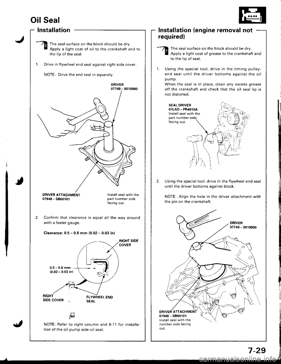
The seal surface on the block should be dry.
Apply a light coat of oil to the crankshaft and
the lip of the seal.
1. Drive in tlywheel end seal against right side cover.
NOTE: Drive the end seal in squarely.
DRIVER07749 - 0010000
Confirm that clearance is equal all the way around
with a feeler gaug€.
Clearance: 0.5 - 0.8 mm {0.02 - 0.03 inl
RIGHT SIDECOVER
lnstallation (engine removal not
requiredl
The seal surface on the block should be dry.
Apply a light coat of grease to the crankshaft and
to the lip of seal.
1. Using the special tool, drive in the timing pulley-
end seal until the driver bottoms against the oil
pump.
When the seal is in place, clean any excess grease
off the crankshalt and check that the oil seal lip is
not distoned.
SEAL DRIVER07LAD. PR4O1OAlnstall seal with thepan numberfacing out.
Using the special tool, drive in the flywheel end seal
untilthe driver bottoms aqainst block.
NOTE: Align the hole in the driver attachment with
the pin on the crankshaft.
DRIVER077{9 - 0010000
DRIVER ATT07948 - 5800101lnstall sealwith thenumber side facinqou!.
'tvA,)/ )
DBIVER ATTACHMENT07948 - 5800101Install sealwith thepan number sidefacang out.
[7Fd
NOTE: Refer to right column and 8-11
tion of the oil pump side oil seal.
for installa-
Page 174 of 1681
IJ
Engine Lubrication
Speciaf Tools ........ ........8-2
lllustrated lndex ........ ....8-3
Engine Oil
Inspection ...................... 8-6
Replacement .....,................................. 8-6
Oil Filter
Replacement ....................................... 8-7
Oil Pressure
Testing ......8-9
Oil Jet
Inspection
(818C1,818C5 engines only) ......... 3-9
OilPump
Overhaul .... 8-10
RemovaUlnspection/lnstallation ...... 8-1 1
tr---rl
r-"- i
Page 176 of 1681
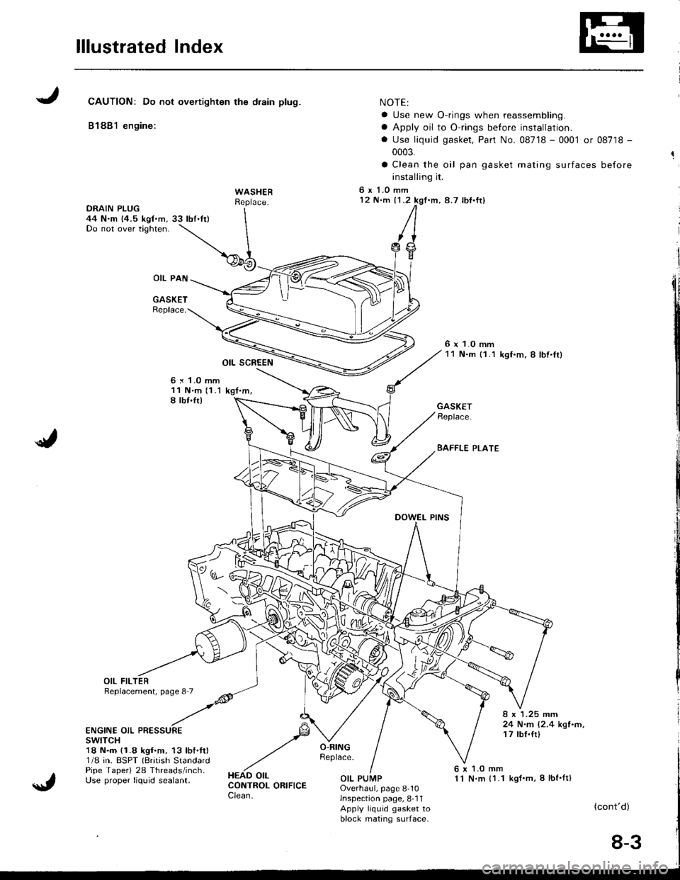
lllustrated Index
JCAUTION: Do not overtighton the drain plug.
81881 engine:
WASHER
OIL PAN
GASKETReplace.
OIL SCREEN
6 x 1.0 mm11 N'm 11.1 kgt.m,I lbt.ft)
NOTE:
a Use new O-rings when reassembling.
a Apply oil to O-rings before installation.
. Use liquid gasket, Pan No. 08718 - 0001 or 08718 -
0003.
a Clean the oil pan gasket mating surfaces before
installing it.
6 x 1.O mm12 N'm {1.2 kgf.m,8.7 lbf'fr)
/I
,trg
6 x 1.0 mm11 N.m {1.1 kgf.m, 8 lbl.ft}
./
GASKETReplace.
BAFFLE PLATE
8 x 1.25 mm24 N.m 12.4 kgl.n,17 tbf.tt)ENGINE OIL PRESSUREswtTcH18 N.m (1.8 kgf.m. 13 lbf.ft)1/8 in. BSPT (British StandardPipe Taper) 28 Threads/inch-Use proper liquid sealant.
6 x 1.O mm1 l N.m {1.1 kgt.m, I lbf'ft}OIL PUMPOverhaul, page 8-10lnspection page, 8-11Apply liquid gasket toblock mating s(]lrface-
(cont'd)
8-3