engine HONDA INTEGRA 1998 4.G User Guide
[x] Cancel search | Manufacturer: HONDA, Model Year: 1998, Model line: INTEGRA, Model: HONDA INTEGRA 1998 4.GPages: 1681, PDF Size: 54.22 MB
Page 58 of 1681
Engine Removal/lnstallation
{cont'dl
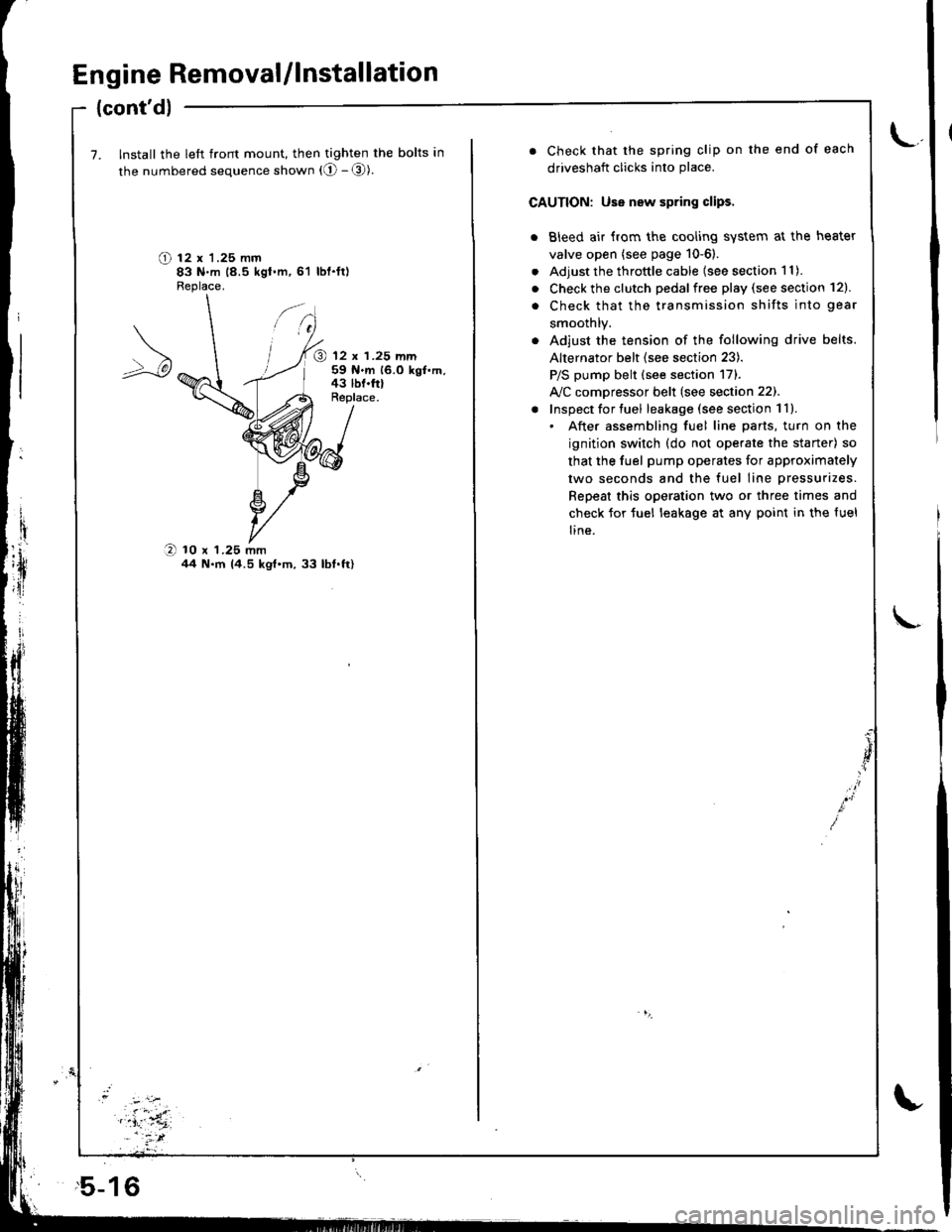
7. Install the left front mount, then tighten the bolts in
the numbered sequence shown (O - @).
O t2 x '1.25 mm83 N.m 18.5 kgt.m,61 lbl.ft)Fleplace.
@ 12 x 1.25 mm59 N.m 16.0 kgf.m,43 lbf.frlReplace.
O 10 x 1.25 mmil4 N.m 14.5 kgt'm,33 lbt.ft)
,5-16
. Check that the spring clip on the end of each
driveshaft clicks into place.
CAUTION: Use new spring clips.
. Bleed air {rom the cooling system at the heater
valve open (see page 10-6).
. Adjust the throttle cable (see section 1 1).
. Check the clutch pedalfree play (see section 12).
. Check that the transmission shifts into gear
smoothlY.
. Adjust the tension of the following drive belts.
Alternator belt {see section 23).
P/S pump belt (see section 171.
A/C comDressor belt (see section 22).
! Inspect for tuel leakage (see section 1ll.. After assembling fuel line parts, turn on the
ignition switch (do not operate the staner) so
that the fuel pump operates for approximately
two seconds and the fuel line pressurizes.
Repeat this operation two or three times and
check for tuel leakage at any point in the {uel
line.
Page 62 of 1681
I
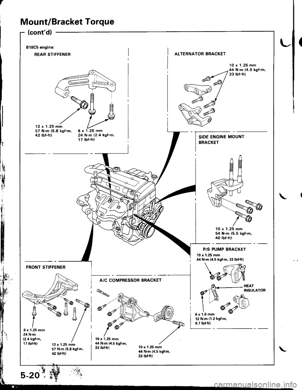
Mount/Bracket Torque
(cont'dl
818C5 engine:
REAR STIFFENER
(
ALTERNATOR BRACKET
10 r 1.25 mm
12 x 1.25 mm57 N.m {5.8 kgf.m,42 tbt'trt24 N.m 12.4 kgl.m,17 rbf'ftt
--q;;/44N'mtr.5kst'm'v=ahp /
w#
q7
10 x 1.25 mm54 N.m 15.5 kgf.m.40 rbt.frl
P/S PUMP BRACKET
10 x 1.25 mm
t:
ltri
rH
{ir
I\
; /r/r N.m {4.5 kgf.m, 33 lbtftl
FRONT STIFFENER
A/C COMPRESSOR BRACKET
I x'1.25 mm24 N.m(2.4 kgf'm,17 rbf.ft)12 x 1.25 mm57 N.m 15.8 kgt.m,42 lbf.ftt
6\--- HEAr
d'1N ^rNsuLAroR
I --H Gh\
"
*o-r$l/
sxrlomm v
12 N.m 11.2 kgf.m.8.7 tbf.ftt
Page 70 of 1681
Grankshaft Pulley Bolt
Replacement
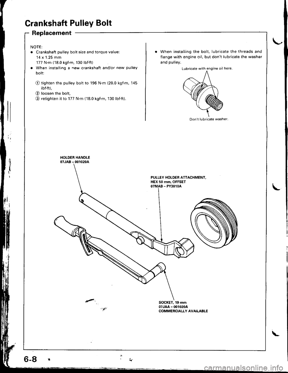
NOTE:
o Crankshaft pulley bolt size and torque value:'14 x 1.25 mm
177 N.m (18.0 kgf m, 130 lbtft)
a When installing a new crankshaft and/or new pulley
bolt:
O tighten the pulley bolt to 196 N.m (20.0 kgim, 145
lbf.ft),
@ loosen the bolt,
o retighten it to 177 N.m (18.0 kgf.m, 130 lbift).
When installing the bolt, lubricate the threads and
flange with engine oil, but don't lubricate the washer
and DUllev.
Don't lubricate washer.
PULLEY HOLDEB ATTACHMENI,HEX 50 mm, OFFSETOTMAB - PY3O1OA
SOCKET, 19 mm07JAA - @1020ACOMMERCIALLY AVAILABLE
\-
Page 78 of 1681
Gylinder Head
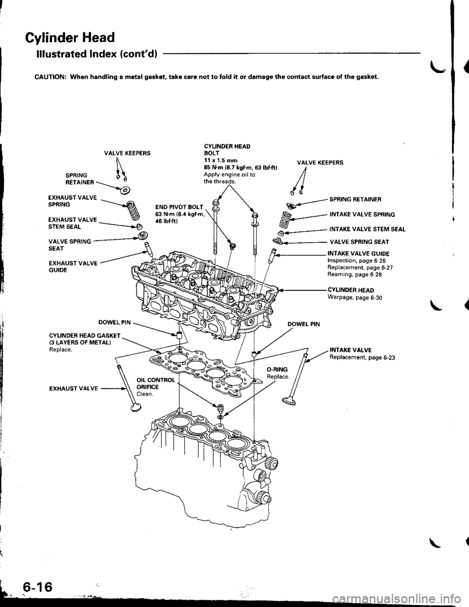
lllustrated Index (cont'd)
CAUTION: When handling a mstal ga€kot, take care not to fold it o. damage the contact surfac6 ol the gasket.{
VALVE KEEPERS
\
SPRTNG [\RETaTNER\_>6
CYLINDER IIEAOAOLT11 x'1.5 mm
EXHAUST VALVE
EXHAUST VALSPRINGs------.--
r
€.-=---
€<_-
VALVE KEEP€NS
DOWEL PIN
SPRING AEIAINER
INTAKE VALVE SPRING
INTAKE VALVE STEM SEAL
VALVE SPRING SEAT
ENO PIVOT BOLT63 N.m {6.4 kgf.m,46 tbt.ftlSIEM SEAL
VALVE SPRINGSEAT
-----------rg
,@
EXHAUST VALVEGUIDE
INTAKE VALVE GUIDEInspection. page 6 26Replacement, page 6,27Reaming, page 6 28
CYLINDER HEADWarpage, page 6,30
L
DOWEL PIN
CYLINDER HEAD GASKET(3 LAYERS OF METALIReplace.
EXHAUST VALVE
85 N.m (8.7 kgtm, 63 lbf.ft) IApply engine oilto /lthe threads. / |
/ {e
\
Page 80 of 1681
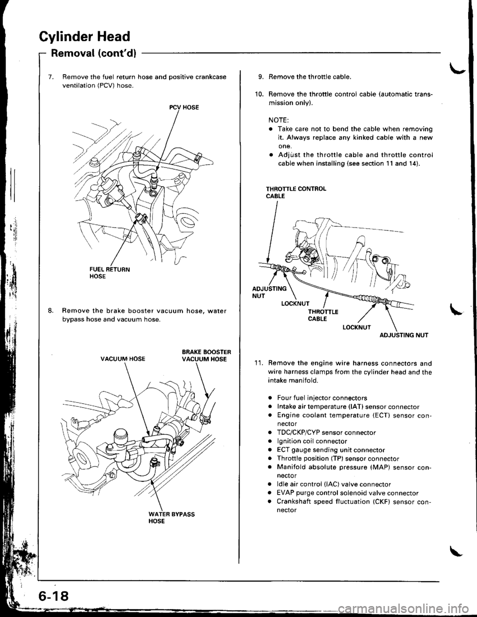
Gylinder Head
Removal (cont'dl
Remove the fuel return hose and positive crankcase
ventilation (PCV) hose.
Remove the brake booster vacuum hose, water
bypass hose and vacuum hose.
ltosE
VACUUM HOSE
6-18
10.
9.
11.
Remove the throttle cable,
Remove the throttle control cable (automatic trans-
mission only).
NOTE:
. Take care not to bend the cable when removing
it. Always replace any kinked cable with a new
one.
. Adjust the throttle cable and throttle control
cable when installing (s€e section 11 and 14).
THROTTLE CONTROLCABLE
ADJUSTING NUT
Remove the engine wire harness connectors and
wire harness clamps f.om the cylinder head and the
intake manifold.
Four fuel injector connectors
Intake air temperature (lATl sensor connector
Engine coolant temperature {ECT) sensor con,
nector
TDC/CKP/CYP sensor connector
lgnition coil connector
ECT gauge sending unit connector
Throttle position (TP) sensor connector
Manifold absolute pressure (MAP) sensor con-
necto r
ldle air control (lAC) valve connector
EVAP purge control solenoid valve connector
Crankshaft speed fluctuation (CKF) sensor con-
nector
a
a
a
a
a
a
a
a
ADJUSTING
Page 82 of 1681
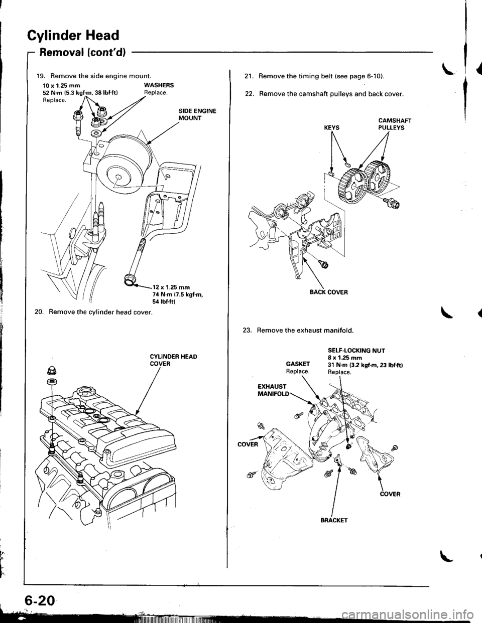
Gylinder Head
Removallcont'd)
19. Remove the side engine mount.
10 x 1.25 mm52 N.m {5.3 kgt:m, 38 lbl.ft}
20. Remove the cylinder head cover.
SIDE ENGINEMOUNT
12 x 1.25 mm74 N.m 17.5 kgt.m,sil lbtft)
CYLINOER HEADCOVER
t
L
I'
L21.
22.
Remove the timing belt (see page 6- 10).
Remove the camshaft pulleys and back cover.
CAMSHAFTPULLEYS
23. Remove the exhaust manifold.
GASKETReplace.
SELF.LOCKING NUT8 x 1.25 mm3'l N.m 13.2 kgl.m, 23 lbf.ftlReplace.
Page 92 of 1681
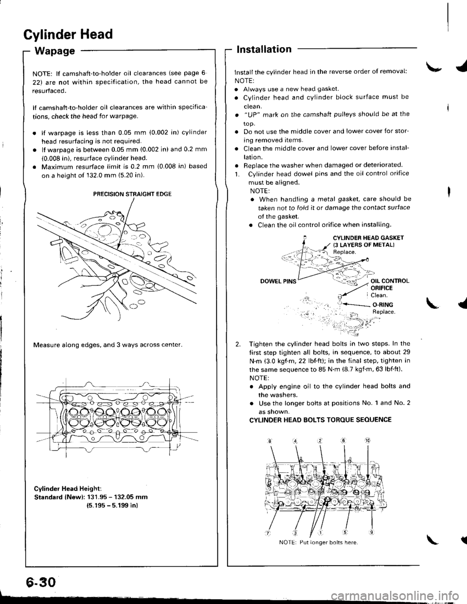
Cylinder Head
Wapage
NOTE: lf camshaft-to-holder oil clearances (see page 6
22) arc nol within specification, the head cannot be
resurfaced.
lf camshaft-to-holder oil clearances are within specifica-
tions, check the head for warpage.
lf warpage is less than 0.05 mm (0.002 in) cylinder
head resurfacing is not required.
lf warpage is between 0.05 mm (0.002 in) and 0.2 mm
(0.008 in). resurface cylinder head.
Maximum resurface limit is 0.2 mm (0.008 in) based
on a height of 132.0 mm (5.20 in).
Measure along edges, and 3 ways across center.
Cylinder Head Height:
Standard lNewl: 131.95 - 132.05 mm(5.195 - 5.199 inl
lnstallation
Install the cylinder head in the reverse order of removal:
NOTE:
. Always use a new head gasket.
. Cylinder head and cYlinder block surface must be
clean.
. "UP" mark on the camshaft pulleys should be at the
to p.
. Do not use the middle cover and lower cover for stor-
ing removed items.
. Clean the middle cover and lower cover before instal-
lation.
. Replace the washer when damaged or deteriorated
L Cylinder head dowel pins and the oil control orifice
must be aligned.
. When hand'ing a metal gasket, care should be
taken not to fold it or damage the contact surface
of the gasket.
. Clean the oil control orifice when installing,
OIL CONTROLORIFICE
PRECISION STRAIGHT EDGE
6.30
CYLINDER HEAD GASKET
{3 LAYERS OF METAL)
DOWEL
Tighten the cylinder head bolts in two steps. In the
tirst step tighten all bolts, in sequence, to about 29
N.m (3.0 kgf.m,22 lbf.ft); in the final step. tighten in
lhe same sequence to 85 N.m (8.7 kgnm,63 lbf.ft).
NOTE:
. Apply engine oil to the cylinder head bolts and
the washers.
. Use the longer bolts at positions No. 1 and No. 2
as snown,
CYLINDER HEAD BOLTS TOROUE SEOUENCE
\.l
tNOTE: Put longer bolts here.
t-
Page 95 of 1681
15.
16.
17.
Install the timing belt (see page 6-12).
Adjust the valve clearance (see page 6-3).
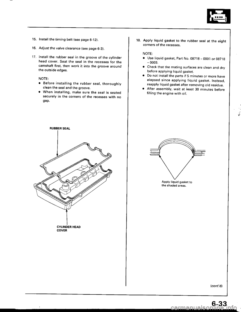
lnstall the rubber seal in the groove of the cylinderhead cover. Seat the seal in the recesses for thecamshaft first, then work it into the groove aroundthe outside edges.
NOTE:
. Before installing the rubber seal, thoroughlyclean the seal and the groove.
. When installing, make sure the seal is seatedsecurely in the corners of the recesses with nogap.
RUEBER SEAL
18.Apply liquid gasket to the rubber seal at the eightcorners of the recesses.
NOTE:
. Use liquid gasket, Part No. 08718 - OO01 or 08718- 0003.
. Check that the mating surfaces are clean and drybefore applying liquid gasket.. Do not installthe parts if 5 minutes or more naveelapsed since applying liquid gasket. Instead,reapply liquid gasket after removing old residue.. After assembly, wait at least 30 minutes beforefilling the engine with oil.
Apply liquid gasket tothe shaded areas.
(cont'd)
6-33
Page 147 of 1681
I
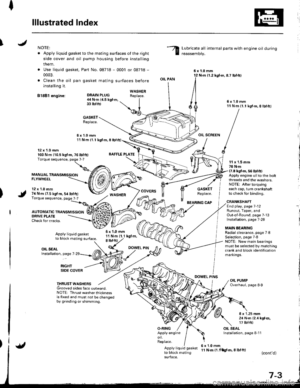
lllustrated Index
INOTE:
. Apply liqujd gasket to the mating surfaces ot the right
side cover and oil pump housing before installing
them.
. Use liquid gasket,
0003.
. Clea n the oil pan
installing it.
B18Bl engine:
Part No. 087'18 - 0001 or 08718 -
gasket mating surfaces before
Lubricate all internal parts with engine oil during
reassemDly.
6x1.0mm12 N.m {1.2 kg{.m,8.7 lbt.ft}
6x1.0mm11 N.m 11.1 kg'f.m,8 lbt.ftl
OIL SCREEN
DEAIN PLUG4il N.m 14.5 kgt m,33 tbtft)
BAFFLE PLATE
6x1.0mm1'l N.m (1.1 kgt.m,8 rbr.ftl
OIL PAN
O.FING
CAP
DOWEL PINS
WASHERReplace.
GASKETReplace.
6x1.0mm11 N.m (1.1 kgl.m, 8 lbl.ft)
12 x 1.0 mm103 Nm 110.5ks{.m,76lbf.ft}
MANUAL TRANSMISSIONFLYWHEEL
12 x 1.0 mm74 N.m 17.5 kgf.m,54lbf.tr)Torque sequence, page 7-7
AUTOMATIC TRANSMISSION
WASHERcovERsGASKETReplace.
11 x 1.5 mm76 N.m17.8 kgt m, 56 lbtft)Apply engine oilto the boltthreads and the washers.NOTE: After torquingeach cap, turn crankshaftto check for binding.
ORIVE PLATECheck for cracks.
Apply liquid gasketto block mating surface.
CRANKSHAFTEnd play, page 7-12Runout, Taper, andOut-of'Round, page 7-13Installation, page 7-26
MAIN AEARINGRadialclearance, page 7 8Selection, page 7'8NOTE: New main bearingsmust be selected by matchingcrank and block identificationmarkrngs.
I
i
OIL SEALlnstallation, page 7
RIGHTSIDE COVER
THRUST WASHERSGrooved sides face outward.NOTE: Thrust washer thicknessis fixed and must not be changedby grinding or shamming.
8 x 1.25 mm21 N..n l2.1kga'r,�,17 tbf.ft)
OIL SEALInstallation, page 8-1 1Apply engineorl.Replace.
Apply liquid gasket
to block matingsurface,
6x1.0mm11 N.m t1.lilh{.m,I lbf.ft}(cont'd)
Page 149 of 1681
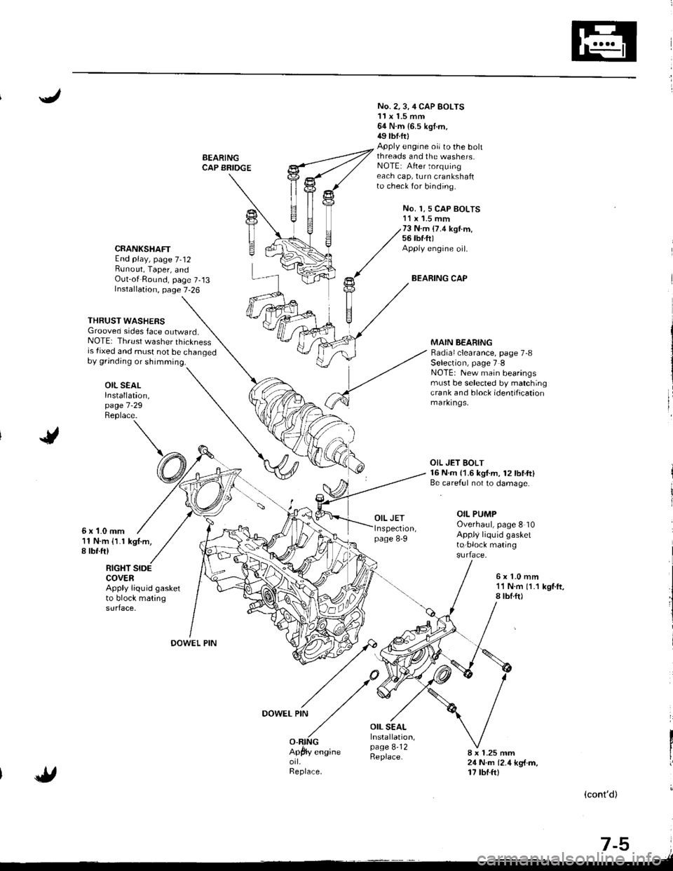
BEARINGCAP BRIOGE
No. 2.3,4 CAP BOLTS11x 1.5 mm64 N.m {6.5 kgt.m,49 tbtftlApply engine oi/ to the bohthreads and the washers.NOTE: After torquingeach cap, turn crankshaftto check for binding.
No. 1,5 CAP BOLTS11 x '1.5 mm73 N.m (7.4 ksl.m,56 tbf.ft)Apply engine oil.
BEARING CAP
CRANKSHAFTEnd play, page 7-12Bunout, Taper, andOut-of Round, page 7-13Installation, page 7-26
THRUST WASHERSGrooved sides face outward_NOTE: Thrust washer thicknessis {ixed and must not be changedby grinding or shimming.
OIL SEALInstallation,page 7 -29
Replace.
MAIN BEARINGRadial clearance, page 7-8Selection, page 7 INOTE: New main bearingsmust be selected by matchingcra nk and block identificationmarkrngs,
6x1-0mm11 N.m {l.1 kgf.m,I rbr.ft)
OIL JET BOLT16 N.m {1.6 kgf.m, 12lbtft}Be.careful not to damage.
OIL PUMPOverhaul, page 8 10Appl/ liquid gasketto:block mating
RIGHT SIDECOVERApply liquid gasketto block matingsurface.
6x1.0mm11 N.m 11.1 kgf.ft,8lbf.ft)
OOWEL PIN
DOWEL PIN
OIL SEALInstallation,page 8-12Replace.8 x 1.25 mm24 N.m {2.4 kg{.m,17 tbt.ftl
(cont'd)
-,tr
t-9 i.lt