Manual HONDA INTEGRA 1998 4.G Service Manual
[x] Cancel search | Manufacturer: HONDA, Model Year: 1998, Model line: INTEGRA, Model: HONDA INTEGRA 1998 4.GPages: 1681, PDF Size: 54.22 MB
Page 1397 of 1681
How To Use This Manual
Troubleshooting Tests
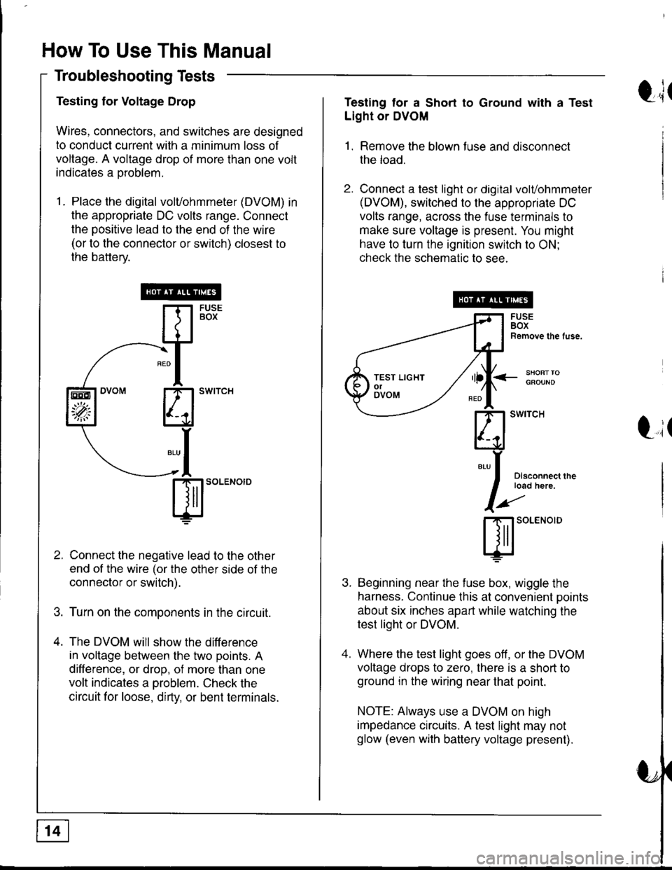
Testing for Voltage Drop
Wires, connectors, and switches are designed
to conduct current with a minimum loss of
voltage. A voltage drop of more than one volt
indicates a oroblem.
1. Place the digital volvohmmeter (DVOM) in
the appropriate DC volts range. Connect
the positive lead to the end of the wire
(or to the connector or switch) closest to
the battery.
Connect the negative lead to the other
end of the wire (or the other side of the
connector or switch).
Turn on the components in the circuit.
The DVOM will show the difference
in voltage between the two points. A
difference, or drop, of more than one
volt indicates a oroblem. Check the
circuit for loose, dirty, or bent terminals.
sl'o""o'o
EEO
'p;
t;tTesting tor a Short to Ground with a Test
Light or DVOM
1. Remove the blown fuse and disconnect
the load.
2. Connect a test light or digital volvohmmeter
(DVOM), switched to the appropriate DC
volts range, across the fuse terminals to
make sure voltage is present. You might
have to turn the ignition switch to ON;
check the schematic to see.
<_SHOFTTOGFOUND
t,it
I
Disconnect theload here.
SOLENOID
Beginning near the f use box, wiggle the
harness. Continue this at convenient ooints
about six inches apart while watching the
test light or DVOM.
Where the test light goes off, or the DVOM
voltage drops to zero, there is a short to
ground in the wiring near that point.
NOTE: Always use a DVOM on high
impedance crrcuits. A test light may not
glow (even with battery voltage present).
TEST LIGHTolOVOM
Page 1399 of 1681
How To Use This Manual
Troubleshooting Tests (cont'd)
4. Turn on the shon finder. This creates a
pulsing magnetic f ield around the wiring
between the fuse box and the short.
5. Beginning at the fuse box, slowly move
the short finder along the circuit wiring.
The meter will show current oulses
through sheet metal and body trim. As
long as the meter is between the fuse and
the short, the needle will move with each
current pulse. Once you move the meter
past the point of the short, the needle will
stop moving. Check the wiring and
connectors in this area to locate the cause
of the short.
tr(
Li(
Page 1432 of 1681
![HONDA INTEGRA 1998 4.G Service Manual - Manual Transmission
NOTE: For cars equipped with optional security system, see security system, page 133-3 for starting
system circuit schematic.
c432
FUSE 42tGl
c216
r
I
I
I
I
I
I
I
I
I
]
UNDER.HOO](/img/13/6069/w960_6069-1431.png "HONDA INTEGRA 1998 4.G Service Manual - Manual Transmission
NOTE: For cars equipped with optional security system, see security system, page 133-3 for starting
system circuit schematic.
c432
FUSE 42tGl
c216
r
I
I
I
I
I
I
I
I
I
]
UNDER.HOO")
- Manual Transmission
NOTE: For cars equipped with optional security system, see security system, page 133-3 for starting
system circuit schematic.
c432
FUSE 42tGl
c216
r
I
I
I
I
I
I
I
I
I
]
UNDER.HOODFUSE/RELAYBOX
ELECTRICALloAoDETECTOR(ELD) UN|T
START(10
c432
.Joil0t)
BLKWHT
1
BLK/IVHT
(o) ,t-,>
0)
,i
I
l
Ia
I
I
I
I
BLKA''HT II--2 A cqqz
"4
".u,".0^ tr-
- -----
t I coee
Hifr*',;*-"J
":-r
"*'
: See Ground
I Rl"i:b,*?"
""1;
' PHOIO 56
STARTERCUTRELAY
See PowerDistribution,page 10.
T1PHO|Q22
BLK/REO
BLK/BEO
a=z
lt
lta c444
Used)
c444All exceptUSA RS
See PolYerDistribution,page 10.
BLK/REO
1
ALK/WHI
c301
c126PHOTA 36c440
BATTERYSTARTERrrF-----1
! { H:.i,r'",""^. I
li ?.ea I
!l';Lg" i
|r | |
ill l lllL-J I! I INTEGRATED ]| | coNrRoL I
Ll'l,l't--i
UNDER.DASHFUSE/RELAYBOX
See PGM'Fl, page 23-l('98-99) or 24-1 ('00).
t2 A Clos
-a- G1
21-1
Page 1452 of 1681
- How the Circuit Works
With the ignition switch in ON (ll) or START (lll),
battery voltage is supplied through fuse 15 and the
BLK//EL wire to the vehicle speed sensor (VSS).
The sensor is grounded by the BLK wire to G101.
The speedometer and other control units in the
circuit supply about 5 volts to the ORN wire. The
vehicle speed sensor (VSS) intermittently grounds
the ORN wire which generates a pulsed signal in it.
The number of pulses per minute increases/
decreases with the speed of the car
Refer to the Service Manual (Section 23, Electrical)
for specific tests or troubleshooting procedures.
33-1
Page 1457 of 1681
Cruise Control (cont'd)
- How the Circuit Works
The cruise control system uses mechanical and
electrical devices to maintain the car's soeed at a
setting selected by the driver.
System Description
The cruise control unit receives command signals
from the cruise control main switch and the cruise
control SevBesume switch. With the ignition switch
in ON (ll) or START (lll), voltage is provided to the
cruise control main switch. When you push the
switch to on, power is provided to the cruise control
unit and the brake switch.
The cruise control unit receives information about
operating conditions from the brake switch, the
ignition control module (lCM), the vehicle speed
sensor (VSS), and the clutch switch (manual
transmission) or the A,/T gear positton switch
(automatic transmission). The cruise control unit
then sends signals to the cruise conirol actuator
which regulates the throttle position to maintain the
selected speed. The control unit compares the
aclual speed of the car to the selected speed. The
control unit then uses the result of that comoarison
to oDen or close the throttle.
The brake switch releases the system's control of
the throttle at the instant you press on the brakepedal. The switch sends a signal to the control unit
by removing power from the normally closed brake
input (GRY wire), and providing power at the
normally open brake input (GRNMHT wire). The
control unit responds by allowing the throttle to
close. The clutch switch or the A/T gear position
switch sends a "disengage" signal to the control unit
that also allows the throttle to close.
The cruise control system will set and automatically
maintain any speed above 25 mph (40 km/h). To set
it, make sure the main switch is on and the switch
indicator is on. Then, after reaching the desired
speed, press the set switch. This sends a "set"
signal to the cruise control unit which, in turn,
controls the cruise control actuator to maintain the
set soeed.
When you push the SET switch and the cruise
control system is on, the "cruise control" ON
indicator lights up.
34-4
You can cancel the cruise control system by
turning the main switch off. This removes power to
the control unit and erases the set sDeed from
memory. lf the system is disengaged temporarily
by the brake switch, or clutch switch, and the car's
speed is still above 25 mph, press the RESUME
switch: the car will automatically return to the
previously set speed.
For gradual acceleration without pressing the
accelerator pedal, push the RESUME switch and
hold it there. This will send an "acceleration" signal
to the control unit. When you release the switch, the
system will be reprogrammed tor the new speed. To
slow the car down, push the SET switch in and hold
it there. This sends a "deceleration" signal to the
control unit, causing the car to coast. When the
desired speed is reached, release the SET switch.
This reprograms the system for the new speed.
Reter to the Service Manual (Section 23, Electrical)
for specific tests or troubleshooting procedures.
Page 1476 of 1681
Air Deliver| (cont'd)
- How the Circuit Works
The air delivery system directs the flow of air used
by the heater and air conditioner systems.
Mode Selection
Mode selection is controlled by the mode switches in
the heater control panel and the mode control motor.
When you select a specific mode, voltage is applied
through the dimming control circuit to the LED, which
comes on, indicating the mode selected. Ground is
provided to the mode control motor though that
mode switch. The motor then runs until the air
control door reaches the proper position.
Fresh/Recirculation Selection
When you press the recirculation button, a ground
signal is sent from the heater control panel to the
recirculation control motor. The motor lhen runs
until the recirculation door reaches the opposite
Dosition. When the recirculation button is in the
REC position, battery voltage is applied through the
dimming control circuit to the recirculate LED, and
the LED comes on.
Refer to the Service Manual (Section 21, Heate0 for
specif ic tests or troubleshooting procedures.
61-2
Page 1479 of 1681
A/C Gompressor Controls (conrd)
- How the Circuit Works
Battery voltage is supplied through fuse 56 to the
A,/C compressor clutch relay contacts at all times.
With the ignition switch in ON (ll), voltage is applied
to the coil of the A,/C compressor clutch relay
through fuse 17. When you push the A,/C switch
ON, and the heater fan switch is in posation 1, 2, 3,
or 4, a "ground" input is provided to the engine or
powertrain control module (ECM or PCM) through
the A,/C thermostat and the A,/C pressure switch.
The A,/C compressor clutch relay is grounded by the
engine or powertrain control module (ECM or PCM).
When energized, the A,/C compressor clutch relay
allows battery voltage to turn on the A,/C
comDressor clutch,
The A,/C ON indicator light comes on when the A"/C
system is requested.
A,/C Thermostat
The A,/C thermostat is located on the evaoorator
housing. The AJC thermostat turns off the A,/C
compressor clutch if the temperature at the
evaporator goes below 3'C (37'F). This prevents
condensation from freezing on the evaporator fins
and blocking the air delivery into the passenger
compartment. The blower motor will keep running
when the sensor lurns off the compressor.
A,/C Pressure Switch
The A,/C pressure switch is located in the condenser
outlet line where refrigerant is in a high
temperature/high pressure liquid state. The switch
will sense abnormally high or low pressure, and
open the circuit. This removes ground, and the
compressor will stop running.
Refer to the Service Manual (Section 22,
Air Conditioning) for specific tests or
troubleshooting procedures.
62-2
Page 1483 of 1681
Fans (cont'd)
- How the Gircuit Works
When the ignition switch is in ON (ll), voltage is
applied to the coils of the radiator fan relay and the
condenser fan relay (with A,/C) through fuse 17.
Whenever a ground is provided to the radiator fan
relay and condenser fan relay, the relays are
energized, turning on the radiator fan motor and
condenser fan motor. The relays can be grounded
by the radiator fan switch, engine or powertrain
control module (ECM or PCM) (USA), or the A,/C
and heater lan switches via the A'lC pressure switch
and the A,/C lhermostat.
A,/C Thermostat
The A,/C thermostat is located on the evaporator
housing. The A/C thermostat turns oft the A/C
compressor clutch it the temperature at the
evaporator goes below 3'C (37"F). This prevents
condensalion from freezing on the evaporator fins
and blocking the air delivery into the passenger
compartment. lt the temperature goes below 3'C
(37'F) turning off the A"/C thermostat, and the
BLU/RED wire at the A,/C diode was the only wire
providing ground to the condenser and radiator
fan relays (A,/C switch on, heater fans switch on,
radiator fan switch open, and ECM or PCM fan
controi output not grounded), the relay will
deenergize removing voltage from the condenser
and radiator fan motors causing them to stop
running.
A,/C Pressure Switch
The AJC oressure switch is located in the condenser
outlet line where refrigerant is in a high
temperature/high pressure liquid state. The A,/C
switch turns off the A,/C compressor clutch if it
senses abnormally high or low pressure. lf the A'lC
pressure switch opens, and the BLU/RED wire at
the A/C diode was the only wire providing ground
to the condenser and radiator fan relays (L/C switch
on, heater fans switch on, radiator lan switch open'
and ECM or PCM fan control output not grounded),
the relay will deenergize removing voltage from the
condenser and radiator fan motors causing them to
stop running.
A./C Diode
This diode orevents the radiator fan switch f rom
grounding the "A'lC ON" input to the engine or
powertrain control module (ECM or PCM).
Refer to the Service Manual (Section 23, Electrical)
for specific tests or troubleshooting procedures.
63-3
Page 1485 of 1681
- How the Circuit Works
Voltage is applied at all times through f use 50 to
the rear window defogger relay. With the ignition
swrtch in ON (ll), voltage is applied through luse
16 to the rear window defogger relay and the
defogger ON indicator.
When you turn the rear window defogger switch to
ON, a path to ground is provided for the rear
window defogger relay and the defogger ON
indicator through the integrated control unit. The
defogger ON indicator light comes on and the rear
window detogger relay contacts close. Voltage is
applied to the detogger grid on the surface of the
rear window and the grid heats the rear window to
remove any fog lrom the glass.
A timer in the integrated control unit will automatically
tum off the defogger atter 20 to 30 minutes.
Refer to the Service Manual (Section 23, Electrical)
for specific tests or troubleshooting procedures.
64-1
Page 1491 of 1681
- How the Circuit Works
The low engine oil pressure indicator light works in
two ways: il flashes continuously following a
momentary loss of engine oil pressure, or it comes
on and stays on with a complete loss of engine oil
oressure,
When the engine first starts, before its oil pressure
rises above 4.3 psi, voltage is applied to the closed
and grounded engine oil pressure switch and the
light comes on to test the bulb.
With the engine running, voltage is applied at the
WHT/BLU wire of the integrated control unit. With
normal engine oil pressure, the engine oil pressure
switch is open and the low oil pressure indicator
light does not come on. lf the engine oil pressure
switch closes momentarily (more than 0.5 seconds)
but then opens again, the YEURED wire at the
integrated control unit will sense ground through the
switch. The integrated control unit will then provide
and remove ground for the low oil pressure indicator
light through the YEURED wire. The light will flash
on and off until you turn the ignition switch off. The
flashing feature will not work until 30 seconds after
initial voltage is applied to the WHT/BLU wire of the
oil pressure indrcator llasher circuit. This delay
keeps the low oil pressure indicator light from
coming on during engine warm-up.
lf engine oil pressure falls below 4.3 psi and does
not increase, the engine oil pressure switch will stay
closed. The low oil pressure indicator light will then
come on and stay on.
Refer to the Service Manual (Section 23, Electrical)
for specific tests or troubleshooting procedures.
72-1