Manual HONDA INTEGRA 1998 4.G User Guide
[x] Cancel search | Manufacturer: HONDA, Model Year: 1998, Model line: INTEGRA, Model: HONDA INTEGRA 1998 4.GPages: 1681, PDF Size: 54.22 MB
Page 372 of 1681
aintenance
Transmission Oil
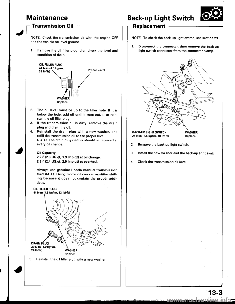
NOTE: Check the transmission oil with the engine OFF
and the vehicle on level ground.
1. Remove the oil filler plug, then check the level and
condition of the oil.
OIL FILLER PLUG44 N.m {4.5 kgf.m,Proper Level33 tbf.ftl
The oil level must be up to the filler hole. lf it is
below the hole, add oil until it runs out, then rein-
stall the oil filler plug.
lf the transmission oil is dirty, remove the drainplug and drain the oil.
Reinstall the drain plug with a new washer, and
refillthe transmission oilto the proper tevet.
NOTE: The drain plug washer should be replaced at
every oil change.
Oil Capacity
2.2 | i.2.3 US.qr,1.9 lmp.qtl at oil ch.nge.
2.3 t l2.1US.qt,2.O lmp.qtl at ovorhaul.
Always use genuine Honda manual transmission
fluid (MTF). Using motor oil can causa€tiffer shift-
ing because it does not contain the proper addi-
Back-up Light Switch
Replacement
NOTE: To check the back-up light switch. see section 23.
1. Disconnect the connector, then remove the back-up
light switch connector from the connector clamp.
l.m {2.5 kgf.m, 18lbf.ft) Replace.
Remove the back-up light switch.
Install the new washer and the back-up light switch.
Check the transmission oil level.
!ves.
OIL FILLER PLUG
DRAIN PLUG39 N.m {4.0 kg{.m,29 rbf.ftlReplace.
5. Reinstall the oil filler plug with a new washer,
Replace.
EACK.UP LIGHT SWITCH25 N.m {2.5 kgf.m, 18 lbf.ft)
13.3
Page 420 of 1681
Description
\J
t{
{
14-3
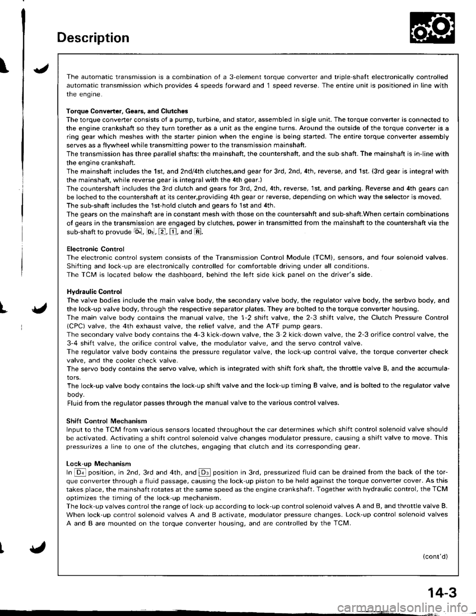
The automatic transmission is a combination of a 3-element torque converter and triple-shalt electronically controlled
automatic transmission which provides 4 speeds forward and 1 speed reverse. The entire unit is positioned in line with
the engrne.
Torque Converter, Gears, and Clutches
The torque converter consists of a pump, turbine, and stator, assembled in sigle unit. The torque converter is connected to
the engine crankshaft so they turn torether as a unit as the engine turns. Around the outside of the torque convener is a
ring gear which meshes with the starter pinion when the engine is being started. The entire torque converter assembly
serves as a flywheel while transmitting power to the transmission mainshaft.
The transmission has three parallel shafts; the mainshaft. the countershaft, and the sub shaft. The mainshaft is in-line with
the engine crankshaft.
The mainshaft includes the 1st, and 2ndl4th clutches,and gear for 3rd, 2nd, 4th, reverse, and 1st. (3rd gear is integral with
the mainshaft, while reverse gear is integral with the 4th gear.)
The countershaft includes the 3rd clutch and gears for 3rd,2nd, 4th, reverse, 1st, and parking. Reverse and 4th gears can
be loched to the countershaft at its center,providing 4th gear or reverse, depending on which way the selector is moved.
The sub-shaft includes the 1st-hold clutch and gears fo 1st and 4th.
The gears on the mainshaft are in constant mesh with those on the countersahft and sub-shaft.When certain combinations
of gears in the transmission are engaged by clutches. power in transmitted from the mainshaft to the countershaft via the
sub-shaft to orovude oil, lo'1. E, E. and E.
Electronic Control
The electronic control svstem consists of the Transmission Control Module (TCM), sensors, and four solenoid valves.
Shilting and lock-up are electronically controlled for comfortable driving under all conditions.
The TCM is located below the dashboard, behind the lelt side kick panel on the driver's side.
Hydraulic Control
The valve bodies include the main valve body, the secondary valve body, the regulator valve body, the serbvo body, and
the lock-up valve body, through the respective separator plates, They are bolted to the torque converter housing,
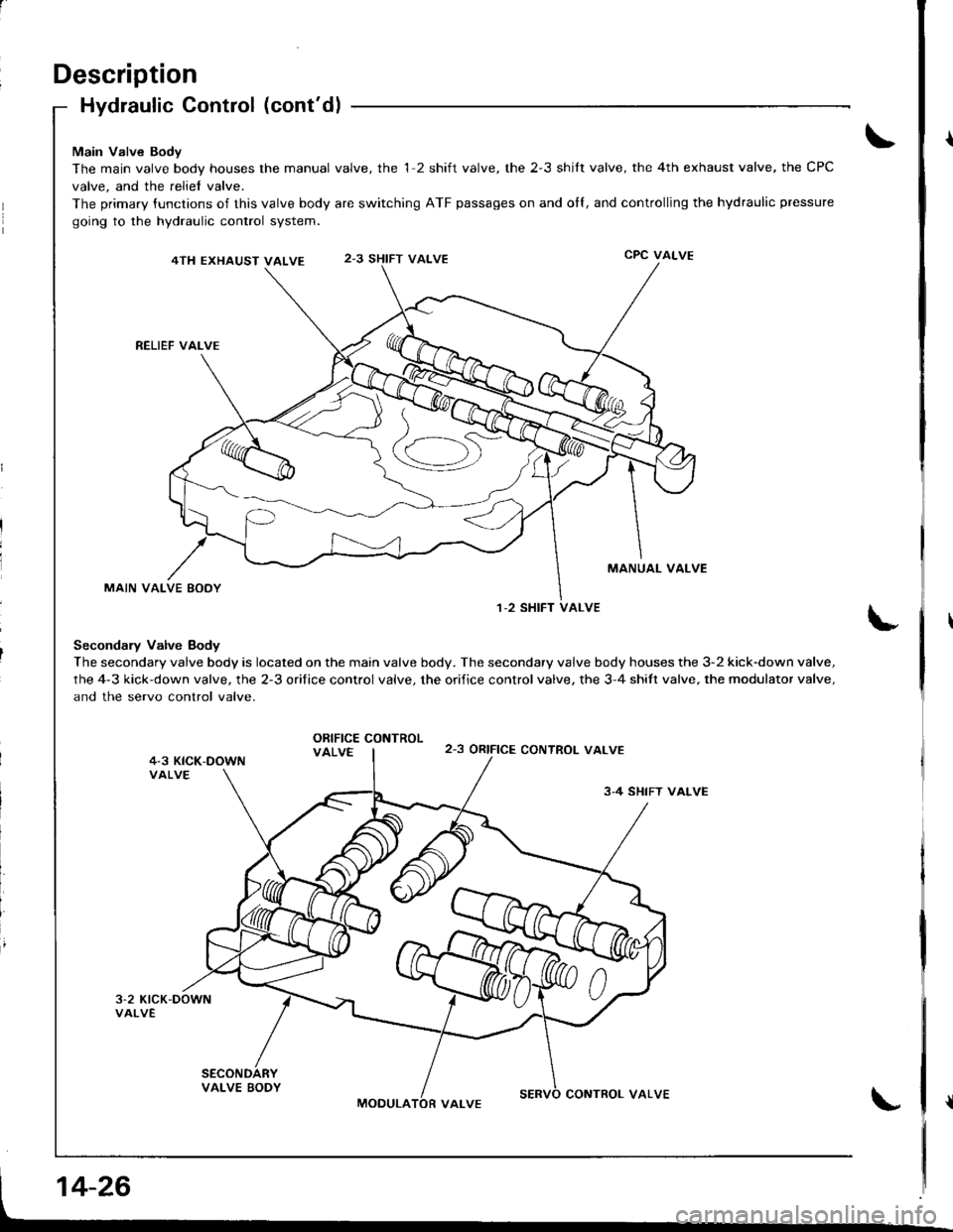
The main valve body contains the manual valve, the 1-2 shift valve, the 2-3 shitt valve, the Clutch Pressure Control
lCPC) valve, the 4th exhaust valve, the reliel valve, and the ATF pump gears.
The secondary valve body contains the 4-3 kick-down valve, the 3-2 kick-down valve, the 2-3 orifice control valve, the
3-4 shift valve, the orilice control valve, the modulator valve, and the servo control valve.
The regulator valve body contains the pressure regulator valve, the lock-up control valve, the torque converter check
valve, and the cooler check valve.
The servo body contains the servo valve, which is integrated with shift fork shaft, the throttle valve B, and the accumula-
tors.
The lock-up valve body contains the lock-up shift valve and the lock-up timing B valve, and is bolted to the regulator valve
ooqy.
Fluid from the regulator passes through the manual valve to the various control valves.
Shift Control Mechanism
Input to the TCM from various sensors located throughout the car determines which shift control solenoid valve should
be activated. Activating a shitt control solenoid valve changes modulator pressure, causing a shift valve to move. This
pressurizes a line to one ol the clutches, engaging that clutch and its corresponding gear.
Lock-uD Mechanism
In @ position, in 2nd, 3rd and 4th, and @ position in 3rd, pressurized fluid can be drained lrom the back oI the tor-
que converter through a fluid passage, causing the lock-up piston to be held against the torque converter cover. As this
takes place, the mainshaft rotates at the same speed as the engine crankshaft. Together with hydraulic control, the TCM
optimizes the timing of the lock-up mechanism.
The lock-up valves controlthe range of lock-up according to lock-up control solenoid valves A and B, and throttle valve B.
When lock-up control solenoid valves A and B activate, modulator pressure changes. Lock-up control solenoid valves
A and B are mounted on the torque converter housing, and are controlled by the TCM.
(cont'd)
Page 434 of 1681
ILB.l Position
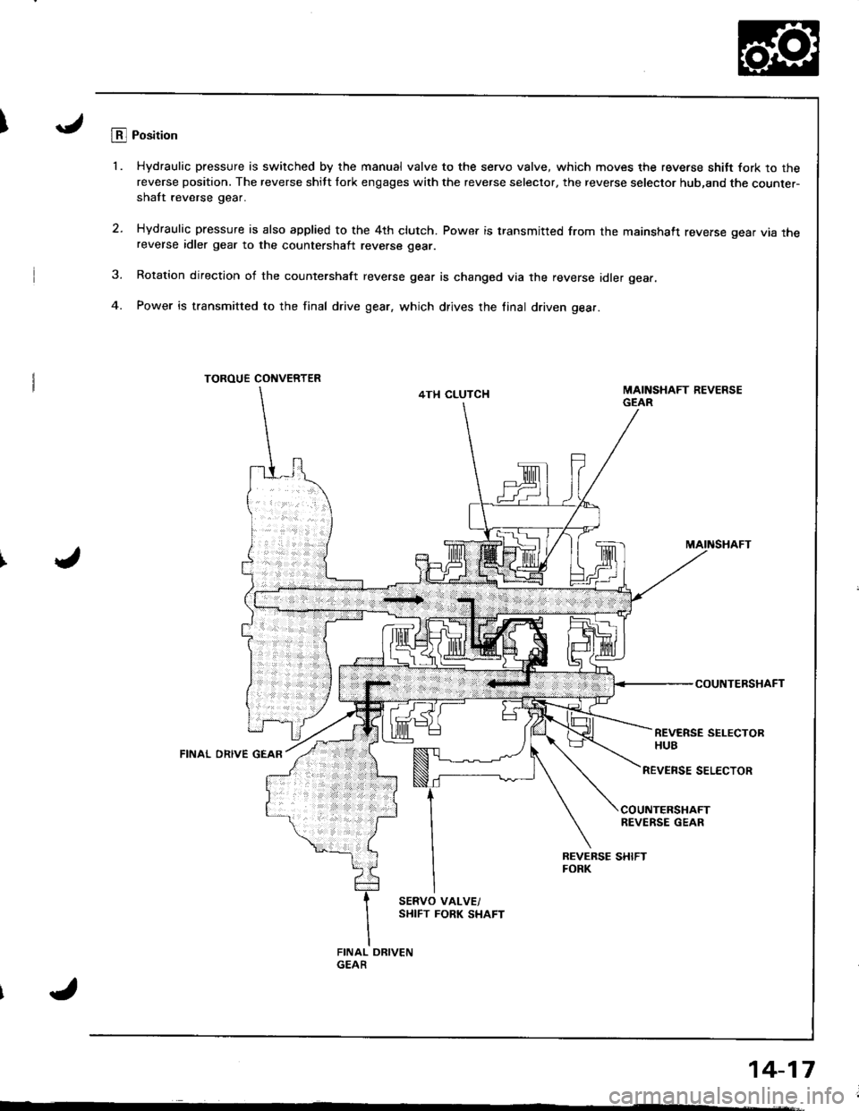
'1. Hydraulic pressure is switched by the manual valve to the servo valve, which moves the reverse shitt fork to thereverse position. The reverse shitt fork engages with the reverse selector, the reverse selector hub,and the counter-shaft reverse gear.
2. Hydraulic pressure is also applied to the 4th clutch. Power is transmitted from the mainshaft reverse gear vta rnereverse idler gear to the countershalt reverse gear.
3. Rotation direction of the countershaft reverse gear is changed via the reverse idler gear.
4. Power is transmitted to the final drive gear, which drives the linal driven gear.
TOROUE CONVERTER
4TH CLUTCH
MAINSHAFT
COUNTERSHAFT
REVERSE SELECTORHUBFINAL ORIVE GEAR
REVENSE SELECTOR
COUNTERSHAFTREVERSE GEAR
Page 440 of 1681
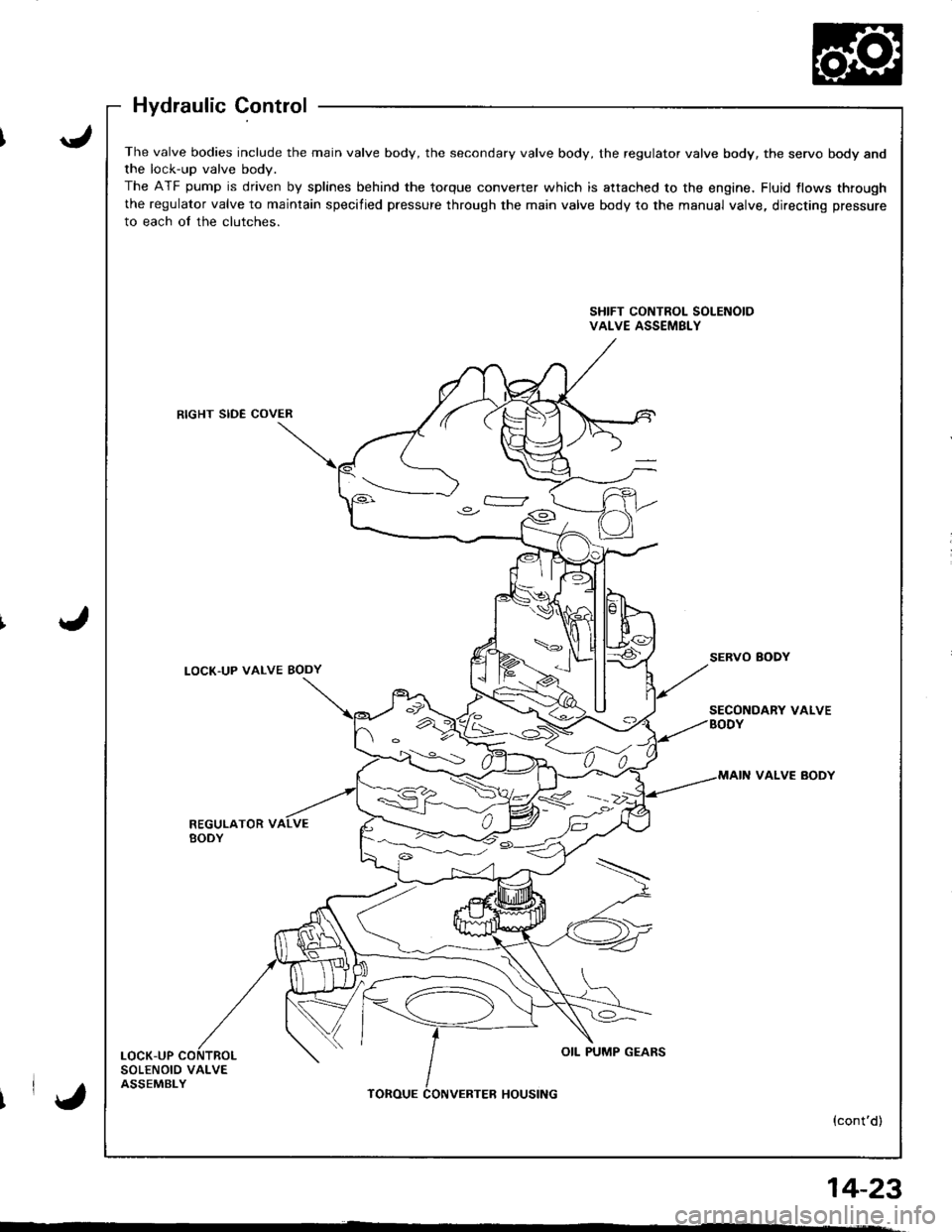
The valve bodies include the main valve body, the secondary valve body, the regulator valve body, the servo body andthe lock-up valve bodv.
The ATF pump is driven by splines behind the torque converter which is attached to the engine, Fluid {lows through
the regulator valve to maintain specified pressure through the main valve body to the manual valve, directing pressure
to each of the clutches.
SHIFT CONTROL SOLENOIDVALVE ASSEMBLY
RIGHT SIDE COVER
LOCK'UP VALVE BODYSERVO BODY
SECONDARY VALVEBODY
VALVE BODY
REGULATOR VBODY
LOCK-UPOIL PUMP GEARS
SOLENOID VALVEASSEMBLYTOROUEHOUSING
{cont'd)
%<->--::/ )C)
IrY,
14_23
'
Page 443 of 1681
Description
Hydraulic Control (cont'dl
Main Valve Body
The main valve body hous€s the manual valve, the 1 2 shift valve, the 2-3 shilt valve, the 4th exhaust valve, the CPC
valve, and the reliel valve.
The primary {unctions of this valve body are switching ATF passages on and olf, and controlling the hydraulic pressure
going to the hydraulic control system.
4TH EXHAUST VALVE2-3 SHIFT VALVECPC VALVE
RELIEF VAI-VE
MANUAL VALVE
MAIN VALVE EODY
Secondary Valve Body
The secondary valve body is located on the main valve body. The secondary valve body houses the 3-2 kick-down valve,
the 4-3 kick-down valve, the 2-3 orifice control valve, the orifice control valve. the 3-4 shitt valve, the modulator valve,
and the servo control valve.
ORIFICE CONTROLVALVE2-3 oRtFtCE CONTROT_ VALVE
3-4 SHIFT VALVE
1-2 SHIFT VALVE
MOOULACONTROL VALVE
Page 445 of 1681
Description
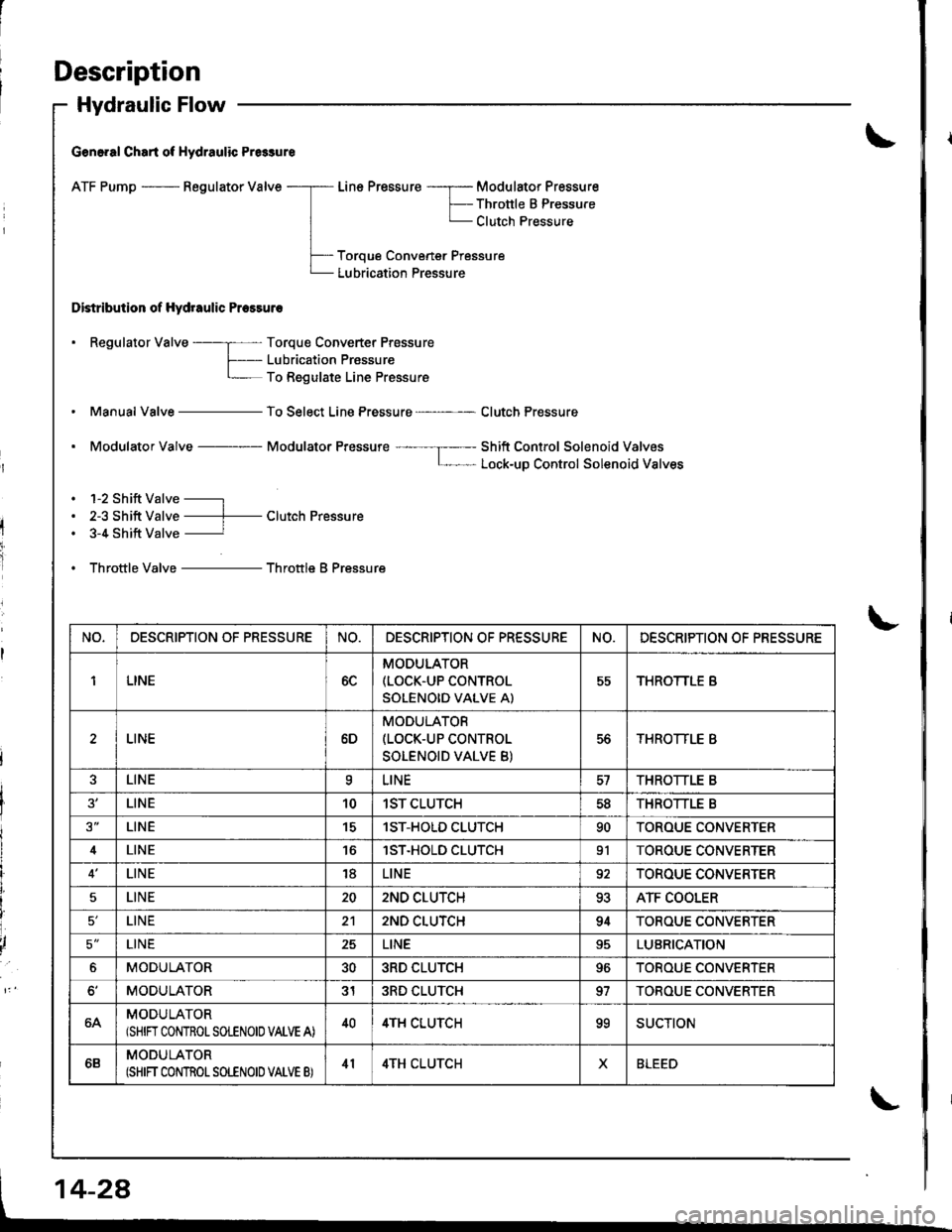
Hydraulic Flow
G€n6.al Chart of Hydraulic Pr6sure
ATF Pump - Regulator Valve
Distribution of Hydraulic Pressuro
Line Pressure -----r- Modulator Pressure
F-- Thronle B PressureL Clutch Pressure
Toroue Convener Pressure
Lubrication Pressure
. Regulator Valve ----; Torque Converter Prossure
f- Lubricaiion PrassureL To Regulate Line Pressure
Manual Valve - To Select Line Pressure - Clutch Pressure
. Modulator Valve Modulator Pressure ---- --I----- Shift Control Solenoid ValvosL- Lock-uD Control Solenoid Valves
. 1-2 Shift Valve -----l
. 2-3 Shift Valve ----f- Clutch Pressure. 3-4 Shift Valve ----------r
. Throttle Valve - Throttle B Pressure
NO,DESCRIPTION OF PRESSURENO.DESCRIPTION OF PR€SSURENO.DESCRIPTION OF PRESSURE
1LINE6C
MODULATOR(LOCK.UP CONTROL
SOLENOID VALVE A)
55THROTTLE B
LINE6D
MODULATOR(LOCK-UP CONTROL
SOLENOID VALVE B)
56THROTTLE B
LINEaLINETHROTTLE B
LINE101ST CLUTCH5dTHROTTLE B
LINE151ST-HOLD CLUTCH90TOROUE CONVERTER
4LINElST.HOLD CLUTCH91TOROUE CONVERTER
LINE18LINE92TOROUE CONVERTER
5LINE202ND CLUTCH93ATF COOLER
LINE212ND CLUTCH94TOROUE CONVERTER
5'LINE25LINELUBRICATION
6MODULATOR303RD CLUTCH96TOROUE CONVERTER
MODULATOR313RD CLUTCH97TOBOUE CONVERTER
64MODULATOR(SHIN CONTROLSOLENOIO VALVE A)404TH CLUTCHooSUCTION
6BMODULATOR(SHIFT CONTROT SOLENOID VATVE B)414TH CLUTCHXBLEED
Page 447 of 1681
Description
Hydraulic Flow (cont'dl
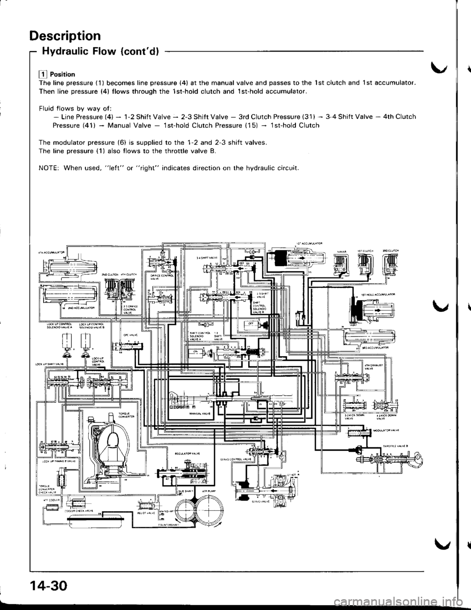
L! l Position
The line pressure ( 1 ) becomes line pressure (4) at the manual valve and passes to the 1st clutch and 1 st accumulator.
Then line pressure (4) llows through the 1st-hold clutch and 1st-hold accumulator.
Fluid flows bv wav of:- Line Pressure (4) - 1-2 Shift Valve - 2-3 Shitt Valve - 3rd Clutch Pressure (31) -- 3-4 Shift Valve - 4th Clutch
Pressure (41) - Manual Valve - lst-hold Clutch Pressure (15) - lsfhold Clutch
The modulator pressure (6) is supplied to the 1-2 and 2-3 shift valves.
The lane Dressure (1) also flows to the throttle valve B.
NOTE: When used, "left" or "right" indicates direction on the hydraulic ci.cuit.
14-30
Page 448 of 1681
LA Position
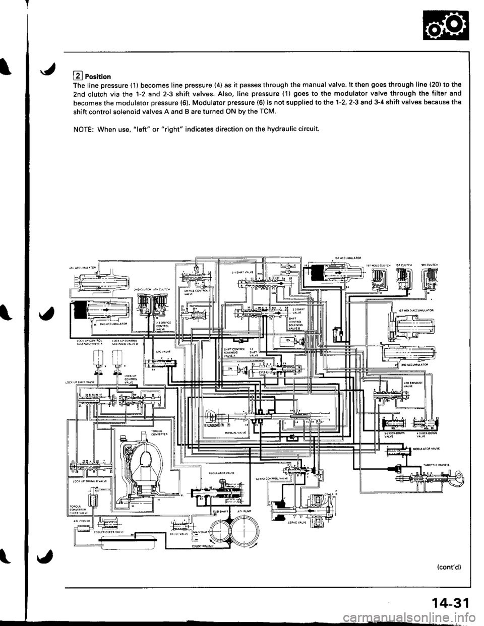
The line pressure (1) becomes line pressure (4) as it passes through the manual valve. lt then goes through line 120) to the
2nd clutch via the 1-2 and 2-3 shift valves. Also. line pressure (1) goes to the modulator valve through the filler and
becomes the modulator pressure (6). Modulator pressure (6) is not supplied to the 1-2. 2-3 and 3-4 shift valves because the
shift control solenoid valves A and B are turned ON bv the TCM.
NOTE; When use, "left" or "right" indicates direction on the hydraulic circuit.
(cont'd)
14-31
Page 452 of 1681
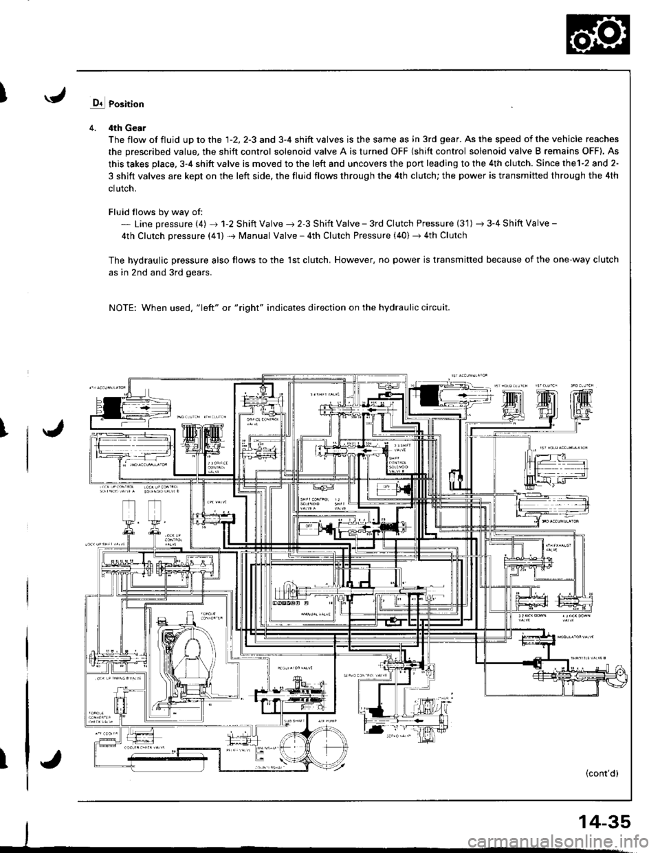
Iq1 Position
4. 4th Gear
The flow of fluid up to the 1-2, 2-3 and 3-4 shift valves is the same as in 3rd gear. As the speed of the vehicle reaches
the prescribed value, the shift control solenoid valve A is turned OFF (shift control solenoid valve B remains OFF). As
this takes place, 3-4 shitt valve is moved to the left and uncovers the port leading to the 4th clutch. Since thel-2 and 2-
3 shift valves are kept on the left side, the fluid flows through the 4th clutch; the power is transmitted through the 4th
clutch.
Fluid flows by way of:- Line pressure (4) + 1-2 Shift Valve ) 2-3 Shift Valve - 3rd Clutch Pressure (3'1) -t 3-4 Shift Valve -
4th Clutch pressure (41) + Manual Valve - 4th Clutch Pressure (40) + 4th Clutch
The hvdraulic pressure also flows to the 1st clutch, However, no power is transmitted because of the one-way clutch
as in 2nd and 3rd gears.
NOTE: When used, "1eft" or "right" indicates direction on the hydraulic circuit.
I
T(cont'd)
14-35
Page 453 of 1681
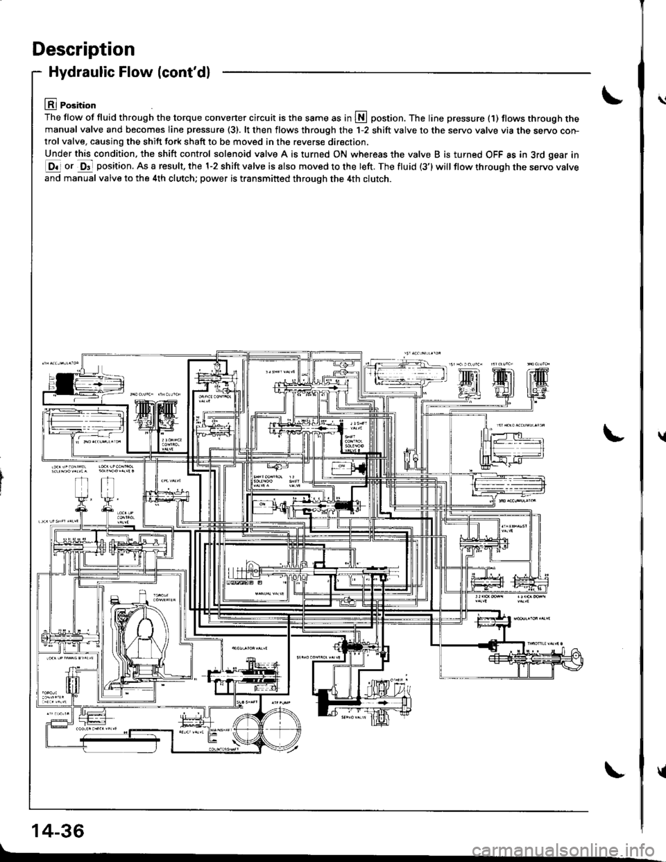
Description
Hydraulic Flow (cont'dl
lll Position
The flow of fluid th.ough the torque converter circuit is the same as in S postion. The line pressure (1) tlows through themanual valve and becomes line pressure (3). lt then flows through the 1-2 shift valve to the servo valve via the servo con-trol valve, causing the shift fork shaft to be moved in the reverse direction.
Under this condition, the shift control solenoid valve A is turned ON whereas the valve B is turned OFF as in 3rd gear in
E ot O"- position. As a result. the 1-2 shift valve is also moved to the left. The fluid (3') will flow through tne servo varve
and manual valve to the 4th clutch; power is transmitted through the 4th clutch.
14-36
\l
\
{
{