Manual HONDA INTEGRA 1998 4.G Owner's Guide
[x] Cancel search | Manufacturer: HONDA, Model Year: 1998, Model line: INTEGRA, Model: HONDA INTEGRA 1998 4.GPages: 1681, PDF Size: 54.22 MB
Page 1134 of 1681
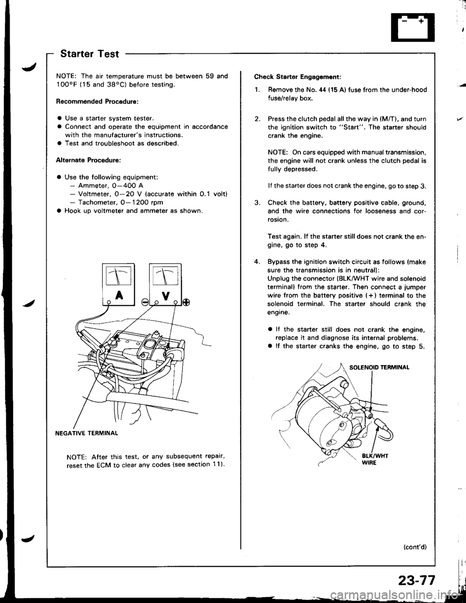
Ch6ck Starter Engag€mont;
1. Remove the No. 44 (15 A) fuse from the under-hood
fuse/relay box,
Press the clutch pedal all the way in (M/T), and turn
the ignition switch to "St8rt". The staner should
crank the engine,
NOTE: On cars equipped with manual transmission,
the engine will not crank unless the clutch pedal is
fully depressed.
lf the starter does not crank the engine, go to step 3.
Check the battery, battery positive cable, ground,
and the wire connections for looseness and cor-
rosion.
Test again. lf the stsner stilldoes not crank the en-
gine, go to step 4.
Bypass the ignition switch circuit as follows {make
sure the transmission is in neutral)
Unplug the connector (BLKMHT wire and solenoid
terminal) trom the staner. Then connect a jumper
wire from the batterv positive (+ ) terminal to the
solenoid terminal. The starter should crank the
engine.
a It the stsrter still does not crank the engine,
replace it and diagnose its internal problems,
a lf the starter cranks the engine. go to step 5.
(cont'd)
4.
NOTE: The air temperature must be between 59 and
100oF {15 and 38'C) betore testing.
Recommended Procedure:
a Use a starter system tester.
a Connect and operate the equipment in accordance
with the manufacturer's instructions.
a Test and troubleshoot as described.
Alternate Procodure:
a Use the following equipment;- Ammeter, O-400 A- Voltmeter. O-20 V (accurate within O,1 volt)- Tachometer, O- 1 2OO rpm
a Hook up voltmeter and ammeter as shown.
NEGATIVE TERMINAL
NOTE: Atter this test, or any subsequent repalr,
reset the ECM to clear any codes (see section 1 1).
StartelTest
23-77
Page 1135 of 1681
Starting System
Starter Test (cont'dl
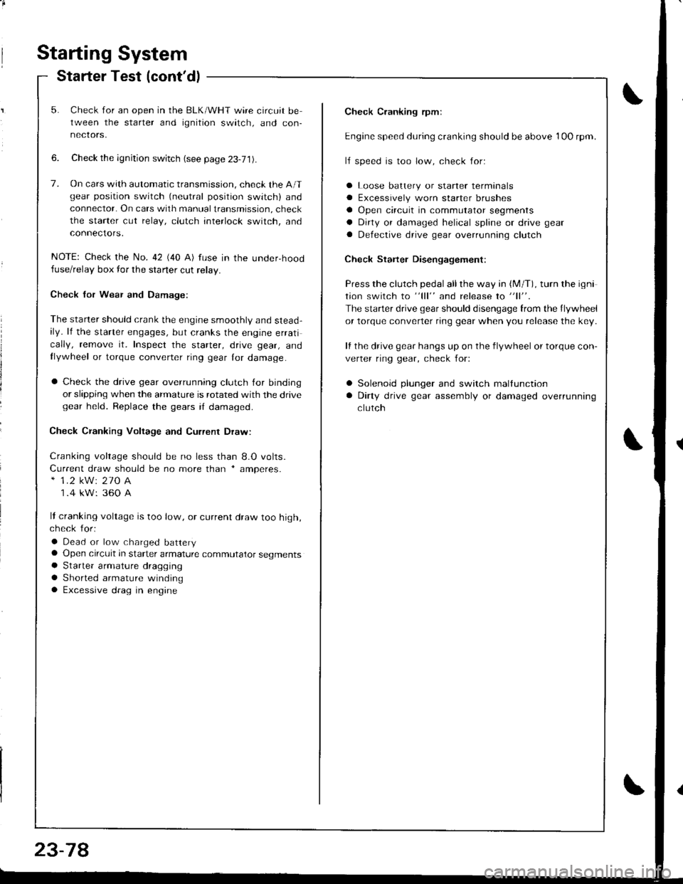
Check Cranking rpmr
Engine speed during cranking should be above 1OO rpm.
lJ speed is too low, check for:
a Loose batlery or starter terminals
a Excessively worn starter brushes
a Open circuit in commutator segments
a Dirty or damaged helical spline or drive gear
a Defective drive gear overrunning clutch
Check Starter Disengagement:
Press the clutch pedal all the way in (M/T), turn rhe igni
tion switch to "lll" and release to "11".
The starter drive gear should disengage from the flywheel
or torque converter ring gear when you release the key.
It the drive gear hangs up on the flywheel or torque con-
verter ring gear, check for:
a Solenoid plunger and switch mallunction
a Dirty drive gear assembly or damaged overrunning
clutch
5. Check for an open in the BLK/WHT wire circuit be
tween the starter and ignition switch, and con-
necrors,
6. Check the ignition switch (see page 23-71).
7. On cars with automatic transmission, check the A/Tgear position switch (neutral position switch) and
connector. On cars with manualtransmission, check
the starter cut relay, clutch interlock switch, and
connectors.
NOTE: Check the No. 42 (40 A) fuse in the under,hoodfuse/relay box for the starter cut relay.
Check Jor Wear and Damage:
The starter should crank the engine smoothly and stead,ily. lf the starter engages, but cranks the engine errati
cally, remove it. Inspect the starter, drive gear, andllywheel or torque converter ring gear lor damage.
a Check the drive gear overrunning clutch for binding
or slipping when the armature is rotated with the drivegear held. Replace the gears i{ damaged.
Check CJanking Voltage and Current Draw:
Cranking voltage should be no less than 8.O volts.
Current draw should be no more than * amperes.* 1.2 kW: 27O A
1 .4 kW: 360 A
It cranking voltage is too low, or current draw too high,check for:
a Dead or low charged batterya Open circuit in starter armature commutator segmentsa Starter armalure dragging
a Shorted armature windinga Excessive drag in engine
Page 1245 of 1681
Back-up Lights
Test
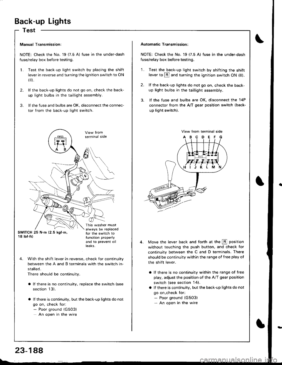
Manual Transmission:
NOTE: Check the No. 19 (7.5 A) fuse in the underdash
fuse/relay box before testing.
Test the back-up light switch by placing the shift
lever in reverse and turning the ignition switch to ON
fl r).
lI the back-up lights do not go on, check the back-
up light bulbs in the taillight assembly.
lI the fuse and bulbs are oK, disconnect the connec-
tor from the back-up light switch.
2.
3.
l.
SWITCH 25 N.m (2.5 kgf-m,'18 lbf-Ir)
This washer mustalways be replacedfor the switch totunction properly
and 10 prevent oilteaKs,
terminal side
4. With the shift lever in reverse, check for continuity
between the A and B terminals with the switch in-
stalled.
There should be continuity.
a It there is no continuity, replace the switch (see
section 13).
a lf there is continuity, but the back-up lights do not
go on, check for:- Poor ground {G503}
An open in the wire
A
6
Automatic T.ansmission:
NOTE: Check the No. 19 (7.5 A) fuse in the under-dash
fuse/relay box before testing.
2.
'1 .Test the back-up light swirch by shifting the shiftlever to @ and turning the ignition switch ON (ll).
lf the back-up lights do not go on, check the back-
up light bulbs in the taillight assembly.
lf the fuse and bulbs are OK, disconnect the 14P
connector from the A,/T gear position switch (back-
up light switch).
View from terminal side
ABCDEFG
Move the lever back and torth at the E position
without touching the push button, and check for
continuity between the C and D terminals. There
should be continuity within the range of free play of
the shilt lever.
a lf there is no continuity within the range of free
play, adiusl the position ot the A/T gear position
switch {see section 14}.
a lf there is continuity, but the back-up lights do not
go on,check tor:- Poor ground {G5O3)- An open in the wire
Page 1384 of 1681
)
)
How To Use This Manual
The next few pages describe how this manual is organized. They also
exolain what kind of information the manual contains, what that
information means, and how to use it to troubleshoot electrical problems.
Circuit schemalics break the entire electrical system into individual
syslems, like the Low Fuel Indicator Light on the next page.
Only electrical components that work together are shown together,
so you won't be distracted by unrelated wires.
Explanations of the abbreviations and symbols used in the schematics
begin on page E. You'll need to know what they mean before you can use
a schematic effectively.
Page 1385 of 1681
How To Use This Manual
Circuit Schematics
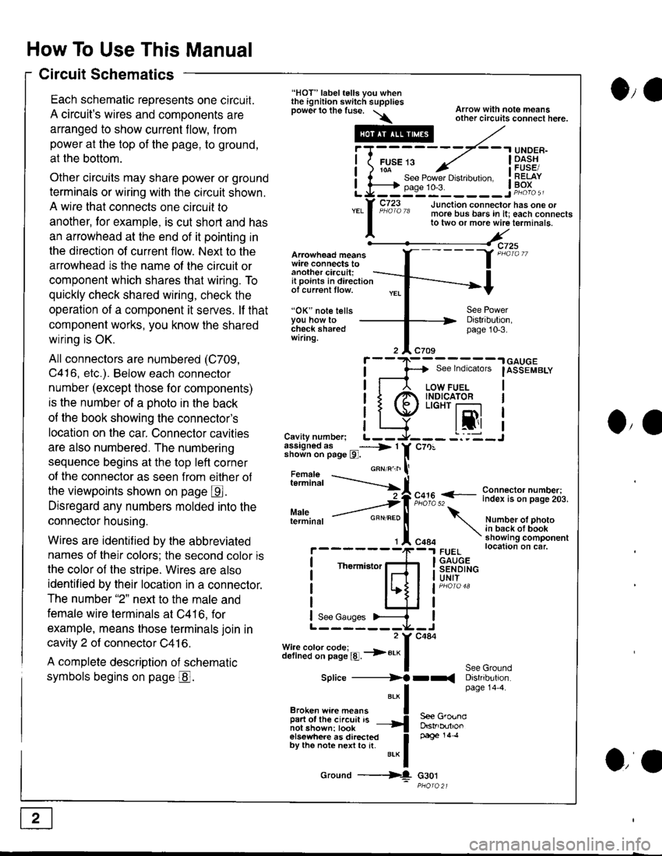
Each schematic reoresents one circuit.
A circuit's wires and components are
arranged to show current flow, from
power at the top of the page, to ground,
at the bottom.
Other circuits may share power or ground
terminals or wiring with the circuit shown.
A wire that connects one circuit to
another, lor example, is cut short and has
an arrowhead at the end of it pointing in
the direction of current flow. Next to the
arrowhead is the name ol the circuit or
component which shares that wiring. To
quickly check shared wiring, check the
operation of a component it serves. lf that
component works, you know the shared
wiring is OK.
All connectors are numbered (C709,
C416, etc.). Below each connector
number (except those for components)
is the number of a ohoto in the back
of the book showing the connector's
location on the car. Connector cavities
are also numbered. The numbering
sequence begins at the top left corner
of the connector as seen from eilher of
the viewpoints shown on page E.
Disregard any numbers molded into the
connector housing.
Wires are identif ied by the abbreviated
names of their colors; the second color is
the color of the stripe. Wires are also
identif ied by their location in a connector.
The number "2" next to the male and
female wire terminals at C416, for
example, means those terminals join in
cavity 2 of connector C41 6.
A complete description of schematic
symbols begins on page @.
O,e
Arowhead meanswire connects toanother ciacuit;it points in directionof current tlow.
"OK" note tellsYou how tocheck sharedwiring.
"HOT" label tells you whenthe ignition switch suppliesDower lo the fuse. \\
.---#
"*l
Broken wi.e means I
ffir"i:'ffi:[:l''" -{
elsewhere as directed Ioy ttt" not" n"n to [. u.* f
Ground ---{
Arrow with note meansother circuits connect here.
Distribution,page 10-3.
See lndicators
I
.| GAUGE
IASSEMBLY
I
I
I
IJO,'
i"?*i,h -..--.-{[
Cavity number; L--assigned as _----> 1shown on page l9l.
Maleterminal
c70!
F,":,2 f
- i":!f $l ?:T"'i,.i,.
Number ot photoin back ot bookshowing componentlocation on car.FUELGAUGESENDINGUNIT
See GroundDistribution.page 14'4.
c484
Thermistor
See Gauges
Splice ----------)f rr(
S€e GroundDstrb(rtlonpage 14 .l
G30t
iT;
Li=
- -.I UNDER-
FUsE 13 ../ I -Dl^s!io-a-- - , iFUsESee Power Drstlbulton. I RELAYpase 1o-3. ! Po^{^ -__:_____ ___Jp"otoa
o,a
Page 1387 of 1681
How To Use This Manual
Power Distribution Schematics
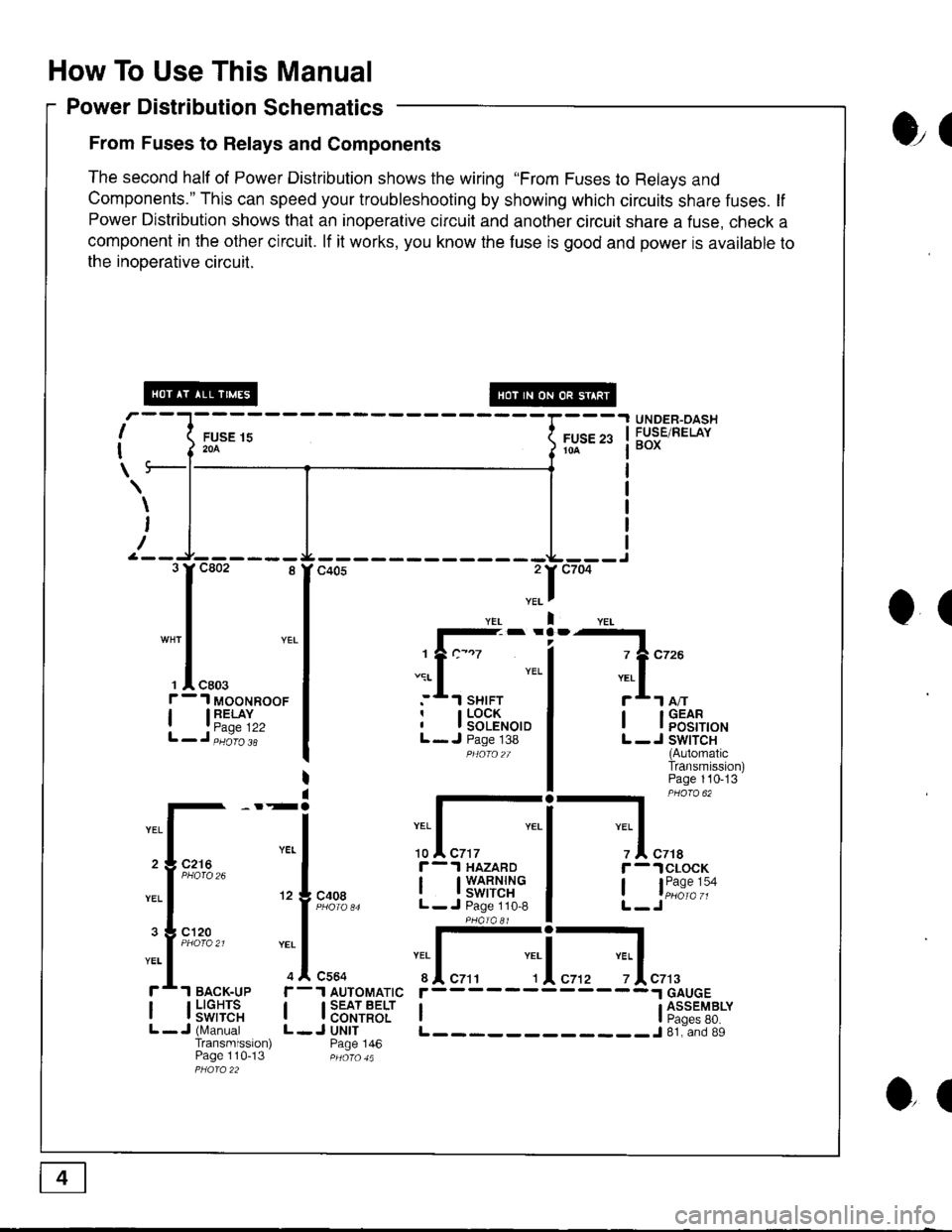
From Fuses to Relays and Components
The second half of Power Distribution shows the wiring "From Fuses to Relays and
Components." This can speed your troubleshooting by showing which circuits share fuses. lf
Power Distribution shows that an inoperative circuit and another circuit share a fuse, check a
component in the other circuit. lf it works, you know the fuse is good and power is available to
the inooerative circuil.
ol
I
I
\
FUSE 15204
UNDER-OASHFUSE/RELAYBOXFUSE 2310A
\
I
/
O(
.II
l-- -
1?c-.7
.:r- I YEL
:*.l sHrFTr I LOCKI I SOLENOIDL- J Page 138PHOfO2T
I lFEt[,o'
L -J SWITCH(AutomaticTransmission)Page 110-13
-l PHaro 62
IYEL Iz I czrar -.lclocK
, l"i1:"':oL-Jc408
r-.l HAZARD
I t3'S[t''i"L- J Page 110,8
:I-c564
1 AUTOMATIC
I SEAT BELTI CONTROLJ UNITPage 146
YEI
r
IL
c7t3
I l5"f,TE'"L -J (N,4anualTransmission)Page 110-13
r------
I ti:*'"T8*L____________J 81. and 89
3rc802 8
I
"* | YEL
I
', I "ro.f - 1 MooNRooF
| 13"'^TI",L-J,iiio'i'
2 3 C216
3 g cl20
ol
Page 1389 of 1681
How To Use This Manual
Component Locations
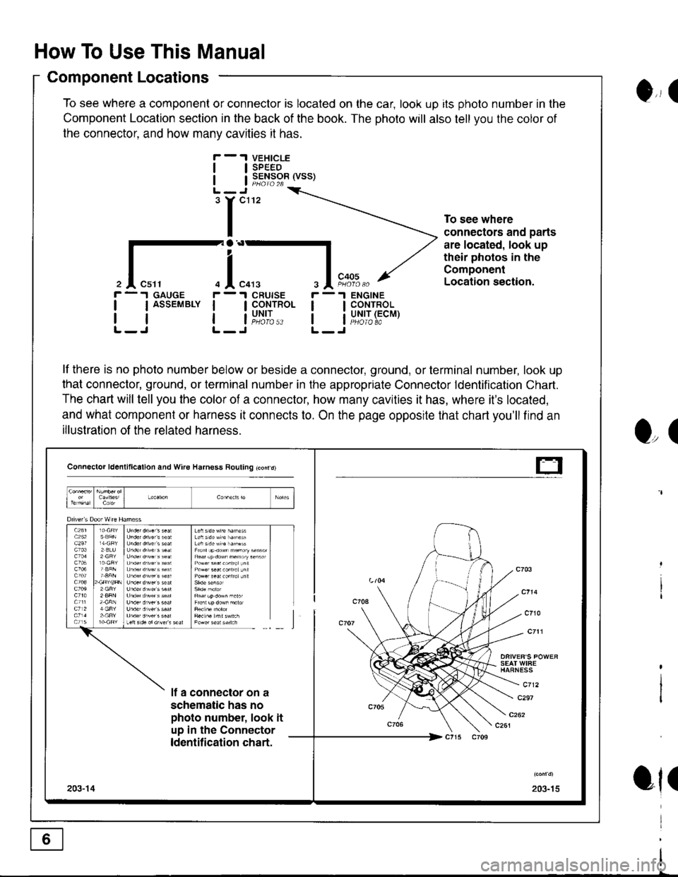
To see where a component or connector is located on the car, look up its photo number in the
Component Location section in the back of the book. The photo will also tell you the color of
the connector. and how manv cavities it has.
VEHICLESPEEDSENSOR (VSS)
ENGINECONTROLUNIT (ECMPHOIO 8A
0,, I
tl
tl
'r"'
To see where
connectors and parts
are located, look up
their photos in the
Component
Location section.
r -.I GAUGE
| | ASSEMBLY I
rtlL-J L-
r -'l
ll
ll
O,(
ot(
il"l,*.I CRUISE
I CoNTROL
i"u,t',:..
lf there is no photo number below or beside a connector, ground, or terminal number, look up
that connector, ground, or terminal number in the appropriate Connector ldentification Chart.
The chart will tell you the color of a connector, how many cavities it has, where it's located,
and what component or harness it connects to. On the page opposite that chart you'll find an
illustration of the related harness.
Connector ld6nlillcallon and Wire Harness Rouling tconrd)
SEAT WIFEHAFNESS
c712lf a connector on a
schematic has no
photo number, look it
up in the Connector
ldentification chart.
c297
203-15203-14
t-
Page 1391 of 1681
How To Use This Manual
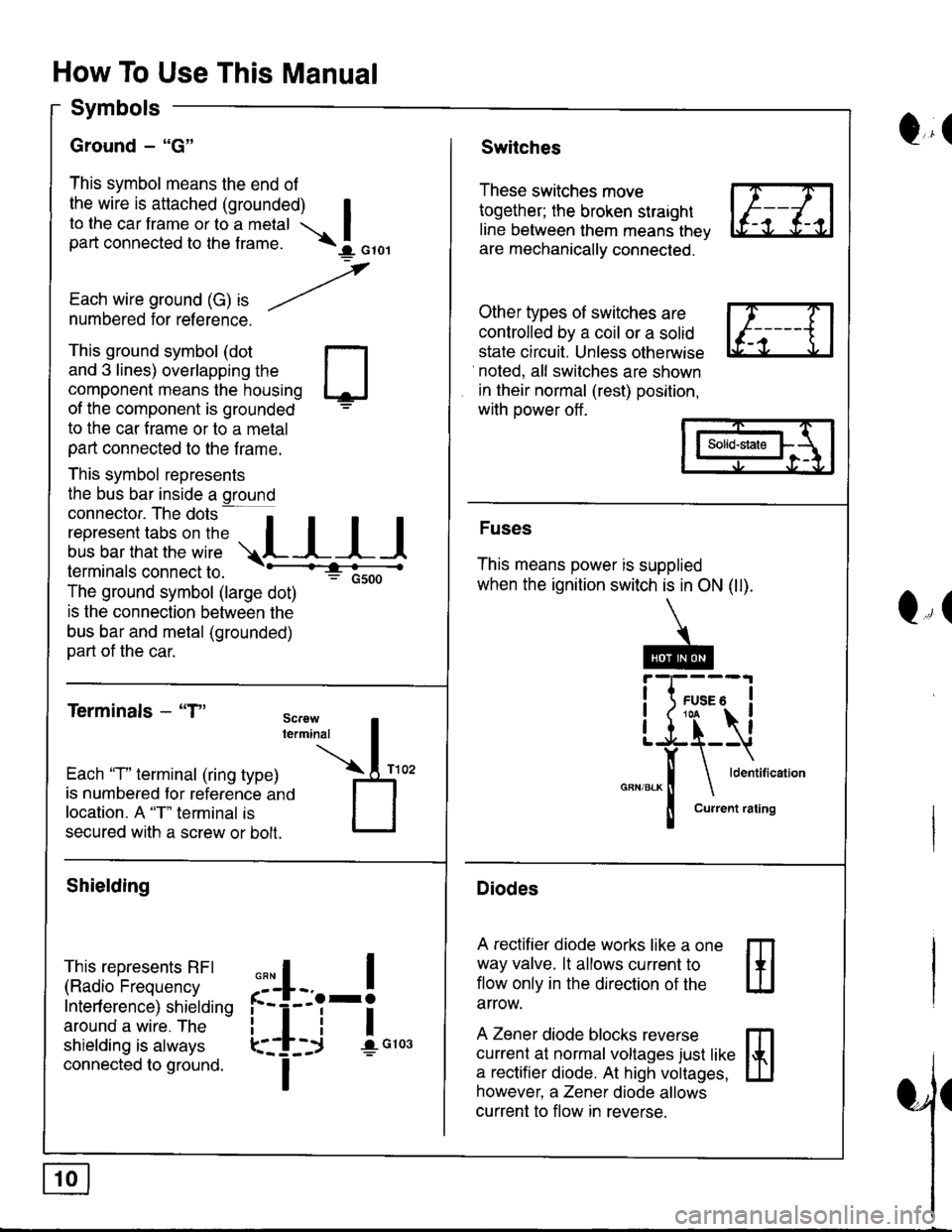
Symbols
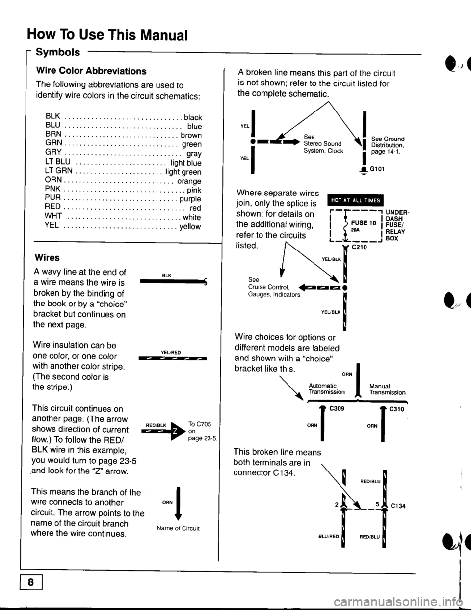
Q,(Wire Color Abbreviations
The following abbreviations are used to
identify wire colors in the circuit schematics:
BLK.... .........btack
BLU.... ......... btueBRN .... ........ brown
GRN.... ........ green
GRY .... ......... gray
LTBLU . ..... tighrbtue
LTGRN. ....ljghtgreen
ORN.... ....... orangePNK.... ..........pink
PUR .... ........ purpte
RED .... .......... redwHT... .,.......white
YEL .... ........ ye ow
A broken line means this part ot the circuit
is not shown; reler to the circuit listed for
the complete schematic.
",.I
ar
*.1
See GroundDistribution,page 14-1.
1G101
Where separate wires
join, only the splice is
shown; for details on
the additional wiring,
refer to the circuits
listed.i-l{:i
;["
UNDER.DASHFUSE/RELAYBOX
Wires
A wavy line at the end of
a wrre means the wire is
broken by the binding of
the book or by a "choice"
bracket but continues on
the next page.
Wire insulation can be
one color, or one color
with another color stripe.
(The second color is
the stripe.)
This circuit continues on
another page. (The arrow
shows direction of current
flow.) To follow the RED/
BLK wire in this example,
you would turn to page 23-5
and look for the "2" aftow.
This means the branch of the
wire connects to another
circuit. The arrow points to the
name of the circuit branch
where the wire continues.
BLK-Crulse Controt, QaalGauges, Indrcarors
!YEUBTK
II
Wire choices for options or
different models are labeled
and shown with a "choice"
This broken line means
both terminals are in
connector C134.
bracketlikethis
*J
Q,(
ManualTransmission
*'ffil:,*"1"' *"1""0
I
"""1
H
Name of Circuit
cl34
a,ll
Page 1393 of 1681
How To Use This Manual
Symbols
Ground - "G"
This symbol means the end of
the wire is attached (grounded) Ito the car frame or to a metal Ipart connected to the f rame. \I orol
,
Each wire ground (G) ," -/numbered for reference.
Q,(Switches
These switches move
together; the broken straight
line between them means thev
are mechanically connected.
Other types of switches are
controlled by a coil or a solid
state circuit. Unless otherwise
noted, all switches are shown
in their normal (rest) position,
with power off .
This ground symbol (dot
and 3 lines) overlapping the
component means the housing
of the component is grounded
to the car f rame or to a metal
part connected to the f rame.
This symbol represents
the bus bar inside a ground
connector. The dots a
i"r*"""*nn"l,':" .,.L I I I
lermtnals connectto. -'--'-:t"'--------<
The ground symbol (large dot)
: Gsoo
is the connection between the
bus bar and metal (grounded)
part of the car.
Terminals - "T"
m
ffi
Solid-state
Fuses
This means power is supplied
when the ignition switch is in ON (ll).
Diodes
A rectifier diode works like a one
way valve. lt allows current to
flow only in the dlrection of the
arrow.
A Zener diode blocks reverse
currenl at normal voltages just like
a rectifier diode. At high voltages,
however, a Zener diode allows
current to flow in reverse.
Q,(
Each 'T" terminal (ring type)
is numbered for reference ano
location. A "T" terminal is
secured with a screw or bolt.
Shielding
This represents RFI
(Radio Frequency
Interf erence) shielding
around a wire. The
shielding is always
connected to ground.
,,,
n
:'iL.-!
L-_+i !",*
I
Page 1395 of 1681
How To Use This Manual
Test Equipment
lf, in addition, you need to know exactly how
much resistance there is between two ooints.
use a digital volVohmmeter (DVOM).
In the "oHMS" range, the DVOM will show
resistance between two points along a circuit.
Low resistance means good continuity.
Diodes and solid-state devices in a circuit can
make a DVOM give a false reading. To check
a reading, reverse the leads, and take a
second reading. lf the readings differ, the
component is affecting the measurement.
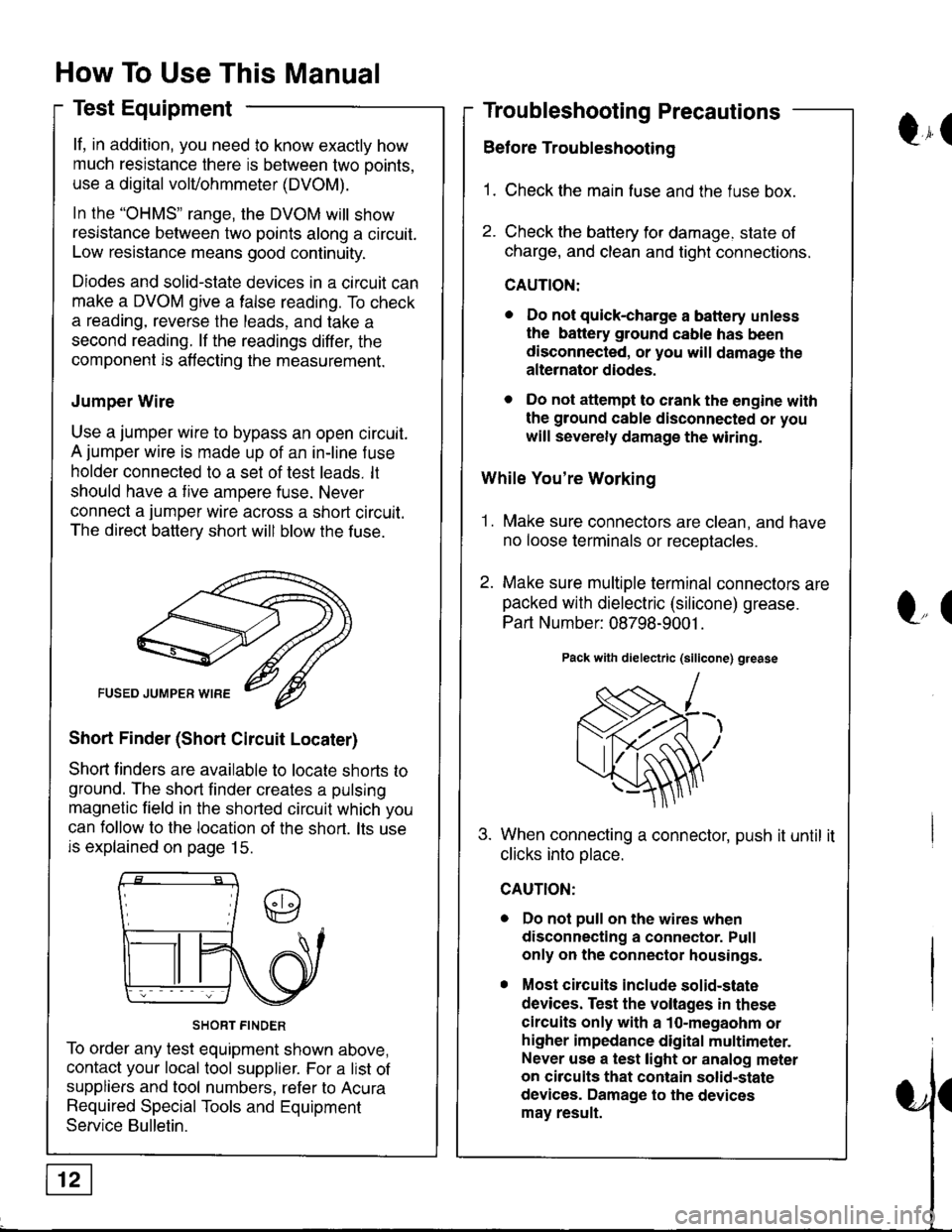
Jumper Wire
Use a jumper wire to bypass an open circuit.
A jumper wire is made up of an in-line f use
holder connected to a set of test leads. lt
should have a tive ampere fuse. Never
connect a jumper wire across a short circuit.
The direct battery short will blow the fuse.
Short Finder (Short Circuit Locater)
Shoft linders are available to locate shorts to
ground. The short finder creates a pulsing
magnetic field in the shorted circuit which you
can follow to the location of the short. lts use
is explained on page 15.
SHORT FINDER
To order any test equipment shown above,
contact your local tool supplier. For a list of
suppliers and tool numbers, refer to Acura
Required Special Tools and Equipment
Service Bulletin.
Troubleshooting Precautions
Before Troubleshooting
1. Check the main fuse and the fuse box.
2. Check the battery for damage. state of
charge, and clean and tight connections.
CAUTION:
. Do not quick-charge a battery unless
the battery ground cable has been
disconnected, or you will damage the
alternator diodes.
. Do not attempt to crank the engine with
the ground cable disconnected or you
will severely damage the wiring.
While You're Working
1. Make sure connectors are clean, and have
no loose terminals or receotacles.
2. Make sure multiple terminal connectors are
packed with dielectric (silicone) grease.
Part Number: 08798-9001 .
Pack with dielectric (silicone) grease
When connecting a connector, push it until it
clicks into olace.
Do not pull on the wires when
disconnecting a connector. Pull
only on the connector housings.
Most circuits include solid-state
devices. Test the voltages in these
circuits only with a 1o-megaohm or
higher impedance digital multimeter.
Never use a test light or analog meter
on circuits that contain solid-state
devices. Damage to the devices
may result.
Qr(
l"(