ground HONDA INTEGRA 1998 4.G Service Manual
[x] Cancel search | Manufacturer: HONDA, Model Year: 1998, Model line: INTEGRA, Model: HONDA INTEGRA 1998 4.GPages: 1681, PDF Size: 54.22 MB
Page 348 of 1681
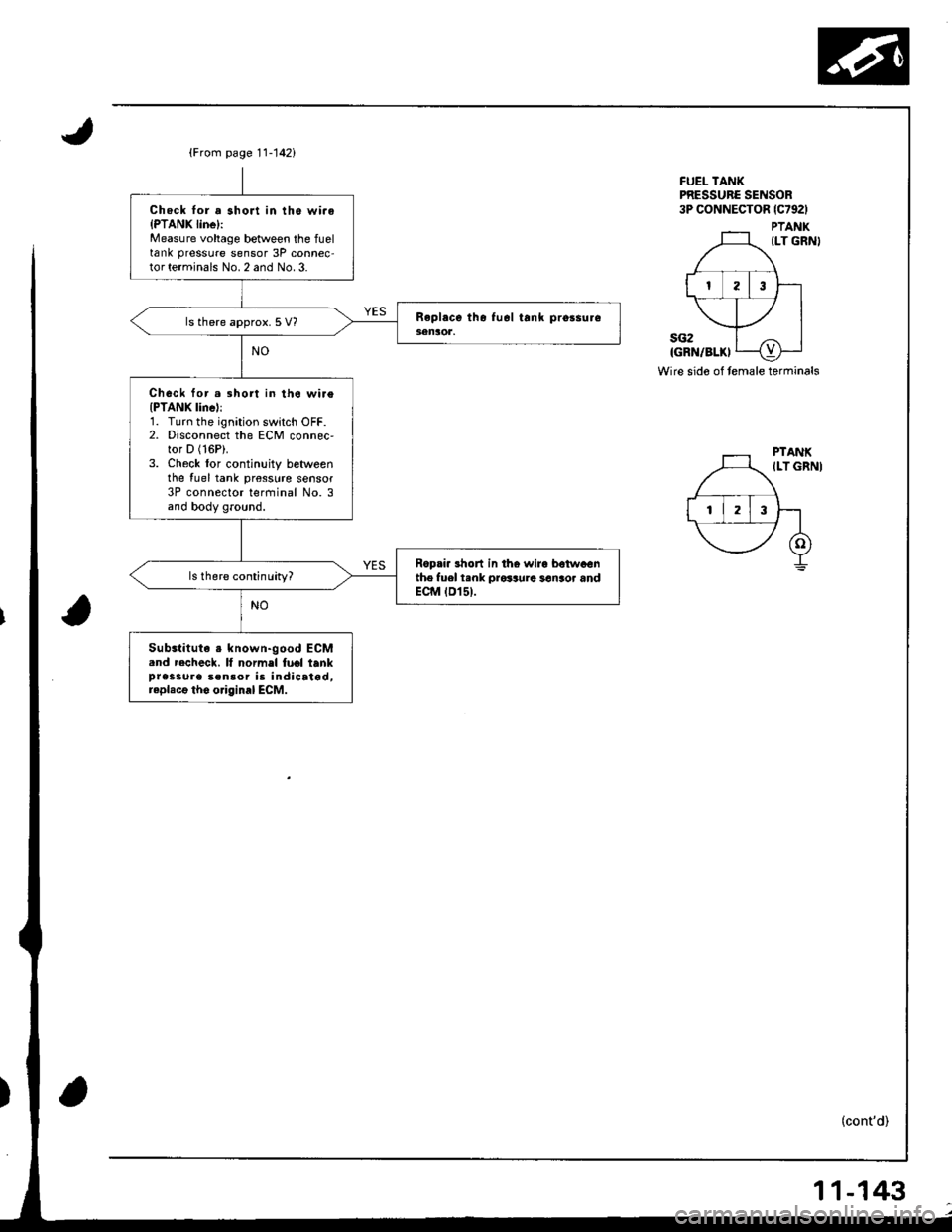
{From page 11-142i
Chock lor a short in tho wi.oIPTANK linel:Measure voltage between the fueltank pressure sensor 3P connec-tor terminals No. 2 and No. 3.
ls there approx. 5 V?
Chock for.3hort in th6 wi.e(PTANK lincl:1. Turn the ignition switch OFF.2. Disconnect the ECM connec,tor D (16P).
3. Check lor continuity betweenthe {uel tank pr€sslrre sensor3P connector terfiinal No. 3and body ground.
Ropri. 3hon in tho wira betwaGnthe fuel t.nk prosaura san3or andECM tD15t.
Substituta s known-good ECM.nd recheck. It normel fuel tenkpressure son30r is indicatod,raplacg tho o.iginal ECM.
FUEL TANKPRESSURC SENSOR3P CONNECTOR lc792l
PTANKILT GRN}
sG2IGRN/BLKI
Wire sido of temale terminals
(cont'd)
11-143
Page 349 of 1681
rI
Emission Control System
Evaporative Emission (EVAPI Controls (cont'd)
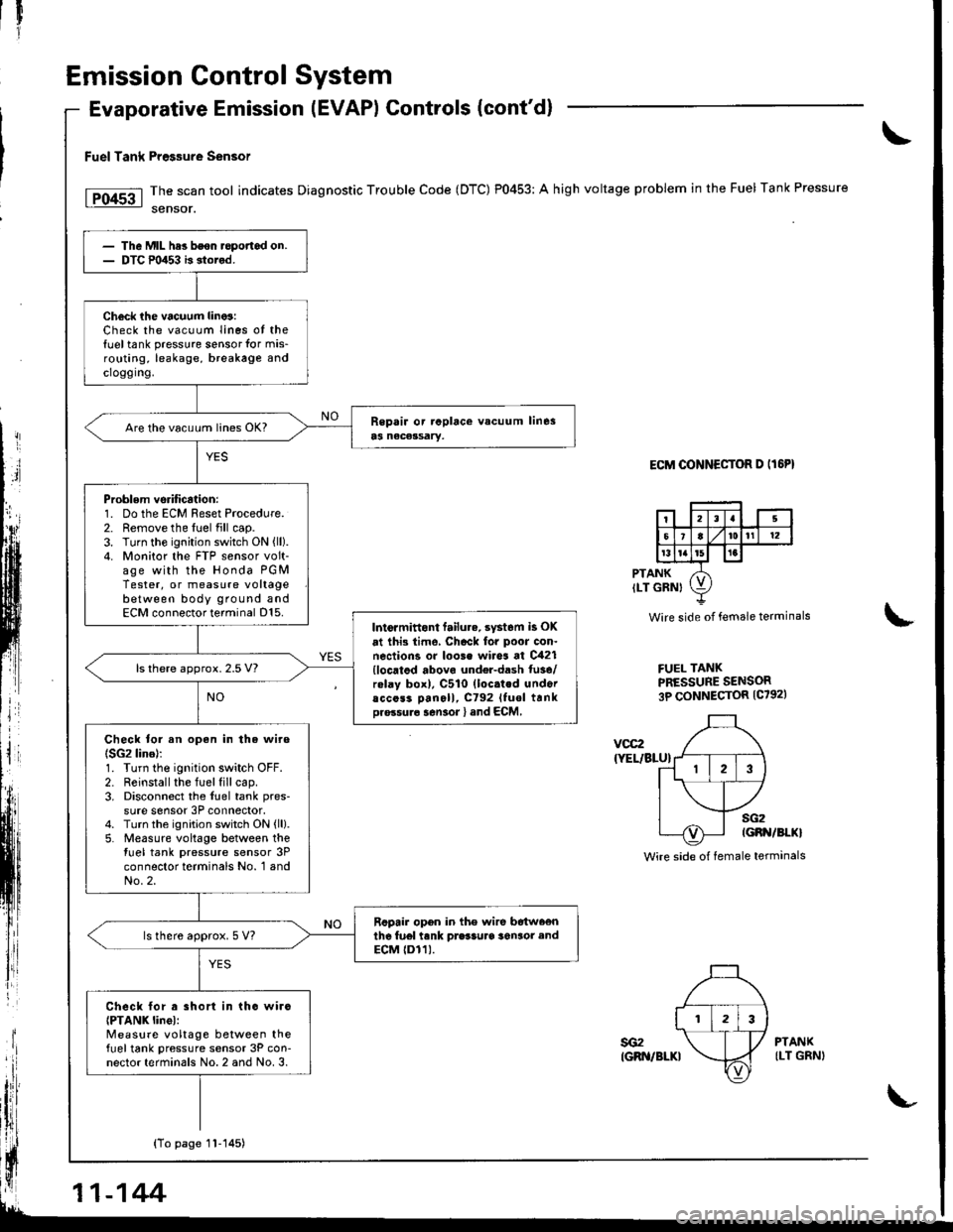
Fuel Tank Pre$ure sensor
The scan tool indicates Diagnostic Trouble Code (DTC) P0453: A high voltage problem in the Fuel Tank Pressure
sensor.
ECM OONNECTOR D IT6PI
PTANKILT GRNI
Wire side of female terminals
FUEL TANKPRESSURE SENSOR3P CONNECTOR {C7921
\
voc2
{YEL/BLU}
sG2IGBN/BI.KI
Wire side of female terminals
The Mll- hes bson.opofiad on.DTC m453 b stored.
Check ihe vacuum lino3:Check the vacuum Iines ot the{uel tank pressure sensor for mis-routing, leakage, breakage andcroggrng.
Are the vacu!m lin€s OK?
Problem vsrification:1. Do the ECM Reset Procedure.2. Remove the fuel fill cap.3. Turn the ignition switch ON {ll).4. Monitor the FTP sensor volt-age with the Honda PGMTester, or measure voltagebetween body ground andECM connector terminal D15.Intormittont failu.e. syst6m is OK
at ihi3 time, Chack for poor con.nections or loo3e wires at C421{locatod abovo undel-dash fu3e/rolay box), C510 (loc.ted undoracc6s3 Dan6ll, C792 Ituol trnkDro.su.6 sen3or l and ECM,
ls there approx. 2.5 V?
Check tor an open in the wire(SG2 lino):1. Turn the ignition switch OFF.2. Reinstall the fuel fill cap.3. Disconnect the fuel tank pres-
sure sensor 3P connector.4. Turn the ignition switch ON {ll}.5. Measure voltage between thetuel tank pressure sensor 3Pconnector terminals No. 1 andNo.2.
Rcpair opon in the wire b6tw66nthe fu6l tank prasSuaa 36n3or endECM {Dr1).ls there approx. 5 V?
Check lor a short in tho wirc{PTANK linel:Measure voltage between thefueltank pressure sensor 3P con-nector terminals No. 2 and No. 3.
YES
sG2IGRN/BLKI
PTANKILT GRNI
{To page 1l-145)
11-144
Page 351 of 1681
Il
1l
Iil
Emission Control SYstem
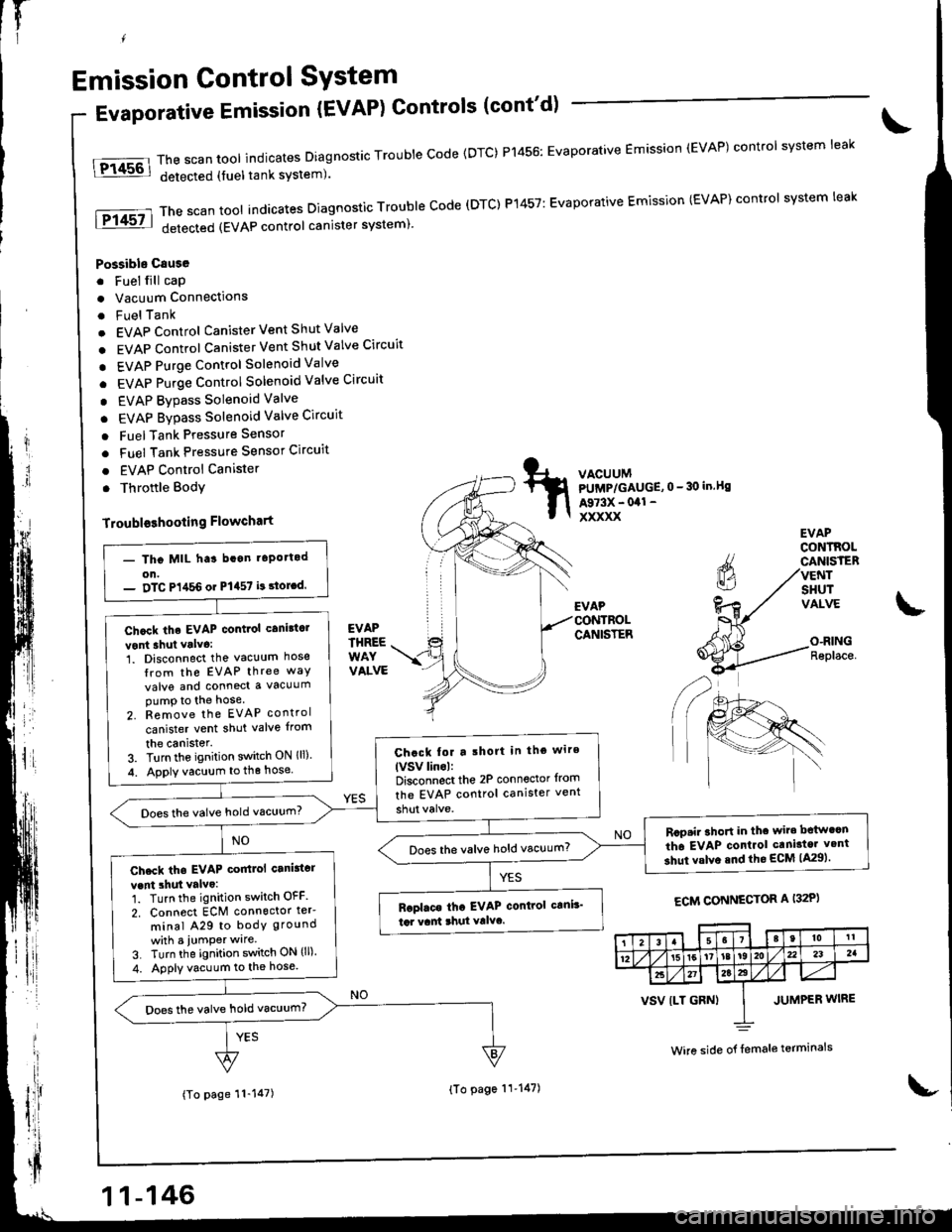
EVAPrHREEWAYVALVE
tFi4s6l
fPf 45? I
Evaporative Emission {EVAP) Controls (cont'd)
Possible Csuse
. Fuel fill cap
. Vacuum Connections
. FuelTank
. EVAP Control Canister Vent Shut Valve
. EVAP Control Canister Vent Shut Valve Circuit
. EVAP Purge control Solenoid Valve
. EVAP Purge Control Solenoid Valve Circuit
. EVAP Bypass Solenoid Valve
. EVAP Bypass Solenoid Valve Circuit
o FuelTank Pressure Sensor
. Fuel Tank Pressure Sensor Circuit
. EVAP Control Canister
. Throftle Body
Troubloshooling Flowchart
The scan tool indicates Diagnostic Trouble Code {DTC) P1456: Evaporative Emission (EVAP) control system leak
detected (fuel tank system).
ThescantoolindicatesDiagnosticTroubleCode(DTC)P't457:EvaporativeEmission(EVAP)controlsystemleak
detected (EVAP control canister system)'
VACUUMPUMP/GAUGE,0 - 30 in.Bs
A973X - 041 -
xxxxx
EVAP
CANISTER
EVAPCONTROLCANISTERVENTSHUTVALVE
O-RINGReplace.
ECM CONNECTOR A I32P)
(To page 11-147)
- Tho MIL ha3 bcan t6po.tod
on.- DTC P1,t56 or P1457 i! 3toLd.
Chcck the EVAP contiol canittc.
vont shut valva:1. Disconnect the vacuum hose
Irom the EVAP three way
valve and conned a vacuumpump to the hose
2. Remove the EVAP control
canister vent shut valve {rom
the canister.3. Turn the ignition switch ON lll)
4. Apply vacuum to the hose
Chack tor a lhort in tho wire
lVSv linol:Disconnect the 2P conn€ctor from
the EVAP control canister vent
Does the valve hold vacuum?
Rcp.i. ahoft in thc wir. bctw.cn
th6 EVAP conlrol caniator v.nt
3hut valve snd the ECM lA29).Does the valve hold vacuum?
Check tha EVAP coitlol canittcr
vent 3hut valvo:1. Turn the ignition switch OFF
2. Connect ECM connoctor ter'
minal A29 to bodY ground
whh a iumPer wlre
3. Turn the ignition switch ON (ll).
4. Apply vacuum to the hose.
Baplaca tha EVAP control c!ni!'
td vant 3hul Yalvc.
Does the valve hold vacuum?
38t0tl
1215[6'tat92Au232a
2t27a22
VSV {LT GRN) I JUMPER WIRE
Wire side o{ {emale terminals
11-146
{To page 11'147)
Page 352 of 1681
(From psge 11-146)
(To page 11-148)
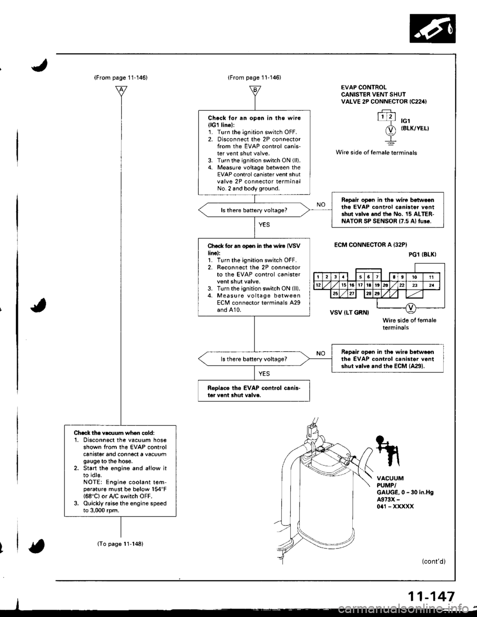
Chack tho vldlum wh.n cold:'1. Disconnscl the vacuum hoseshown from the EVAP controlcanrster ano connect a vacuumgauge to the hose.2. Start the engine and aliow itto idls.NOTE: Engine coolant tem-porat{rre must be below 154"F{68'C} or A/C switch OFF.3. Ouickly raise the engine speedto 3,000 rpm.
lFrom page 11-146)
Check lor an opon in lhe wir€(lG1 lin6l:1. Turn the ignition switch OFF.2. Disconnect the 2P connectorlrom the EVAP control canis-ter vent shut valve.3. Turn the ignition switch ON (ll).
4. Measure voltage between theEVAP control canister vent shutvalve 2P connector terminalNo. 2 and body ground.
Ropair open in the wir6 betweonthe EVAP control canistor v6ntshut valve end the No. 15 ALTER-NATOR SP SENSOR 17.5 Al tu!e.
Ch€ck tor rn op€n in iho wire IVSVline):1. Turn tho ignition switch OFF.2. Reconnect the 2P connectorto the EVAP control canistervent shut valve,3. Turn the ignition switch ON (ll).
4, Measure vo ltage betweenECN/l connector terminals A29and A10.
Repair open in the wire beiwa€nthe EVAP cont.ol cenister ventshut valve and the EcM {4291.ls there baftery vohage?
ReDlacs tho EVAP cont.ol canis"ter vent shut valve.
EVAP CONTROLCANISTER VENT SHUIVALVE 2P CONNECTOR IC224)
.FJ.\1121-T rcl
(D (BLK/YEL)
I
Wire side ot female terminals
ECM CONNECIOR A {32P}
VSV ILT GRNI
Wire side of femaletermtnars
VACUUMPUMP/GAUGE,0 - 30 in.H94973X -
0a1 - xxxxx
(cont'd )
11-147
PG1 (BLKI
rl
4lq-r'rri l12t5t6t?l8r@llzzlzslul
25212a2
__l
Page 353 of 1681
Emission Control System
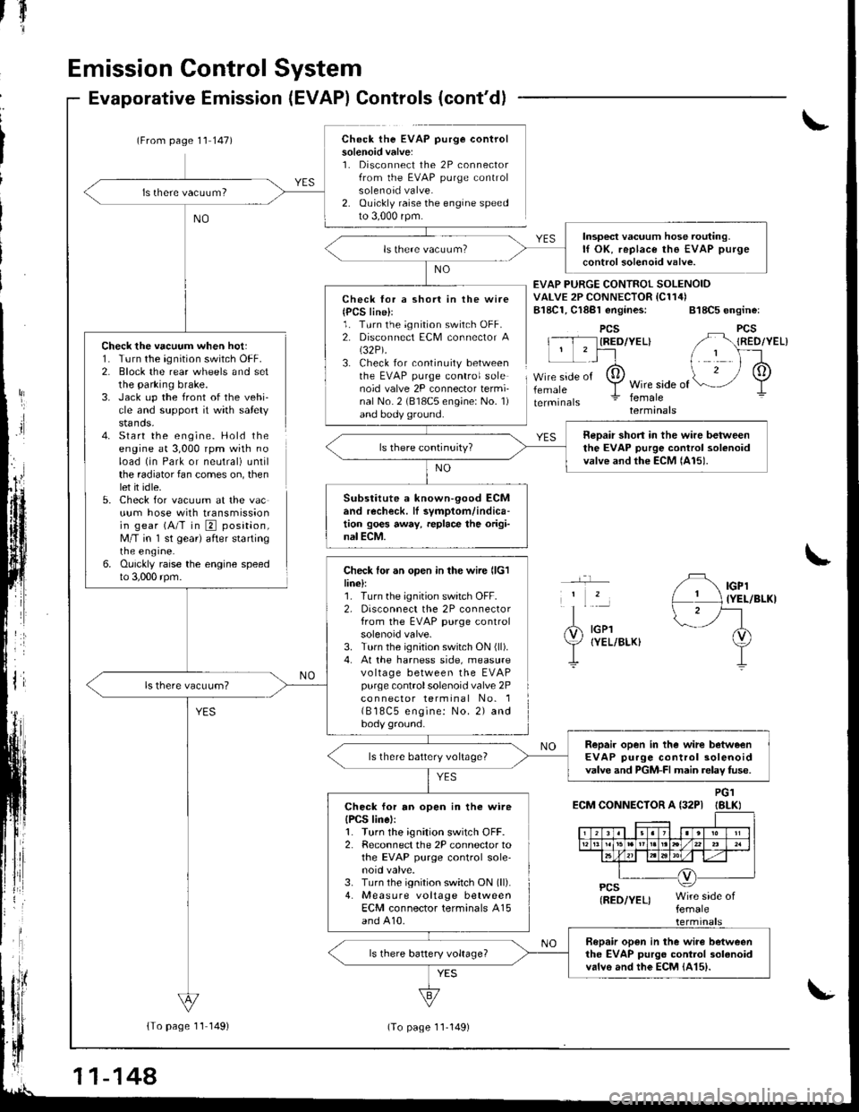
Check the vacuum when hot:1. Turn the ignition switch OFF.2. Block the rear wheels and setthe parking brake.3. Jack up the front of the vehi-cle and support it with safetystands.4- Start the engine. Hold theengine at 3,000 rpm with noload (in Park or neutral) untilthe radiator fan comes on, thenlet it idle.5. Check for vacuum at the vacuum hose with transmissionin gear (A/T in E position,M/T in 'l st gear) after startingrne engrne.6. Ouickly raise the engine speedto 3,000 rpm.
Evaporative Emission (EVAP) Controls (cont'd)
(From page 1'l 147)Check the EVAP purge controlsolenoid valve:1. Disconnect the 2P connectorfrom the EVAP purge controlsolenoid valve.2. Ouickly raise the engine speedto 3,000 rpm.
{To page 11 149)
tfl'I
Check lor a short in the wire{PCS line}l1. Turn the ignition switch OFF.2. Disconnect ECM connector A(32P).
3. Check for continuity betweenthe EVAP purge control solenoid valve 2P connector termi-nal No. 2 (818C5 engine: No. 1)and body ground.
Check for an open in the wire llclline):1. Turn the ignition switch OFF.2, Disconnect the 2P connectorfrom the EVAP purge controlsolenoid valve.3. Turn the ignition switch ON (ll).
4. At the harness side, measurevo ltage between the EVAPpurge controlsolenoid valve 2Pco n nector terminal No. 1( B 18C5 engine: No. 2) andbody ground.
EVAP PURGE CONTROI SOLENOIDVALVE 2P CONNECTOR IC114)B18C1, Cl8Bl engines: 818C5 engine:
PCSIRED/YEL}
femaleWire side offemaleterminals
YES
IGPl{YEL/BLKI
IGPlIYEL/BLKI
ECM CONNECTOR A {32PIPG1IBLKI
Insp€ct vacuum hose routing.lf OK, replace the EVAP purge
control solenoid valve.
neDair short in the wire betweenthe EVAP purge control solenoidvalve and the ECM lAl5).
Substitute a known-90od ECMand recheck. lI symptom/indica-tion goes away, replace the origi-nal ECM.
Repair open in the wirc betweenEVAP purge control solenoidvalve and PGM-FI main relav fuse.ls there battery voltage?
Check for an open in the wireIPCS linel:1. Turn the ignition switch OFF.2. Reconnect the 2P connector tothe EVAP purge control sole'noid valve.3. Turn the ignition switch ON (ll).
4. Measure voltage betweenECM connector terminals A15and A10.
Bopair open in the wiro betweenthe EVAP purgo control 3olanoidvalvo and the EcM {415).
11-144
(To page 11-149)
Page 355 of 1681
fIr
Emission Control System
Evaporative Emission Controls (cont'dl
t
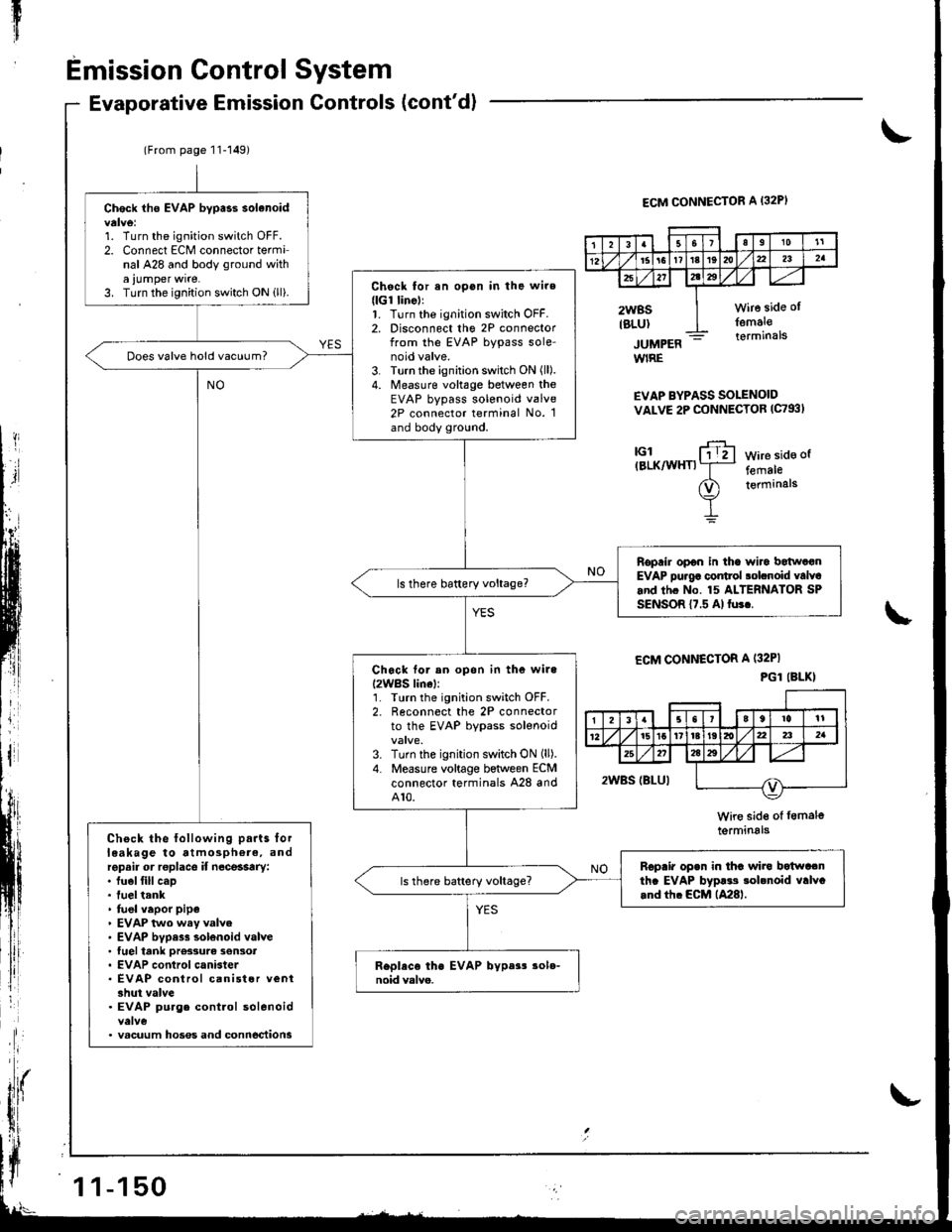
ECM CONNECTOR A I32PI
JUMPERWIRE
EVAP BYPASS SOLENOIDVALVE 2P CONNECTOB (C793I
tGl(BLK/WHTIWire side of
femaleterminals
\
ECM CONNECTOR A (32PI
PGl (BLKI
Wire side of lem6l6termrnals
(From page 11-149)
Check iho EVAP bypass solanoid
1. Turn the ignitioo switch OFF.2. Connect ECM connector terminal A28 and body ground witha ,umper wrre.3. Turn the ignition switch ON ill).Chock for an opon in the wire(lGr linell1. Turn the ignition switch OFF.2. Disconnect tho 2P connectorfrom the EVAP bypass sole-noid valve.3. Turn the ignition switch ON (ll).
4. Measure voltage between theEVAP bypass solenoid valve2P connector terminal No. 1and body ground.
Does valve hold vacuum?
Roprir opon in tha wiro batwatanEVAP pu.g6 control solcnoid valvcand thc No. 15 ALTERNATOR SPSENSOR {7.5 Al fu3..
Ch6ck tor an opon in the wile
I2WBS lin6l:'L Tlrrn the ignition switch OFF.2. Reconnect the 2P connectorto the EVAP bypass solenoid
3. Turn the ignition switch ON (ll).
4. Measure voltage between ECMconnector terminals A28 andA10.
Check the following parts lorleakage to atmosphere, andrepsir or roplace if n6ce$try:. fuel fill cap. fuel tank' fuel vapor pipe. EVAP two wsy valve. EVAP bvpess solenoid valve. tuel tank ore33urc son3ot. EVAP control canister. EVAP control canist6r veni3hut valve. EVAP purg. control solenoid
. vacuum hoses and conn6ctions
Rcpair opan in thc wira botwa.nth. EVAP byp!.s sobnoid valvc.nd tfi. ECM lA28l.
3Ia10't1
12l61611t8t9dta22a2a
x272tz3
2WBSIBLUI
wire side ol
femal€terminals
1 1-150
Page 372 of 1681
aintenance
Transmission Oil
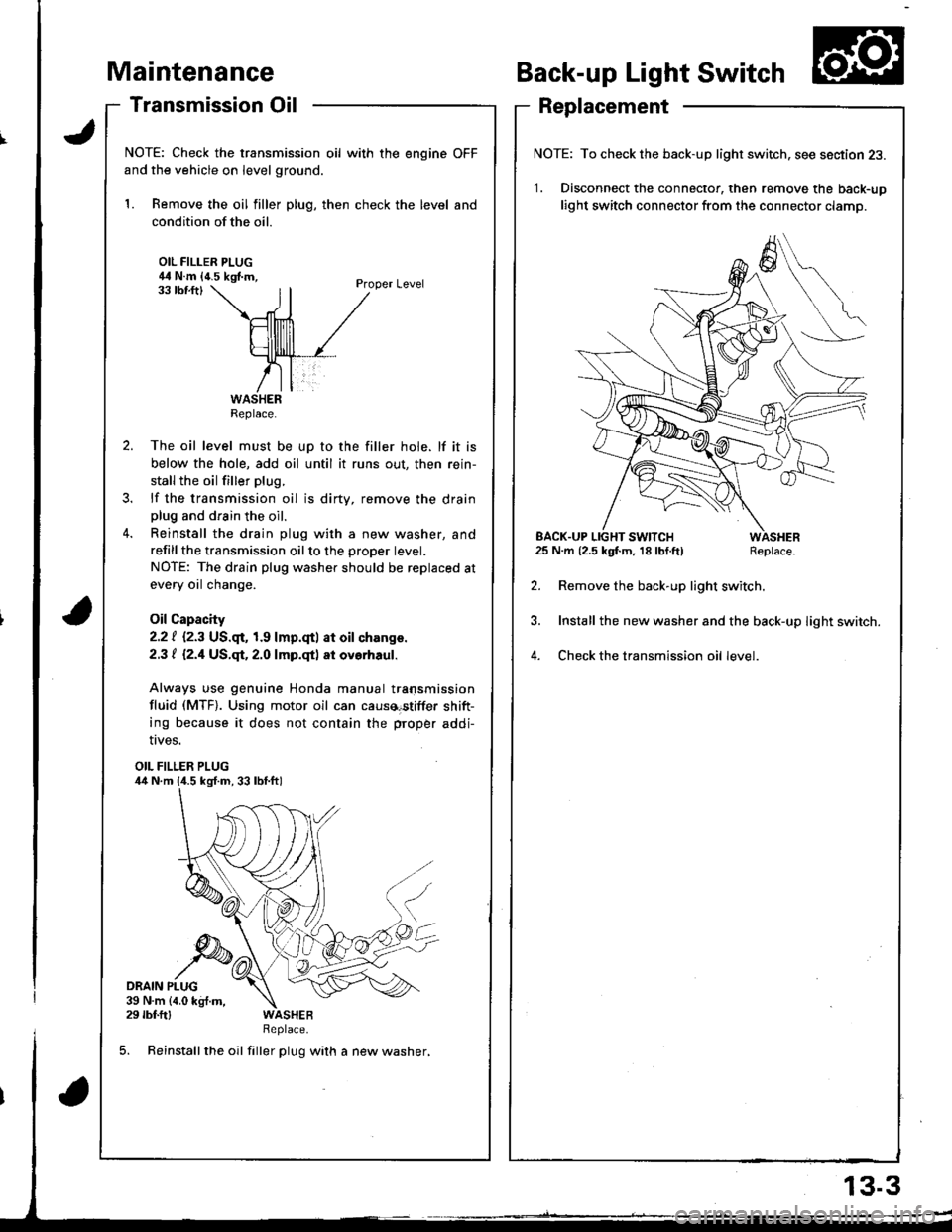
NOTE: Check the transmission oil with the engine OFF
and the vehicle on level ground.
1. Remove the oil filler plug, then check the level and
condition of the oil.
OIL FILLER PLUG44 N.m {4.5 kgf.m,Proper Level33 tbf.ftl
The oil level must be up to the filler hole. lf it is
below the hole, add oil until it runs out, then rein-
stall the oil filler plug.
lf the transmission oil is dirty, remove the drainplug and drain the oil.
Reinstall the drain plug with a new washer, and
refillthe transmission oilto the proper tevet.
NOTE: The drain plug washer should be replaced at
every oil change.
Oil Capacity
2.2 | i.2.3 US.qr,1.9 lmp.qtl at oil ch.nge.
2.3 t l2.1US.qt,2.O lmp.qtl at ovorhaul.
Always use genuine Honda manual transmission
fluid (MTF). Using motor oil can causa€tiffer shift-
ing because it does not contain the proper addi-
Back-up Light Switch
Replacement
NOTE: To check the back-up light switch. see section 23.
1. Disconnect the connector, then remove the back-up
light switch connector from the connector clamp.
l.m {2.5 kgf.m, 18lbf.ft) Replace.
Remove the back-up light switch.
Install the new washer and the back-up light switch.
Check the transmission oil level.
!ves.
OIL FILLER PLUG
DRAIN PLUG39 N.m {4.0 kg{.m,29 rbf.ftlReplace.
5. Reinstall the oil filler plug with a new washer,
Replace.
EACK.UP LIGHT SWITCH25 N.m {2.5 kgf.m, 18 lbf.ft)
13.3
Page 373 of 1681
Transmission Assembly
Removal
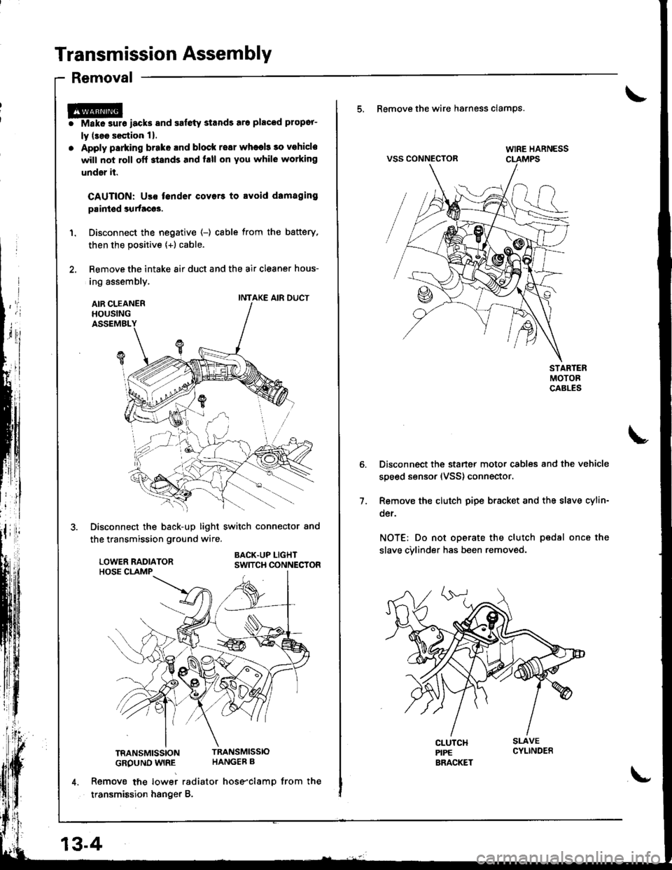
r@i Make surs iacks and safety stands sro placod propor-
ly (3ee s€ction 1).
. Apply parking brake and block resr whaeb 30 vohicle
will not roll off stands and hll on You whil6 working
under it.
CAUTION: Use fender covers to svoid damaging
paintod surtacos.
1. Disconnect the negative (-) cable from the battery,
then the positive {+) cable.
2. Remove the intake 8ir duct and the air cleaner hous-
ing assembly,
AIR CLEANERHOUSINGASSEMBL
Disconnect the back-up light switch connector and
the transmission ground wire.
BACK.UP LIGHTSWITCH CONNECTOR
TRANSMISSIONTRANSMISSIO
GROUND WIRE HANGEB B
4. Remove tne lowei radiator hose"clamp from the
transmission hsnger B.
INTAKE AIR DUCT
13-4
\-
5. Remove the wire hsrness clamps.
VSS CONNECTOR
Disconnect the starter motor cables and the vehicle
speed sensor (VSS) connector.
Remove the clutch pipe bracket and the slave cylin-
der.
NOT€: Do not operate the clutch pedsl once the
slave cvlinder has been removed.
7.
Page 416 of 1681
Transmission Assembly
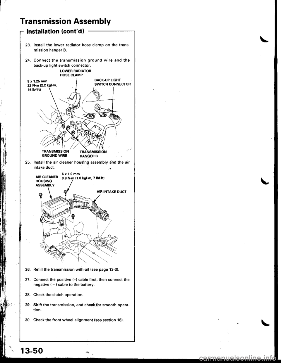
Installation (cont'd)
Install the lower radiator hose clamp on the trans-
mission hanger B.
Connect the transmission ground wire and the
back-up light switch connector.
LOWER RADIATORHOSE CLAMP
BACK.UP I-IGHTSWITCH CONNECTOR
24.
TRANSMISSIONGROUND WIRE
25. lnstall the air cleaner
intake duct.
AIR CIfANERHOUSINGASSEMBLY
HANGER B
hoqsing assembly and the air
6x1.0mm9.8 N.m 11.0 kgf.n,7 lbt'ft)
AI8 INTAKE DUCTY1
Reiill the transmission with€il (see page 13-3).
Connect the positive (+) cable first, then connect the
negative ( - ) cable to the battery.
Check the clutch operation.
Shift the transmission, and che6* {or smooth opera-
tion.
30. Check the front wheel alignment (se6 section 18).
21.
24.
13-50
Page 465 of 1681
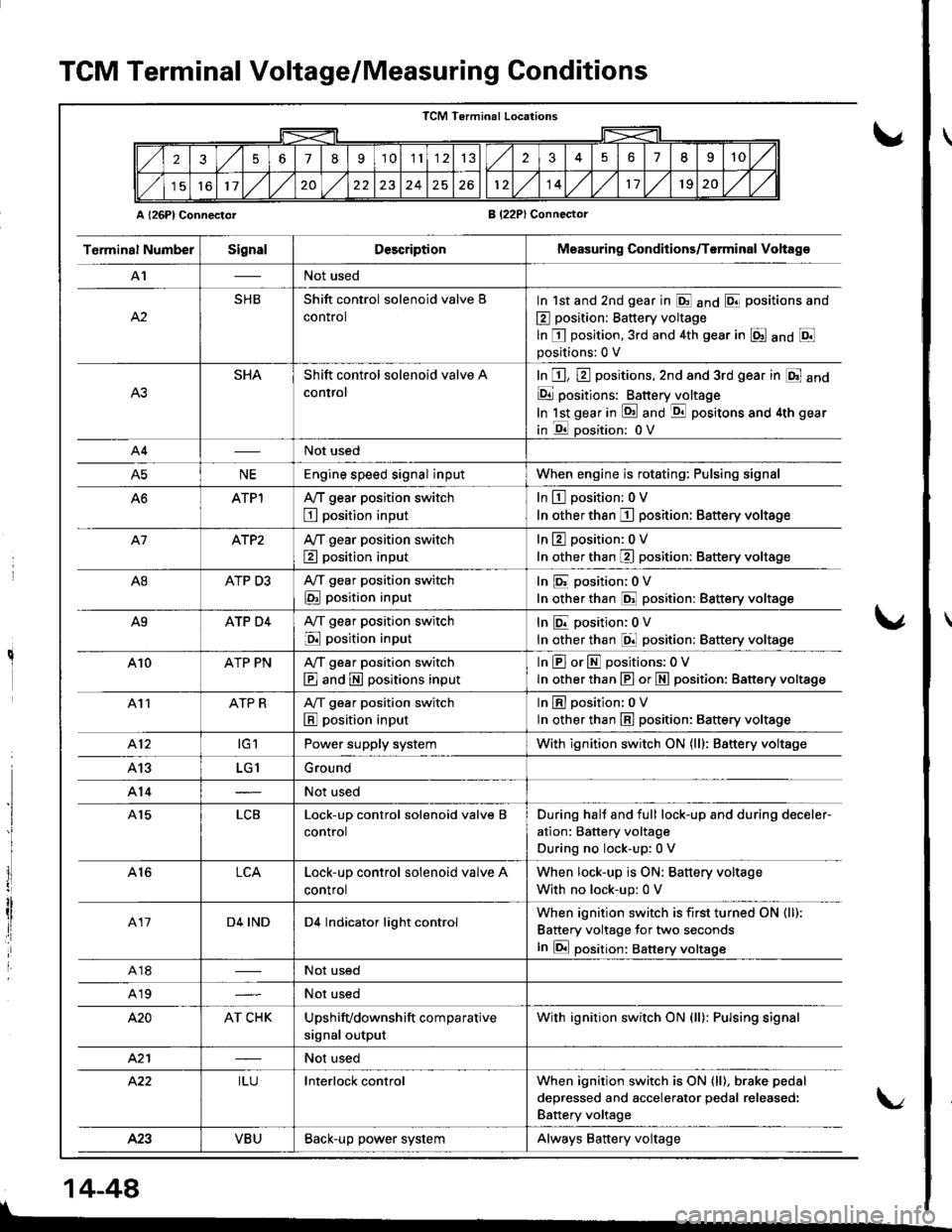
TCM Terminal Voltage/Measuring Conditions
A l26Pl ConnectorB (22PlConnector
TCM Terminal Locations
256789'1011132351II10
11,/l/2024261214,/l/1120,/1,/
T6rminal NumberSignalDescriptionMeasuring Conditions/T€rminal Voltag€
A'INot used
A2
SHBShift control solenoid valve B
control
In 1st and 2nd gear in E anO E positions and
E position: Battery voltage
ln E position,3rd and 4th gear in E anO Epositions:0 V
SHAShift control solenoid valve A
control
In E, E positions,2nd and 3rd gear in E and
E positions: Batteryjloltage
In lst gear in !d and -qtl positons and 4th gear
in E oosition: 0V
A4Not used
A5NEEngine speed signal inputWhen engine is rotating: Pulsing signal
ATPlA,/T gear position switch
E position input
In L!-l position: 0 V
In other than I position: Battery voltage
A7ATP2Ay'T gear position switch
E position input
In 13 position:0 V
In other than E position: Battery voltage
A8ATP D3A,/T gear position switch
E position input
In E position:0V
In other than @ position: Battery voltage
A9ATP D4A,/T gear position switch
E position input
InEposition;0V
In other than El position: Battery voltage
410ATP PNA,/T gear position switch
E and E positions input
InEorEpositions:OV
In other than E or N position: Battery vottage
411ATP RA/T gear position switch
E position input
lnEposition: oV
ln other than E position: 8attery voltage
412tGlPower supply systemWith ignition switch ON (lll: Battery voltage
413LG1Ground
A14Not used
A15LCBLock-up control solenoid valve B
control
During hall and full lock-up and during deceler-
ation: Battery voltage
During no lock-up:0 V
A16LCALock-up control solenoid valve A
control
When lock-up is ON; Battery voltage
With no lock-up: 0 V
417D4 INDD4 Indicator light controlWhen ignition switch is first turned ON (ll):
Battery voltage for two seconds
In E position: Battery voltsge
A18Not used
A19Not used
420AT CHKUpshifvdownshift comparative
signal output
With ignition switch ON (ll): Pulsing signal
421Not used
422ILUInterlock controlWhen ignition switch is ON (ll), brake pedal
deoressed and accelerator oedal released:
Battery voltage
423VBUBack-up power systemAlways Battery voltage
I
lI
I
14-44
\/