ground HONDA INTEGRA 1998 4.G Repair Manual
[x] Cancel search | Manufacturer: HONDA, Model Year: 1998, Model line: INTEGRA, Model: HONDA INTEGRA 1998 4.GPages: 1681, PDF Size: 54.22 MB
Page 466 of 1681
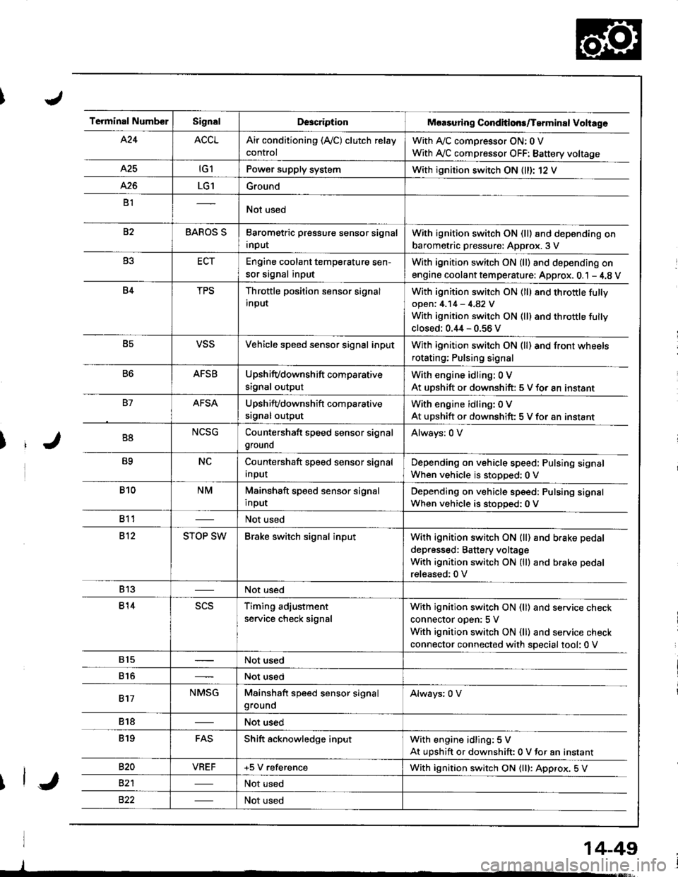
Terminal NumberSignalDescriptionMaasuring Conditlons/Tarminal Voliage
424ACCLAir conditioning (Ay'C) clutch relay
control
With A,/C comDressor ON: 0 V
With Ay'C compressor OFF: Battery voltage
A25tG1Power supply systemWith ignition switch ON (ll)r 12 V
426LG1Ground
B1Not used
82BAROS SBarometric pressure sensor signal
input
With ignition switch ON (ll) and depending on
barometric pressure: Approx. 3 V
B3ECTEngine coolant temperature sen-
sor signal input
With ignition switch ON (ll) and depending on
engine coolant tem perature: Approx. 0.1 - 4.8 V
B4TPSThrottle position sensor signal
input
With ignition switch ON (ll) 8nd throttle fully
open: 4.14 - 4.82 V
With ignition switch ON (ll) and throttle fully
closed: 0.44 - 0.56 V
B5VSSVehicle speed sensor signal inputWith ignition switch ON (ll) and front wheels
rotating; Pulsing signal
B6AFSBUpshifvdownshift comparative
signal output
With engine idling: 0 V
At uDshift or downshift: 5 V for an instant
B7AFSAUpshifvdownshift com parative
srgnal output
With engine idling: 0 V
At upshift or downshift: 5 V for an instant
B8NCSGCountershaft speed sensor signal
ground
Always: 0 V
B9NCCountershaft speed sensor signal
Input
Depending on vehicle speed: Pulsing signal
When vehicle is stopped:0 V
B10NMMainshaft speed sensor signal
input
Depending on vehicle speed: Pulsing signal
When vehicle is stoDoed: 0 V
811Not used
812STOP SWBrake switch signal inputWith ignition switch ON {ll) and b.ake pedal
depressed: Battery voltage
With ignition switch ON (lll and brake pedal
released:0 V
813Not used
814scsTiming adjustment
service check signal
With ignition switch ON (ll) and service check
connector oDen:5 V
With ignition switch ON (ll) and service check
connector connected with special tool: 0 V
815Not used
816Not used
817NMSGMainshaft speed sensor signalgroundAlways: 0 V
818Not used
819FASShift acknowledge inputWith engine idling: 5 V
At upshift or downshift: 0 V for an instant
820VBEF+5 V referenceWith ignition switch ON {lll: Approx. 5 V
82'lNot used
Not used
14-49
Page 476 of 1681
\/
J
14-59
From page 14-58
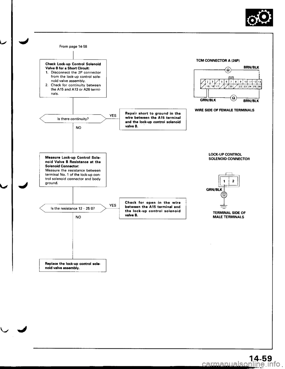
Chock Lock-up Contlol SolonoidValv6 8 tor ! Short Circuit:1. Disconnect the 2P connectorIrom the lock-rrp control sole-noid vaive assembly.2. Check for continuity betweenthe A15 and A13 or 426 termi-nals.
Rspsir rhort to ground in thowirg bgtwoen tho A15 torminaland the lock-uD control 3ol6noidvalva B.
Maasuro Lock-up Control Sola-noid V.lvo B Rosist.nc6 at theSolonoid Connactor:Measure the resistance betweenterminal No. 'l of the lock-uo con-trol solenoid connector and bodygrouno.
Chack tor open in tho wir6botwe.n th€ A15 to.minal andtha lock-up conlrol aolenoidv.lv. B.
ls the resistance 12 - 25 O?
Roplace lhe lock-up codrol role-noid vrlvo a$embly.
TCM CONNECTOR A I26PI
WIRE SIDE OF fEMALE TERMINALS
LOCK.UP CONTBOLsotf Noto coNNEcToB
r '
ll ' | , llIr_e_rtjl
cnrurefiT-/Or
-L--=
TERMINAI SIDE OFMALE TERMINALS
Page 484 of 1681
From pege 14-66
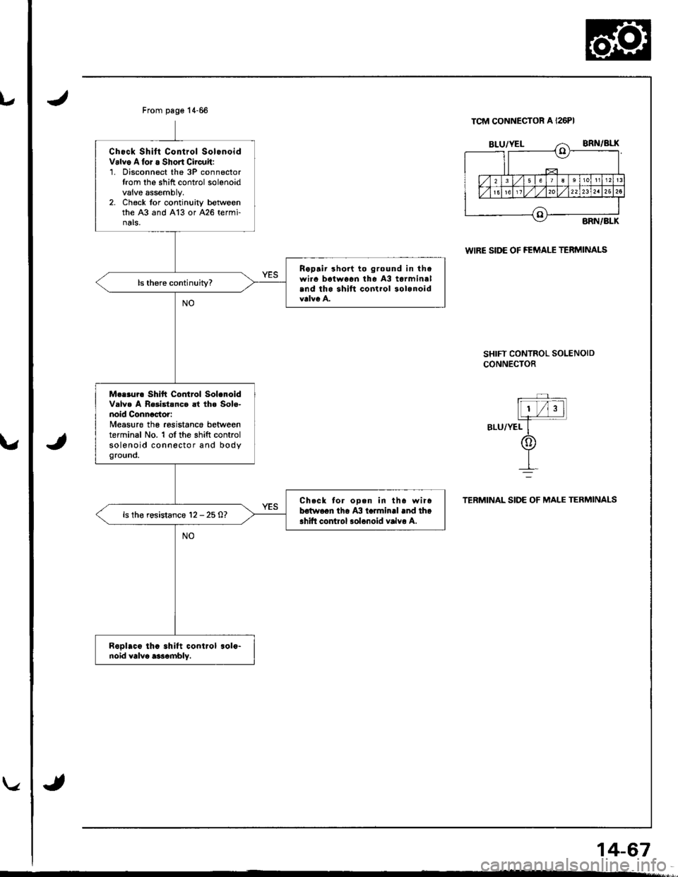
Chock Shitt Control SolonoidValvo Alor a Short Circuit:1. Disconnect the 3P connectortrom lhe shift control solenoidvalve assembly,2. Check lor continuity betwoenthe A3 and A13 or A26 termi-nals,
Rapair sho.t to ground in thswi.c batwocn tha A3 torminalind th6 shift control 3olanoid
Mearur. Shitt Control Sol.noidValv. A Re3istsnce at th. Sol€-noid Connactor:Measur€ the rosistance betweenterminal No. 1 of the shift controlsolenoid connector and bodyoround.
Chcck tor ooen in th6 wir6betwocn the A3 tclminll .nd tho.hift control 3ol6noid vrlvo A.ls the rosistsnce 12 - 25 0?
Repl.c6 th. .hltt control .016-noid valvo aarcmbly.
TCM CONNECTOR A I26PI
WIRE SIDE OF FEMALE TERMINALS
SHIFT CONTROL SOLENOID
CONNECTOR
Ll /i3 tL
ar-urvelf-
@
IL--
TERMINAL SIDE OF MALE TERMINALS
14-67
Page 486 of 1681
u
From pag€ 14-68
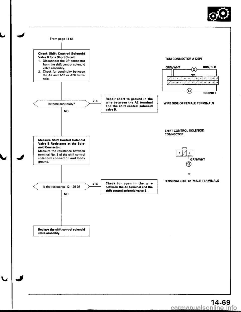
Chock Shitt Control Sol.noidV.lv! B tor r Short Circuit:1. Disconngct th6 3P connoctortrom the shift control solenoidvalve sssombly.2. Check for continuitv betwo€nth€ A2 and 413 or 426 tormi-nals.
Rapalr lhort to ground in ihowirc batwoan lhc A2 tarminaland th6 ihlft control 30lcnoidvalva B.
M...ur. Shift Control Sol.noidValv. B R.rid.[c. rt tha Sol.-noid Connactor:Measure the resistanc6 betweenterminal No, 3 of th€ shitt controlsolenoid connector and bodyground,
Ch.ck for open in lh. wi..batwaon th6 42 torminrl rnd thoahitt control lolanoid valva B.
ls the resistance l2 - 25 0?
TCM CONNECTON A I26PI
WIRE SIDE OF FEMALE TERMINALS
SHIFT CONTROL SOLENOIDCONN€CTOR
GRN/WHT
TERMINAL SIDE OF MALE TERMINALS
14-69
Page 487 of 1681
Electrical Troubleshootin g
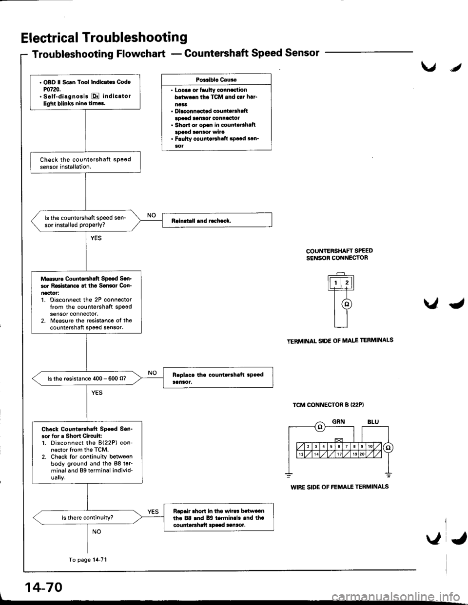
Troubleshooting Flowchart - Countershaft Speed Sensor
Posalbla Cruae
. Loora or faulty connactionb.tw.$ tho TCM and 61 h!1.
na33. Dbconnactad couniaBhaftlocad lantot oonnac{ot. Shorl or opan in counta6hatttDaad $naor wha. F.ultv coufiaEh.ft apaad acn-aol
COUNTERSHAFT SPEEDSENSOR CONNECTOR
\IJ
U\lO
.-_
lfr-trtlL+l-r-T-
t@tl
L__l
TENMINAL SIDE OF MAIE
TCM CONNECTON B (22PI
TERMINALS
L
14-70
WIBE SIDE OF FEMALE TERMINALS
. OBD ll Scrn Tool Indlcat ! Cod.m720.. Self-diagnosis E indicatollighl blinks nine tim6.
ls the countershaft speed sen-sor installed properly?
Moas{ra Cour 6Ghaft Sp€od Sen-60r R6Btanca gt iha SaGol Con-n€c'tor:1. Disconnect the 2P connectortrom the countershafl spgodsensor connectof.2. Measure the resistance ol thecountershaft speed sensor.
ls the rosistance 400 - 600 O?
Check Countorrhcft Spe.d Son-3ol for r Shon Circuit:1. Disconnect the 8{22P) con-nector lrom the TCM.2. Ch€ck lor continuity betweenbody ground and the 88 t€r-minal and Bg terminal individ-ually.
Rapair rhon In th6 wiro! hwaantho E8 rnd Bg te.min.l. .nd th.countaFhaft !D..d aanaol.
To page'14-71
\,a,
Page 492 of 1681
v
u
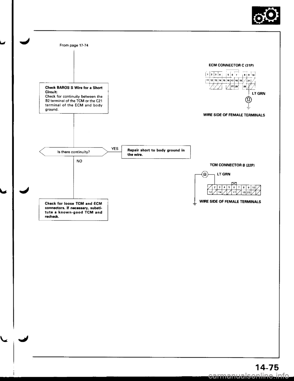
From page 17-74
Check BAROS S Wiro tor a ShortCircuh:Check for continuity between the82 terminal ofthe TCM or the C21terminal ot the ECM and bodyground.
Ch.ck {or loose TCM and ECMconnoctots. lf n€cessary, sub3ti-tut6 a known-good TCM androchock.
WIRE SIDE OF FEMALE TERMINALS
TCM CONNECTOR B {22PI
WIRE SIDE OF FEMALE TERMINALS
14-75
Page 494 of 1681
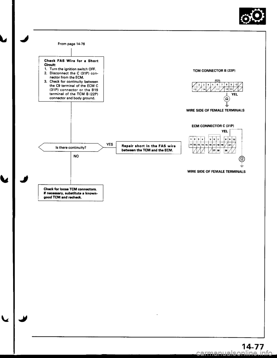
From pag€ 14-76
Ch.ck FAS Wir! for I ShoitClrc!hr1. Turn th6 ignition swilch OFF.2. Disconnect the C (31P) con-n€ctor from tho ECM.3. Chock for continuiv b€tweonth€ c9 torminal of th6 EcM c(3'lP) conn6ctor or the 819torminal of th€ fcM B l22Plconnoctor and body ground,
B.pllr rhort in th. FAS wirob.tw..n th. TCM .nd th. ECM.
Chack tor looaa TCM connactora.lf nacaaary, aubatltuta I known.good TCM .nd rach..k.
TCM CONNECTOR B {22P}
WIRE SIDE OF FEMALE TERMINALS
ECM CONNECTOR C {31PI
WIRE SIDE OF FEMALE TERMINALS
14-77
Page 495 of 1681
Electrical Troubleshootin g
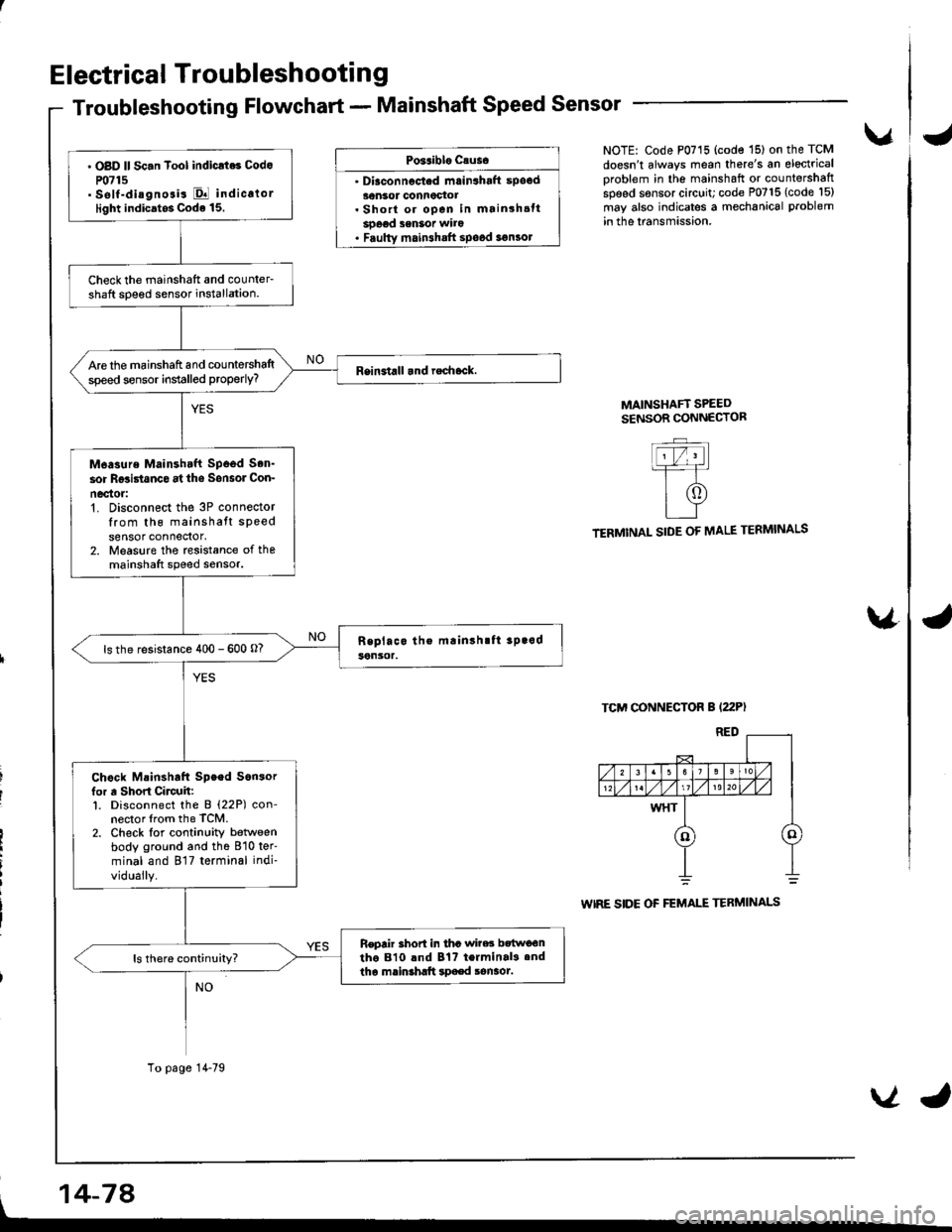
Troubleshooting Flowchart - Mainshaft Speed Sensor
Po3aiblo causo
' Diaconnocted mrin3haft spocd30nsor connoctot. Short or open in mainshsttsoeod senSot wito. Faulty main3halt spood 3€n3ol
vNOTE: Code P0715 (code '15) on the TCM
doesn't always mean there's an electrical
oroblem in the mainshaft or countershaftspeed sensor circuit; code P0715 (code l5)
may also indicates a mechanical problem
in the lransmission.
MAINSHAFT SPEEDSENSOR CONNECTOR
TERMINAL SIDE OF MALE TERMINALS
TCM CONNECTOR B (22P)
WIRE SIDE OF FEMALE TERMINALS
\4
' OBD ll Sc.n Tool indicrt6 Codo
P0715' self-diagnosis El indicalorlight indicatos Code 15.
Check the mainshatt and counler-shaft soeed sensor installation.
Are the mainshaft and countershaltspeed sensor installed properly?
M6asure Mainshtft Spood Son'
sor Rgsi5tanco at ths Sonsol Con-
nec'tor:'t. Disconnect the 3P connectorIrom th6 mainshatt speedsensor connedor,2. Measure the rcsistance of themainshaft speed sensor.
ls the resistance 400 - 600 o?
Chock Mainshaft Speed Son3orfor a Short Circuh:l. Disconnect the B (22P) con-nector lrom the TCM.2. Check lor continuity betlveenbody ground and the 810 ter'
minal and 817 terminal indi-
vidually.
Repair 3hort in tha wi?es bttwo€ntho 810 lnd Bt? terminal3.ndtha mainshltt spaed sonaot.
To page 14-79
, 14-74
VJ
Page 499 of 1681
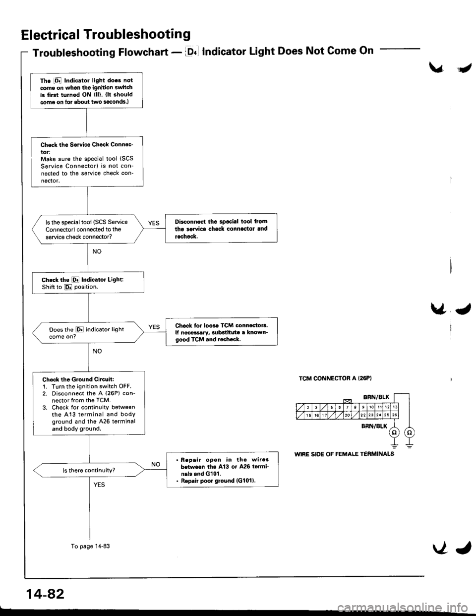
Electrical Troubleshooting
Troubleshooting Flowchart - lDnl IndicatorLight Does Not Come On
\/J
Check the Sowice Chock Connec-lol:Make sure the special tool {SCSSorvice Connector) is not con-nected to the service check con-
nector.
\/J
TCM CONNECTOR A I26PI
The iDal Indic.tor light does not
coma on whgn the ignhion switchis tirst tulnod ON {ll). (lt should
come on tor about two s€conds.)
Disconnect the 3pocisl tool from
tho sgrvice chock connlc'tor and
rachock.
ls the specialtool (SCS Service
Connedor) connected to the
service check connector?
Ch.ck tho [O! Indicator Light:Shiftto E position.
Chock tor loos. TCM conn.ctoi3.lf nece3s!ry, subttitute a known-good TCM and r.ch.ck,
Does the E indicator lightcome on?
Ch.ck the Ground Circuit:1. Turn the ignition switch OFF.2. Disconnect the A 126P) con-nector from the TCM.
3. Check lor continuity botweenthe A13 terminal and bodyground and tho 426 terminaland body ground.
Reprir opan in the wir.3betwoon th6 A13 or A26 t..mi-nil. and G101.Repair poor ground (G101).
To page 14-83VJ
14-a2
t-
Page 501 of 1681
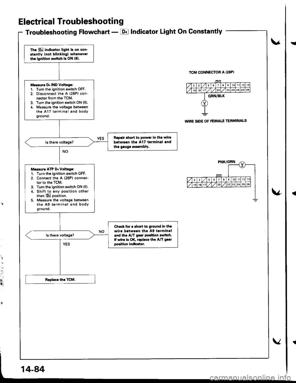
Electrical Troubleshooting
Troubleshooting Flowchart - EIndicator Light On Gonstantly
v
ICM CONNECTOR A I26PI
\4
I
i
rlIti
Th. E indicltor ligM i! on cor.
.t.ntly Inoi blinllng) wh.n.Y.l
th. lgrhior lwftch l. ON {ll).
M...ur. D. INO Vohtg.:1. Turn tho ignition switch OFF.
2. Disconnect th€ A (26P) con-noctor from the TCM.3. Turn the ignition switch ON (ll).
4. Measure thg voltag€ bstwegnthe A17 t6rminal and bodyground.
Rapalr ahort to powar In tha wiru
b.tw..n th. A17 l.rmin.l lnd
tha gaug. .cr.mbly.
M.a3ur. ATP D. voh.g.:1. Turn the ignition switch OFF.2. Conn€ct th€ A (26P) conn€c-tor to the TCM.3. Turn th€ ignition switch ON (ll).
4, Shift to any position otherthan E position.
5. Moasure the vohag€ b€tweenthe A9 tormin.l and bodyground.
Ch.ck tor r rhort to ground in thawir. b!tw..n th. Ag tarmin.l.nd th. A/T g..r potfion lwltch.f wi.e b OK r.pllca th. A/T g.|rpolition Indacrtor.
WIRE SIDE OF FEMAI.I TERMINALS
!
{