main relay HONDA INTEGRA 1998 4.G Service Manual
[x] Cancel search | Manufacturer: HONDA, Model Year: 1998, Model line: INTEGRA, Model: HONDA INTEGRA 1998 4.GPages: 1681, PDF Size: 54.22 MB
Page 1121 of 1681
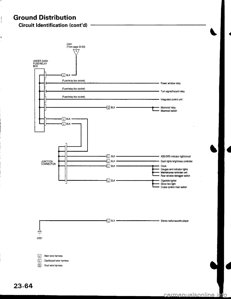
Ground Distribution
JUNCIIONCONNECTOR
U : Main wrre larness
E : oashboardwire haness
E , B*tr,it" h",n"..
Circuit ldentification (cont'dl
G40l(From page 23-63)
UNDEN.DASIFUSEi RELAYBOX
Turn sbnal/he2ad relay
hlegraled conlrol unil
BLh-Moonlmlleray- MooNool switch
BLK
BLK
8LK
ABS/SRS indicalor lighvci.dril
oash lighls brighhess clitroller
ClockGauges and indicalor lighlsMaiol€nan6 Gmind€a milR6ar window d6logger switch
A-^..'.''..'..- Cqal€nergrnet
l- Glove box lighlr- Ouise conlrol nan sw|ldr
Steleo mdio/cassello playel
G551
23-64
Page 1128 of 1681
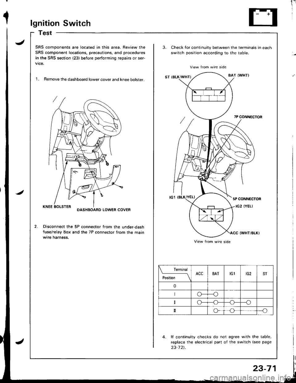
1lgnition Switch
Test
J
J
SRS components are located in this area. Review the
SRS component locations. precautions, and procedures
in the SRS section (23) before performing repairs or ser-
vtce.
'I . Remove the dashboard lower cover and knee bolster.
3.Check for continuity between the terminals in each
switch position according to the table.
View from wire side
ST IBLK/WHT}BAT (WI{TI
7P CONNECTOR
5P CONNECTOR
IG2 (YELIDASHBOARD LOWER COVER
Disconnect the 5P connector from the under-dash
fuse/relay box and the 7P connector from the mainwrre harness.IWHT/BI-K}
4. ll continuity checks do not agree with the table,
replace the electrical part of the switch {see page
23-7 2).
View from wire side
Terminal
PositionACCBATtGlrG2ST
o
o---o
o--_o
0o---o
23-71
Page 1130 of 1681
;
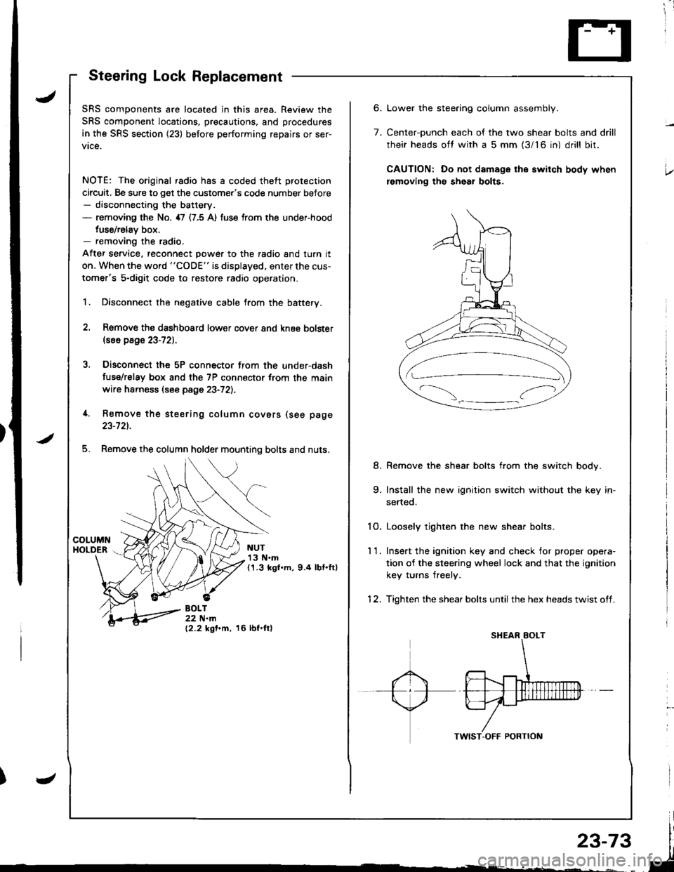
Steering Lock Replacement
SRS components are located in this area. Review the
SRS component locations, precautions, and procedures
in the SRS section (23) before performing repairs or ser-
vice.
NOTE: The original radio has a coded theft protection
circuit. Be sure to get the customer's code number before- disconnecting the battery.- removing the No. 47 (7.5 A) fuse trom the under-hood
fuse/relav box.- removing the radio.
After service, reconnect power to the radio and turn it
on. When the word "CODE" is displayed. enter the cus-
tomer's 5-digit code to restore radio operation.
1. Disconnect the negative cable from the battery.
2. Remove ths dsshboard lower cover and knee bolster(s6o p8ge 23-72).
3, Disconnect the 5P connector from the under-dash
fuse/relay box and the 7P connsctor from th€ main
wire harness (see page 23-72l.,
4. Remove the steering column covars (see page
23-721.
5. Remove the column holder mounting bolts and nuts.
NUT13 N.m(1.3 kgl.m, 9.4 lbt.ftl
BOLT22 N.m(2.2 kgf.m, 16 lbf.ftl
6.
7.
Lower the stee.ing column assembly.
Center-ounch each of the two shear bolts and drill
their heads oft with a 5 mm {3/16 in) drill bit.
CAUTION: Do not damage the switch body when
lemoving th€ sheal bolts.
Remove the shear bolts from the switch body.
Install the new ignition switch without the key in-
serted.
1O. Loosely tighten the new shear bolts.
11. Ins€rt the ignition key and check for proper opera-
tion of the sleering wheel lock and that the ignition
key turns freely.
12. Tighten the shear bolts until the hex heads twist off.
8.
Page 1180 of 1681
UNDER.DASHFUSE/RELAY 8OX
No.l5 (7.54)
No 2s (7 5A)
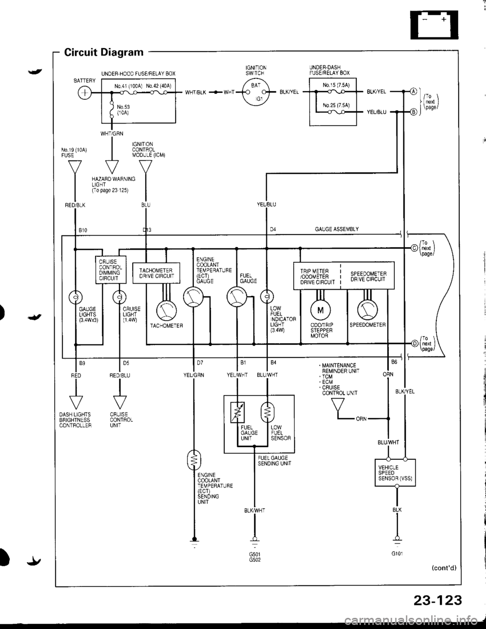
Gircuit Diagram
WHTiGRN
| $il,�4,
V
MODULE(ICM)
ru{no unrno I(To pase 23 12s)
|BtU
No.rs (10A)FUSE
V
I
GAUGE ASSEMBLY
YEUBLU
t,,
| ,,J,,
1l
|;;il'-II SPEED II SENSoBIVSS) |-t-
. MAINTENANCEREMINDER UNIT' TCM' ECM' CRUISECONTROT UNlT
f7
I-oRN
BLKMHT
I
G501
I'YEUGRN YE
ln
tl
P**,,,'
ffirxl-"
louRED/BLU
.J'-
CRUISECONTROLUNIT
BLK
I
G10l
23-123
-/
UNDEF HOOD FUSE/RELAY BOX
Page 1195 of 1681
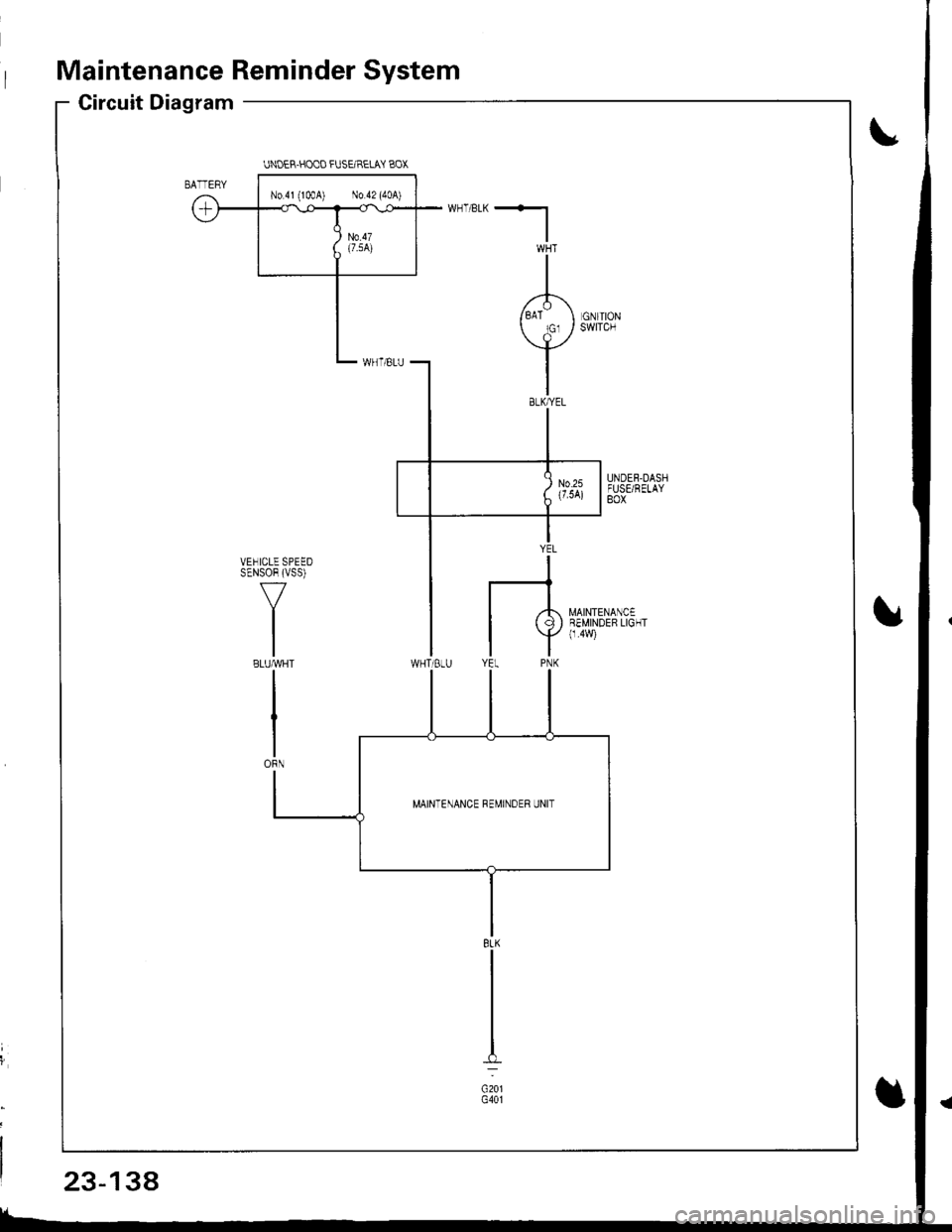
Maintenance Reminder System
Circuit Diagram
UNOER.HOOO FUSEIRELAY BOX
N0.41 (lmA) No 42 (40A)
MAINTENANCE REMINDER UNIT
8LK
c201G401
23-138
Page 1196 of 1681
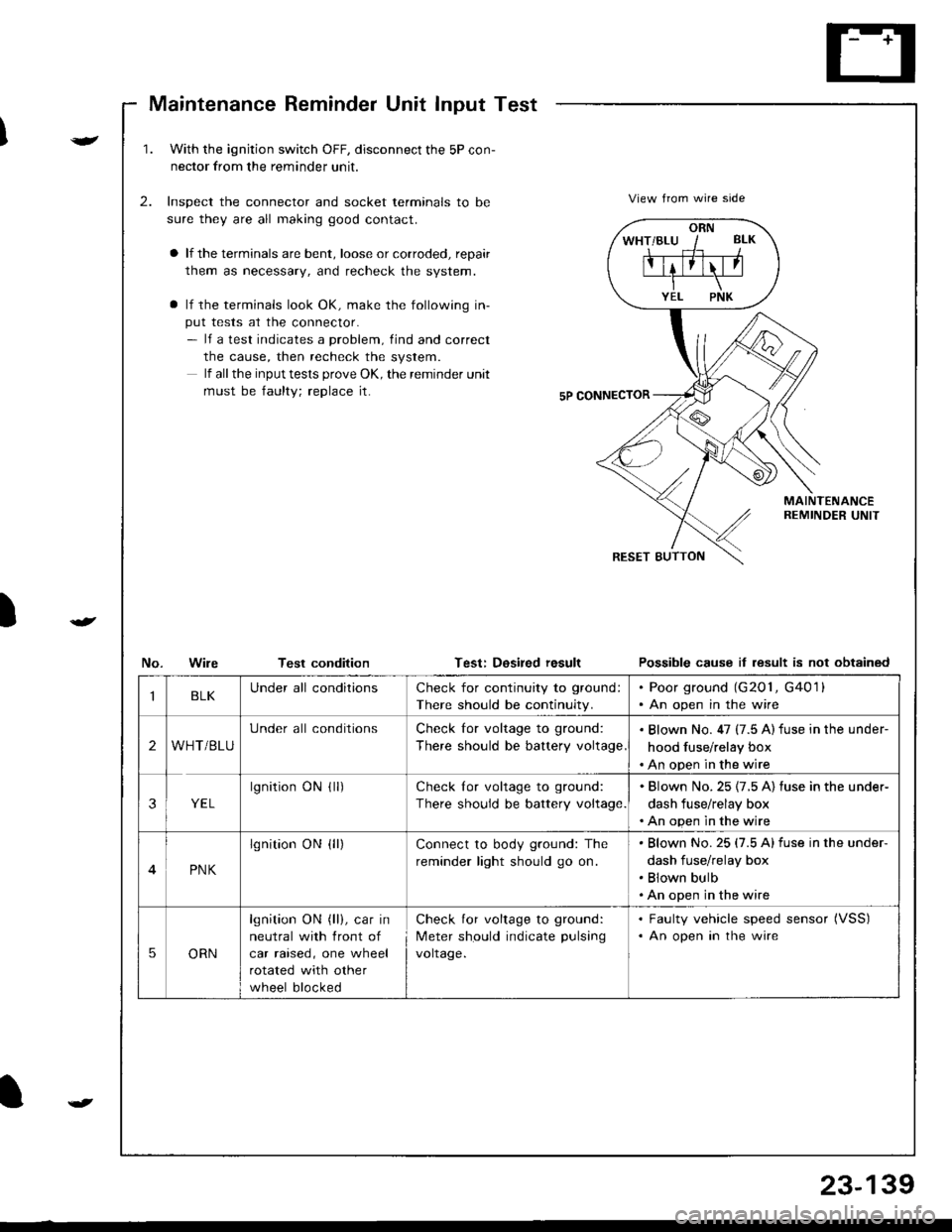
Maintenance Reminder Unit Input Test
)
v
t
1.With the ignjtion switch OFF, disconnect the 5P con-
nector from the reminder unit.
Inspect the connector and socket terminals to be
sure they are all making good contact.
a lf the terminals are bent, loose or corroded, repair
them as necessary, and recheck the system.
a lf the terminals look OK, make the following in-
put tests at the connector.- lf a test indicates a problem, find and correct
the cause, then recheck the system.
lf all the input tests prove OK, the remind€r unit
must be faulty; replace it.
2.View from wire side
MAINTENANCEREMINDER UNIT
No.WileTest conditionTest: Dosired resultPossible cause it lesult is not obtained
ORN
IBLKUnder all conditionsCheck for continuity to ground:
There should be continuity.
. Poor ground (G201, G4011. An open in the wire
2WHT/BLU
Under all conditionsCheck for voltage to ground:
There should be battery voltage
. Blown No. 47 (7.5 A) fuse in the under-
hood fuse/relay box. An open in the wire
3YEL
lgnitionONflr)Check lor voltage to ground:
There should be battery voltage.
. Blown No.25 {7.5 A) fuse in the under-
dash fuse/relay box. An open in the wire
4PNK
lgnition ON {ll)Connect to body ground: The
reminder light should go on.
Blown No.25 (7.5 Alfuse in the under-
dash fuse/relay box
Blown bulb
An open in the wire
5ORN
lgnition ON (ll), car in
neutral with front of
car raised, one wheel
rotated with other
wheel blocked
Check for voltage to ground:
Meter should indicate pulsang
voltage.
. Faulty vehicle speed sensor (VSS)
. An open in the wire
t
23-139
Page 1235 of 1681
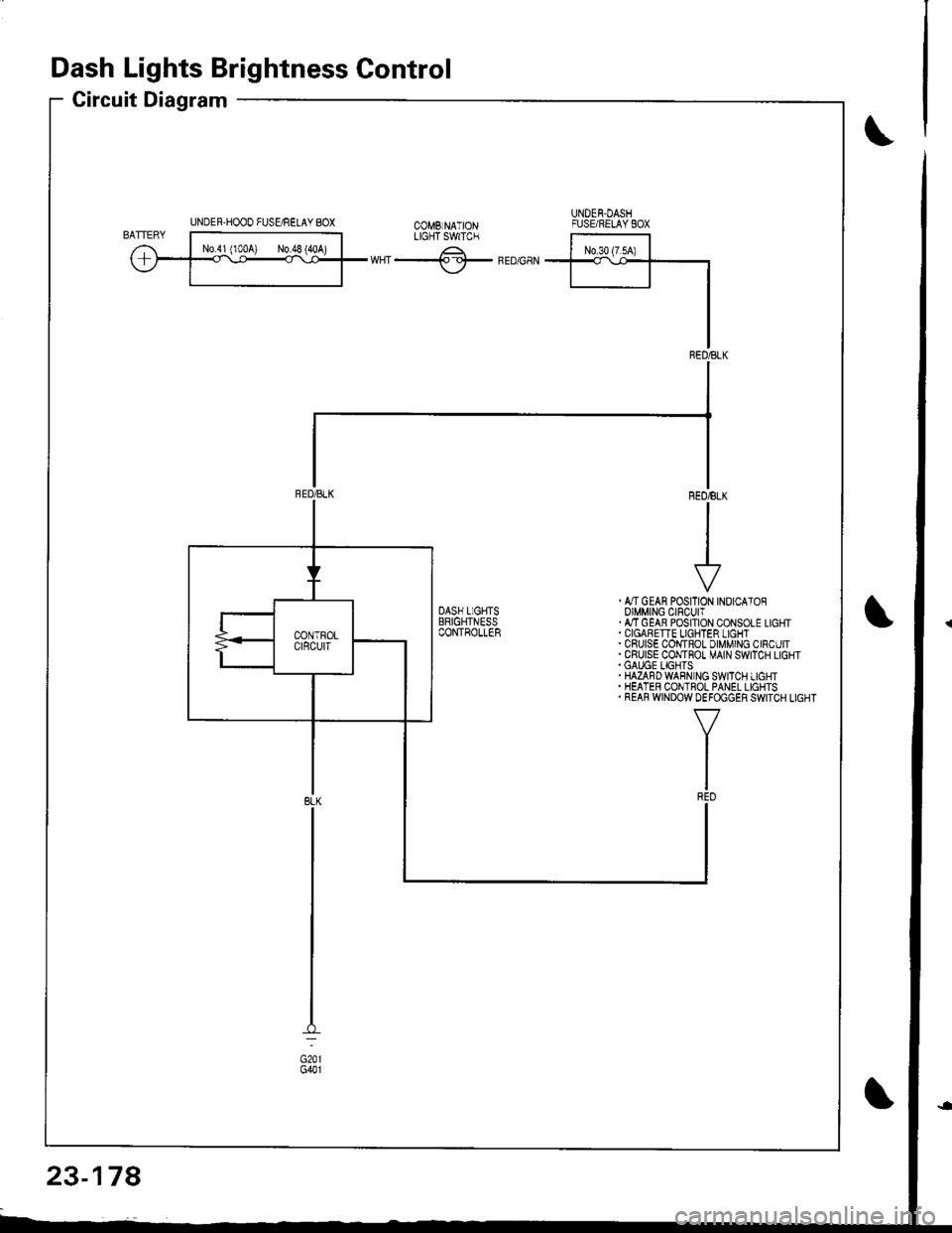
Dash Lights Brightness Control
Circuit Diagram
UNDER-HOOO FUSgRELAY 8OXUNDEN.DASHFUSE/RELAYEOXtX"f -.------^-;^*;;ilLrcrTswrc.
ffiwHT-lf-FEDGaN
, &TGEAN POSITION INOICATOROIMMING CIFCUIT.ATTGEAB POSITION CONSOLE LIGHT
. CRUISE COI,{TROL DIMMING CIRCUIT.CRUISE CONTHOT MAIN SWITCH LIGHT.GAUGE LIGHTS.HAZAFDWABN NG SWITCH LIGHT. HEATER CONTROL PANEL LIGHTS. REAR WINDOW DEFOGGER SWITCH LIGHT
23-178
Page 1263 of 1681
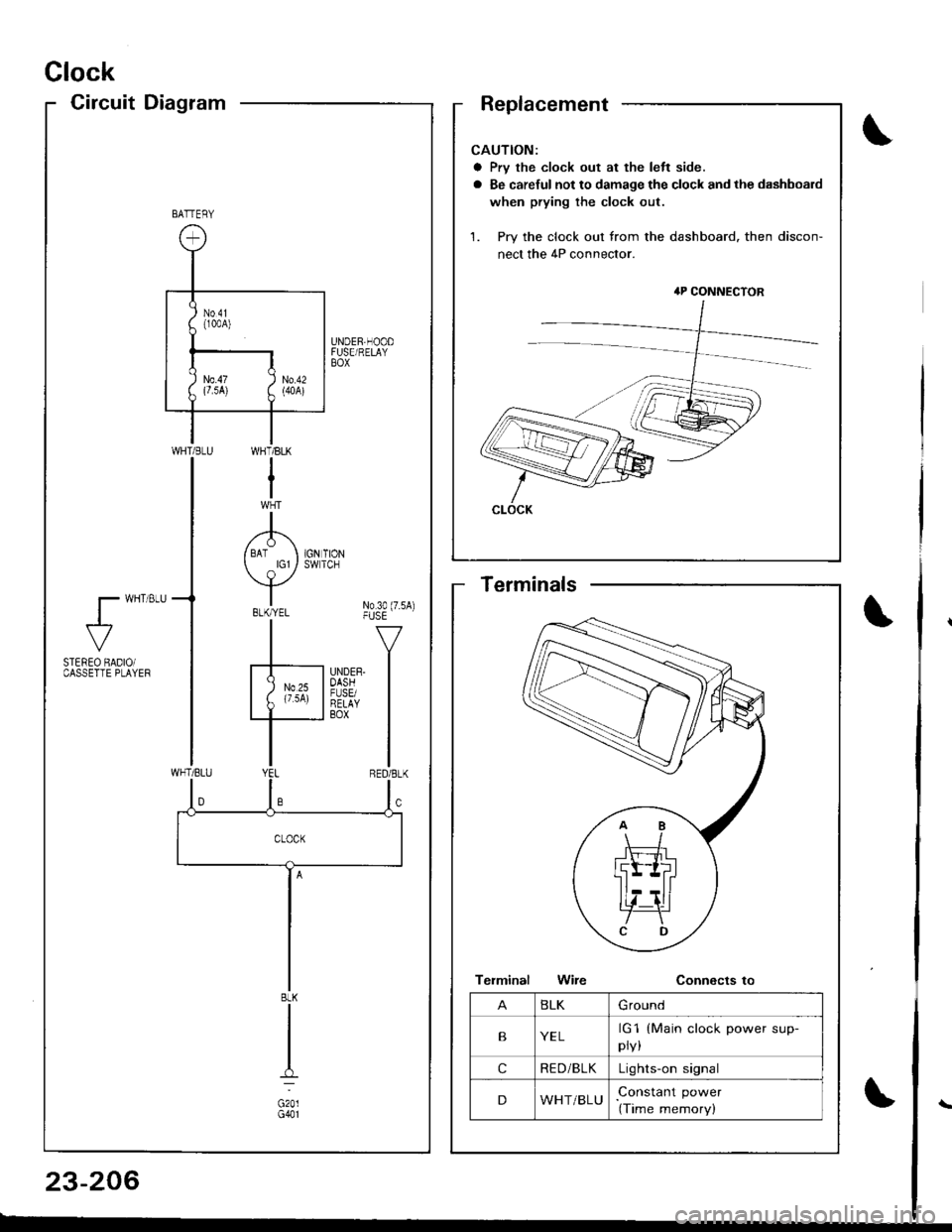
Clock
CircuitDiagram
CAUTION:
a Prv the clock out at the left side.
a Be careful not to damage the clock and the dashboard
when prying the clock out.
1. Pry the clock out from the dashboard. then discon-
nect the 4P connector.
4P CONNECTOR
CLOCK
BATTERY
UNDER,HOODFUSE/RELAYBOX
WI-]T/BLK
I
A/ BAT I 1GN TION
Y*"t No3o(7.sA)-|" -v
F'nrrn l
I
WHT/BLU
l- wHT 8LU
al-
STEREO BADIOiCASSETTE PLAYEF
BLK
G201G401
BLKGround
BYELrG1
pry,
(Main clock power sup-
cRE D/BLKLights-on signal
DWHT/BLUConstant power
(Time memory)
Terminals
23-206
Page 1266 of 1681
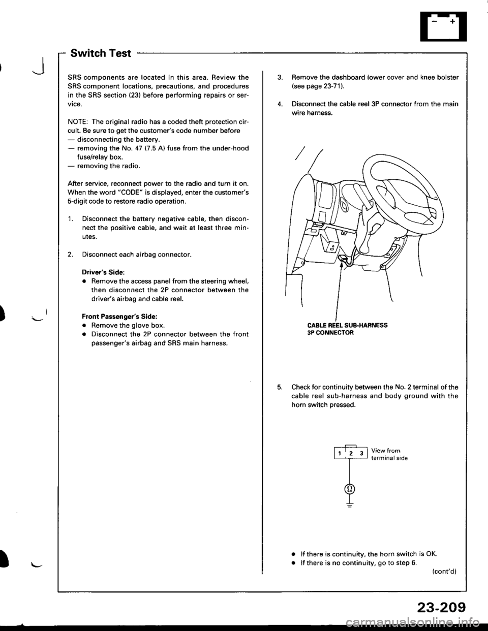
SwitchTest
SRS comDonents are located in this area. Review the
SRS component locations, precautions, and procedures
in the SRS section (23) before performing repairs or ser-
vtce.
NOTE: The original radio has a coded thett protection cir-
cuit. Be sure to get the customer's code number beJore- disconnecting the battery.- removing the No. 47 (7.5 A) fuse from the under-hood
fuse/relay box.- removing the radio.
After service, reconnect Dower to the radio and turn it on.
When the word "CODE" is displayed, enter the customer's
5-digit code to restore radio operation
Disconnect the battery negative cable, then discon-
nect the positive cable, and wait at least three min-
uIes.
Disconnect each airbag connector.
Driver's Side:
a Remove the access panel from the steering wheel,
then disconnect the 2P connector between the
driver's airbag and cable reel.
Front Passenger's Side:
. Remove the glove box,
a Disconnect the 2P connector between the front
passenger's airbag and SRS main harness.
1.
Remove the dashboard lower cover and knee bolster(see page 23-71).
Disconnect the cable reel 3P conneclor from the main
wtre narness.
CABLE REEL SUB.HARNESS3P CONNECTOR
Check for continuitv between the No. 2 terminal of the
cable reel sub-harness and body ground with the
horn switch Dressed.
terminalside
a
It there is continuity, the horn switch is OK.
lf there is no continuity, go to step 6. (cont,d)
r-P r11 2 3l-t-
I
I\-J
)
I
23-209
Page 1311 of 1681
t
t;
i'l
I
dil
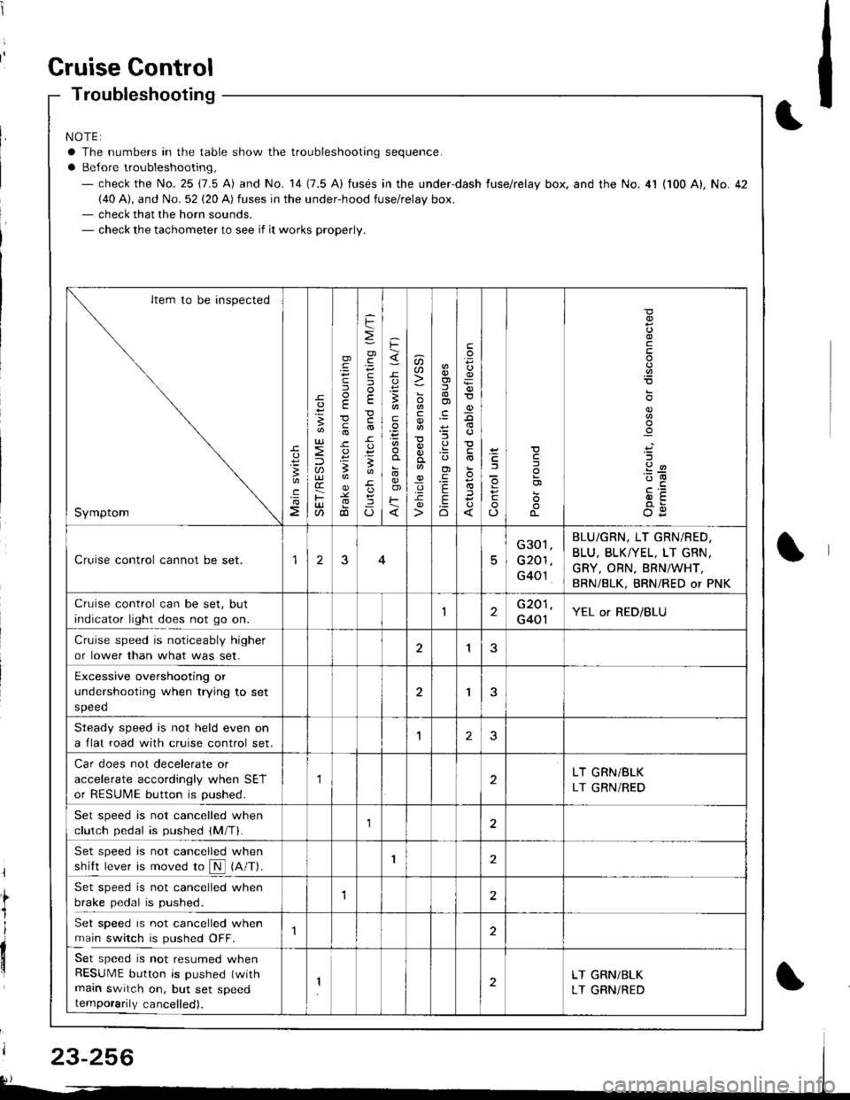
Gruise Gontrol
Troubleshooting
NOTE:
a The numbers in the table show the troubleshooting sequence.
a Belore troubleshooting,- check the No. 25 (7.5 A) and No. 14 (7.5 A) fusds in the under-dash fuse/relay box. and the No. 4l (100 A), No. 42(40 A), and No. 52 (20 A) fuses in the under-hood fuse/relay box.- check that the horn sounds.- check the tachometer to see if it works properly.
Item to be inspected
Symptom
c
:3
UJ
lU)(r
F(t
)
E
c
.
F
=
.g
E
-c
!-
Io
F
3
E
o)F
u)U'
co
_q.9-c
o)f,
ol
;l
E
.Eo
F
E
_9
)a
o
o-
o
c
.2
'::-c
OE
Cruise control cannot be set.15
G301
G201
G40't
BLU/GRN, LT GRN/RED.
BLU, BLKTYEL, LT GRN.
GRY, ORN, BRNiWHT,
BRN/BLK, BRNi RED or PNK
Cruise control can be set, but
indicator light does not go on.1G201
G401YEL or RED/BLU
Cruise speed is noticeably higher
or lower than what was set.1
Excessive overshooting or
undershooting when trying to set
speed
'I
Steadv soeed is not held even on
a flat road with cruise control set.1J
Car does not decelerate or
accelerate accordingly when SET
or RESUME button is pushed.
1LT GRN/BLK
LT GRN/RED
Set speed is not cancelled when
clutch pedal is pushed (M/T).1
Set speed is not cancelled when
shift lever is moved ro N (A/T).I
Set speed is not cancelled when
brake pedal is pushed.12
Set speed is not cancelled when
main switch is pushed OFF.
Set speed is not resumed whenRESUME button is pushed (with
main switch on, but set speedtemporarily cancelled).
2LT GRN/BLK
LT GRNiRED
23-256