main relay HONDA INTEGRA 1998 4.G User Guide
[x] Cancel search | Manufacturer: HONDA, Model Year: 1998, Model line: INTEGRA, Model: HONDA INTEGRA 1998 4.GPages: 1681, PDF Size: 54.22 MB
Page 328 of 1681
'*
1i
v3
I
l
i
I
1.
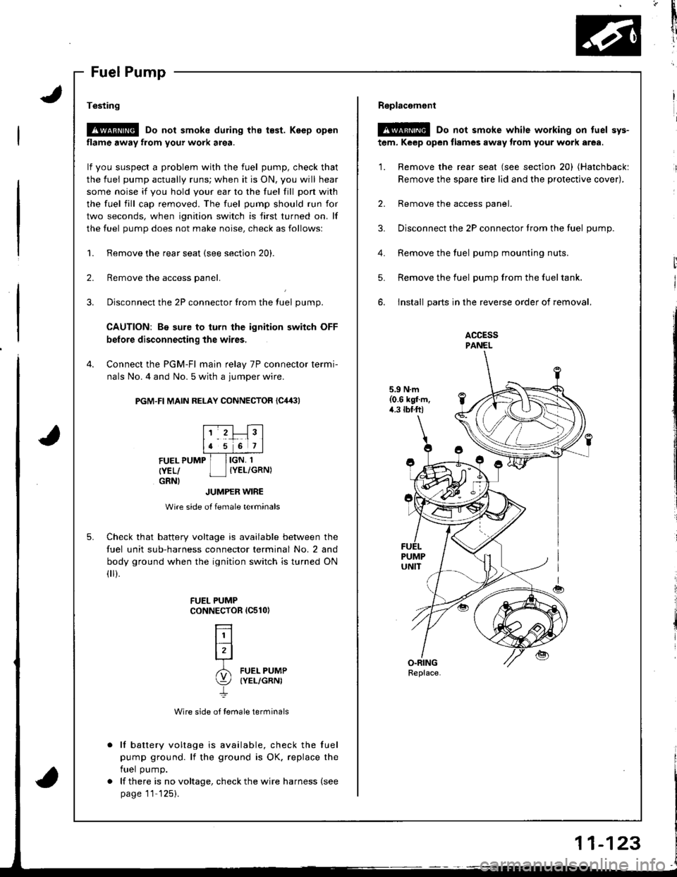
Testing
!@ Do not smoke during tho t€st. Keep open
flame away from your work area.
lf you suspect a problem with the fuel pump, check that
the fuel pump actually runs; when it is ON, you will hear
some noise it you hold your ear to the fuel fill pon with
the fuel fill cap removed. The fuel pump should run for
two seconds, when ignition switch is first turned on. lf
the fuel pump does not make noise, check as followsl
Remove the rear seat (see section 20).
Remove the access panel.
Disconnect the 2P connector from the tuel pump.
CAUTION: Be sure to turn the ignition switch OFF
before disconnecting the wires,
Connect the PGM-Fl main relay 7P connector termi-
nals No. 4 and No. 5 with a jumper wire.
PGM-FI MAIN RELAY CONNECTOR {C,14:}l
2.
3.
4.
5.
FUEL PUMP
{YEL/GRNI
IGN, 1
IYEL/GRN)
JUMPER WIRE
Wire side of female terminals
Check that battery voltage is available between the
fuel unit sub-harness connector terminal No. 2 and
body ground when the ignition switch is turned ON(
).
Wire side of female terminals
lf battery voltage is available, check the fuel
pump ground. lf the ground is OK. replace the
fuel pump.
lf there is no voltage, check the wire harness (see
page 11'125).
FUEL PUMPCoNNECTOR 1C510)
L]l
lrl-r
6l FUEL PUMP
\:/ (YEL/GRNI
4.
Replacemont
@ Do not smoke while working on tuel sys-
tem, Keep open flames away trom your work area.
'1. Remove the rear seat (see section 20) (Hatchbackl
Remove the spare tire lid and the protective cover),
2. Remove the access panel.
3. Disconnect the 2P connector trom the fuel oumD.
Remove the fuel pump mounting nuts.
Remove the fuel pump from the fueltank.
install parts in the reverse order of removal.
ACCESSPANEL
5.9 N.m(0.6 kgl.m,4.3 tbtft)
5.
Replace.
Page 329 of 1681
1L
i
!i
!
{
Fuel Supply System
PGM-Fl Main Relay
Description
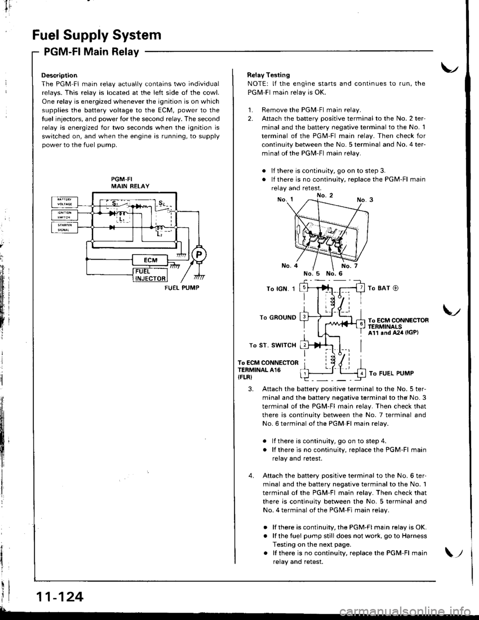
The PGM Fl main relav actuallv contains two individual
relavs. This relav is located at the left side of the cowl.
One relay is energized whenever the ignition is on which
supplies the battery voltage to the ECM, power to the
tuel injectors, and power tor the second relay. The second
relay is energized for two seconds when the ignition is
switched on, and when the engine is running, to supply
power to the fuel pump.
PGM-FIMAIN RELAY
11-124
FUEI- PUMP
Relay Testing
NOTE: lf the engine starts and continues to run, the
PGM-Fl main relay is OK.
1. Remove the PGlvl Fl main relay.
2. Attach the battery positive terminal to the No. 2 ter-
minal and the battery negative terminal to the No. 1
terminal of the PGM-Fl main relay. Then check for
continuity between the No. 5 terminal and No. 4 ter-
minal of the PGN4-Fl main relay.
. lf there is continuity, go on to step 3.
. lf there is no continuity, replace the PGM-Fl main
relay and retest.
To lGN. 1
To GROUND
To ST. SWITCH
To ECM CONNECTORTERMINAL A16
{FLRI
To BAT @
To ECM CONNECTORftNMNALSAll and A24 (lGP)
V
To FUEL PUMP
3. Attach the battery positive terminal to the No. 5 ter-
minal and the battery negative terminal to the No. 3
terminal of the PGM-Fl main relay. Then check that
there is continuity between the No. 7 terminal and
No. 6 terminal of the PGM-Fl main relav.
. lf there is continuity, goon tostep4.
. lf thereis nocontinuity, replacethe PGM-Fl main
relay and retest.
4. Attach the batterv oositive terminal to the No. 6 ter-
minal and the battery negative terminal to the No. 1
terminal ol the PGM-Fl main relay. Then check that
there is continuity between the No. 5 terminal and
No. 4 terminal of the PGM-Fi main relav.
. lf there is continuity, the PGM-FI main relay is OK.
. lf the fuei pumpstill does not work, goto Harness
Testing on the next page.
. lf thereis nocontinuity, replacethe PGM-Fl main
relav and retest.\;
Page 330 of 1681
I
tr,
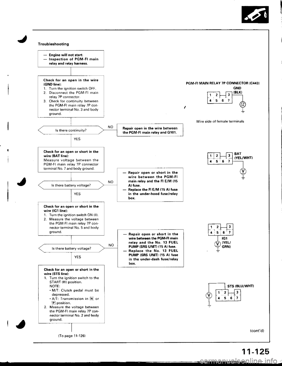
- Engine will not start.- Inspection of PGM-FI mainrelay and relay harne$.
Check lor an open in the ware{GND line}l1. Turn the ignition switch OFF.2. Disconnect the PGM Fl mainrelay 7P connector.3. Check for continuity betweenthe PGM'FI main relay 7P connector terminal No. 3 and bodyground,
Repair open in the wire betweenthe PGM-Fl main relay and G101.
Check for an open or shon in thewire {BAT line)rMeasure voltage between thePGM-Fl main relay 7P connectorterminal No.7 and body ground.- Fepaii open or short in thewire between the PGM-FImain rel6y and the Fl E/M 115A) tuse.- Replace th€ Fl E/M {15 A)fusein the under-hood tuse/relay
ls there battery vohage?
Check foi an open or shori in thewire (lG1 line):1. Turn the ignition switch ON (ll).
2, Measure the voltage betweenthe PGM Fl main relay 7P con-nector terminal No. 5 and bodyground,R€pair open or short in thewire betwo€n the PIGM-FI mainrelav and the No. 13 FUELPUMP ISRS UNIT) (15 Altuse.ReDlace the No. 13 FUELPUMP ISRS UNID (15 Al fusein the under-dash tuse/relayoox,
Check for an open or short in thewire {STS linel:1. Turn the ignition switch to theSTART { lll) position.NOTE:. M/T: Clutch pedal must beoepresseo.. A/T: Transmission in ld or
E position.2. Measure the voltage betweenthe PGM-FI main relay 7P con-nector terminal No. 2 and bodyground,
Troubleshooting
'l RELAY 7P CONNECTOR
GND
t .--.-l T;-l IBLK)L' 'r I" T----
lr s o rl A
+
Wire side o{ female termanals
8AT(YEL/WHT)
STS {BLU/WHTI
(cont'd)
(To page11- t 26)
11-125
Page 331 of 1681
F
I
Fuel Supply
PGM-Fl Main
System
Relay (cont'd)
\
lb
i
(From page 11 125)
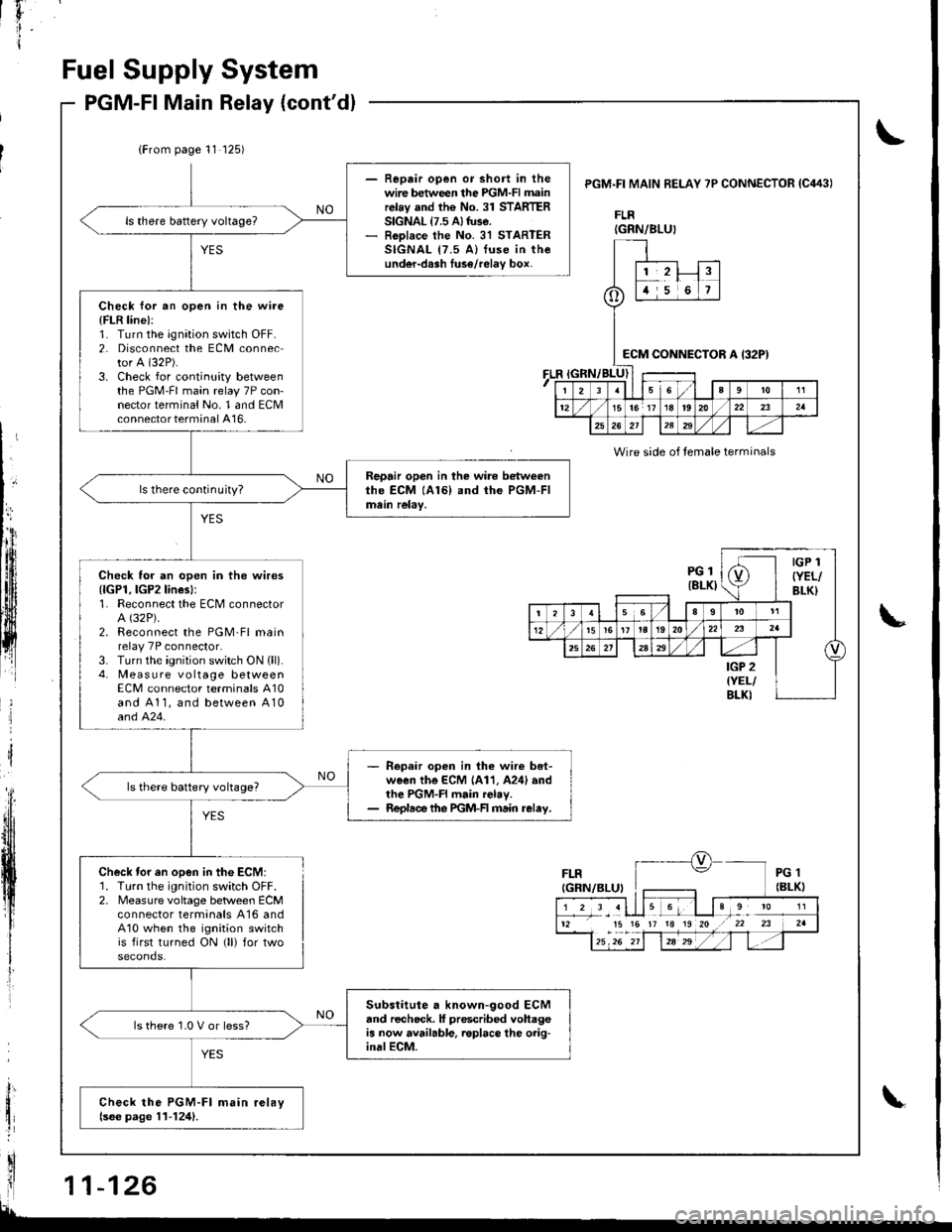
- Reprir open or short in thewire between the PGM-FI mainrelay and the No. 31 STARTERSIGNAL {7.5 A} tuse.- RoDlace the No. 31 STARTERSIGNAL {7.5 A) fuse in theunder-dash luse/relav box,
Check for an open in the wire
{FLR line}:1. Turn the ignation switch OFF.2. Disconnect the ECM connector A (32P).
3. Check for continuity betweenthe PGM-FI main relay 7P con-nector terminal No. 1 and ECMconnector terminal A16-
Repair open in the wire betweenthe ECM (A161 and the PGM-FImein relay,ls there continuity?
Check for an open in the wires{lGPl, lGP2lines}:1. Reconnect the ECM connectorA (32P).
2. Reconnect the PGM-Fl mainrelay 7P connector.3. Turn the ignition switch ON {ll).4. Measure vo ltage betweenECM connector terminals A10and A11, and between A10and 424.
- Repaar open in lhe wir€ bet-ween the ECM 1A11, A24l andthe PGM-FI main relay.- Repldce the PGM-FI main relay.
ls there battery voltage?
Substitute a known-good ECMand recheck. It prescribed vohageis now available. roplace lhe o.ig-inalECM.
ls there 1.0 V or less?
Check the PGM-Fl main relaylsee page 11-124).
PGM.FI MAIN BELAY 7P CONNECTOR IC443I
FLR
FLR
Wire side of temale terminals
Check tor en open in the ECM:1. Turn the ignition switch OFF.2. Measure voltage betlveen ECMconnector termanals A16 andA10 when the ignition switchis first turned ON (ll) for two
IGRN/BLU}
o
1,2!t5i6
:cM CONNEi)TOR A I32P)
I23sl6a9to11
1215lor 17 18t920/22232a
25262l12329
PGl(8LKI
IGP 1
{YEL/BLK}
(
t356I
t5161t la192022
25a
IGP 2{YEL/BLKI
12 15 15 17 18 19 20 .r 22 23
Page 346 of 1681
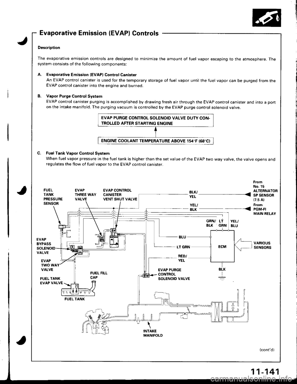
Evaporative Emission (EVAP) Controls
,J
a
DescriDtion
The evaporative emission controls are designed to minimize the amount of luel vapor escaping to the atmosphere. Thesystem consists of the following components:
A. EvaporativeEmission lEVAPlControlCanister
An EVAP control canister is used for the temporary storage of fuel vapor until the fuel vapor can be purged from theEVAP control canister into the engine and burned.
B. Vapol Purge Control System
EVAP control canister purging is accomplished by drawing fresh air through the EVAP control canister and into a pon
on the intake manifold. The purging vacuum is controlled by the EVAP purge control solenoid valve.
C. Fuel Tank Vapor Control System
When fuel vapor pressure in the fuel tank is higher than the set value of the EVAP two way valve, the varve opens anoregulates the flow of fuel vapor to the EVAP control canister.
FrcmNo. 15FUELTANKPRESSURESENSOR
EVAPTHREE WAYVALVE
EVAP CONTROLCANISTENVENT SHUT VALVE
YEL/- BLK
EVAPBYPASSSOLENOIDVALVE
LT GRN
RED/EVAPTWO WAYVALVE
FUEL TANKEVAP VALVE
FUEL TANK
EVAP PURGE CONTROL SOLENOID VALVE DUTY CON-
TROLLED AFTER STARTING ENGINE
?!l ---- 311'AiS-*(7.s Al
FromPGM.FIMAIN RELAY
VARIOUSSENSORS
----<
YEL
EVAP PURGECONTROLSOLENOID VALVE
(cont'd)
-141
Page 466 of 1681
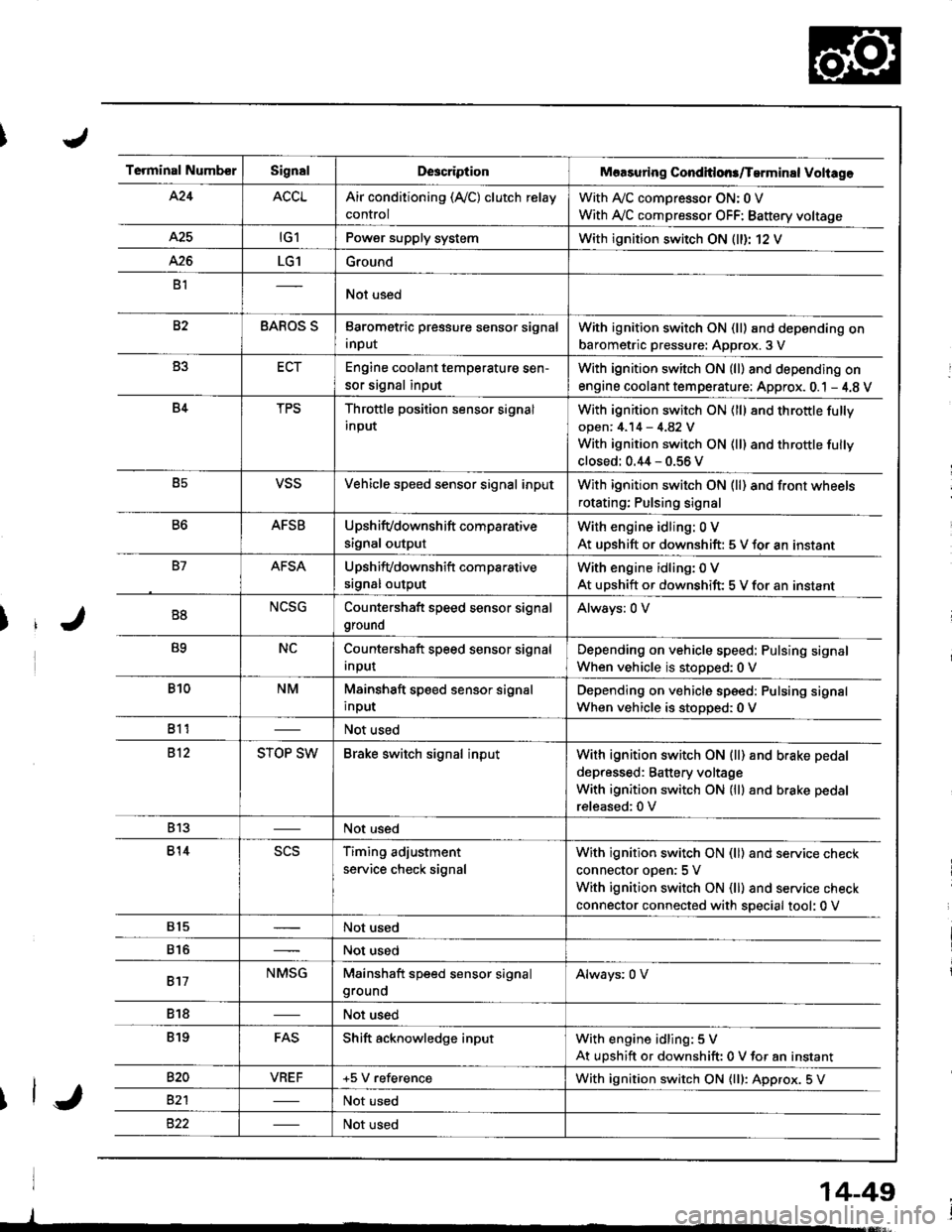
Terminal NumberSignalDescriptionMaasuring Conditlons/Tarminal Voliage
424ACCLAir conditioning (Ay'C) clutch relay
control
With A,/C comDressor ON: 0 V
With Ay'C compressor OFF: Battery voltage
A25tG1Power supply systemWith ignition switch ON (ll)r 12 V
426LG1Ground
B1Not used
82BAROS SBarometric pressure sensor signal
input
With ignition switch ON (ll) and depending on
barometric pressure: Approx. 3 V
B3ECTEngine coolant temperature sen-
sor signal input
With ignition switch ON (ll) and depending on
engine coolant tem perature: Approx. 0.1 - 4.8 V
B4TPSThrottle position sensor signal
input
With ignition switch ON (ll) 8nd throttle fully
open: 4.14 - 4.82 V
With ignition switch ON (ll) and throttle fully
closed: 0.44 - 0.56 V
B5VSSVehicle speed sensor signal inputWith ignition switch ON (ll) and front wheels
rotating; Pulsing signal
B6AFSBUpshifvdownshift comparative
signal output
With engine idling: 0 V
At uDshift or downshift: 5 V for an instant
B7AFSAUpshifvdownshift com parative
srgnal output
With engine idling: 0 V
At upshift or downshift: 5 V for an instant
B8NCSGCountershaft speed sensor signal
ground
Always: 0 V
B9NCCountershaft speed sensor signal
Input
Depending on vehicle speed: Pulsing signal
When vehicle is stopped:0 V
B10NMMainshaft speed sensor signal
input
Depending on vehicle speed: Pulsing signal
When vehicle is stoDoed: 0 V
811Not used
812STOP SWBrake switch signal inputWith ignition switch ON {ll) and b.ake pedal
depressed: Battery voltage
With ignition switch ON (lll and brake pedal
released:0 V
813Not used
814scsTiming adjustment
service check signal
With ignition switch ON (ll) and service check
connector oDen:5 V
With ignition switch ON (ll) and service check
connector connected with special tool: 0 V
815Not used
816Not used
817NMSGMainshaft speed sensor signalgroundAlways: 0 V
818Not used
819FASShift acknowledge inputWith engine idling: 5 V
At upshift or downshift: 0 V for an instant
820VBEF+5 V referenceWith ignition switch ON {lll: Approx. 5 V
82'lNot used
Not used
14-49
Page 472 of 1681
u.drrf,,
J
J
J
14-55
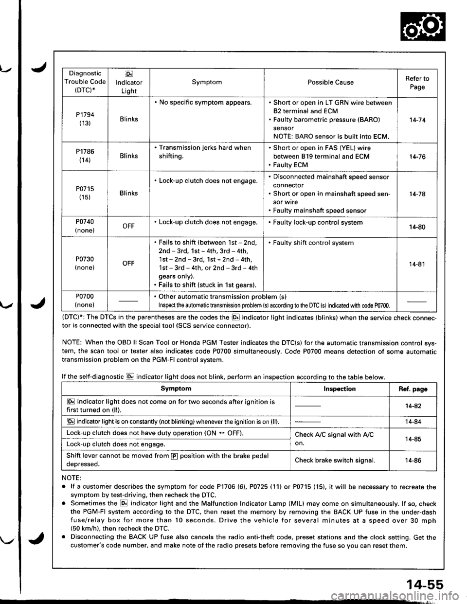
Diagnostic
Trouble Code(DTC).
Ej
lndicator
Light
SymptomPossible CauseRefer to
Page
P1794
(131Blinks
. No specific symptom appears.. Short or open in LT GRN wire between
82 terminal and ECM. Faulty barometric pressure (BARO)
sensor
NOTE: BARO sensor is built into ECM.
't 4-7 4
P1786
(14)Blinks
. Transmission jerks hard when
shifting.
Short or open in FAS (YEL) wire
between 819 terminal and ECM
Faulty ECM
14-76
P0715
(15)Blinks
. Lock-up clutch does not engage,Disconnected mainshaft speed sensor
connector
Short or open in mainshaft speed sen-
sor wrre
Faulty mainshaft speed senso.
14-74
P0740
{ none,OFF. Lock-up clutch does not engage.Faulty lock-up control system14-80
P0730
I none,
. Fails to shift (between lst - 2nd,
2nd - 3rd, 1st - 4th. 3rd - 4th,
1st - 2nd - 3rd, 1st - 2nd - 4th,
1st - 3rd - 4th, or 2nd - 3rd - 4th
gears onry).. Fails to shift (stuck in 1st gears).
. Faulty shift control system
14-81
P0700
(none)
. Other automatic transmission problem (s)
Inspeclthe a utomatic transmission problem (s)accordingto the DTC (s)indicated with code m700.
(DTC)*: The DTCS in the parentheses are the codes the E indicator light indicates (blinks) when the service cnecK connec-tor is connected with the sDecialtool {SCS service connector).
NOTE: WhentheOBDll Scan Tool orHonda PGM Tester indicates the DTC(S) for the automatic transmission control sys-
tem, the scan tool or tester also indicates code P0700 simultaneously. Code P0700 means detection of some automatic
transmission problem on the PGM-Fl control system.
lf the self-diagnostic E indicator light does not blink. perform an inspection according to the table below.
NOTE:
. lf a custombr describes the symptom for code P1706 (6), P0725 (11) or P0715 (15), it will be necessary to recreate the
symptom by test-driving, then recheck the DTC,. Sometimes the E indicator light and the Malfunction Indicator Lamp (MlL) may come on simultaneously. lf so, check
the PGM-Fl system according to the DTC, then reset the memory by removing the BACK UP fuse in the under-dash
fuse/relay box for more than l0 seconds. Drive the vehicle for several minutes at a speed over 30 mph(50 km/h). then recheck the DTC.
. Disconnecting the BACK UP fuse also cancels the radio anti-theft code, preset stations and the clock setting. Get the
customer's code number, and make note of the radio presets before removing the fuse so you can reset them.
SymptomInspectionR€f. page
E indicator light does not come on for two seconds after ignition is
first turned on (ll).14-42
E indicator light is on constantly (not blinking) wheneverthe ignition is on {ll).14-84
Lock-up clutch does not have duty operation (ON - OFF).Check A,/C signal with Ay'C
on.14-85Lock-up clutch does not engage.
Shift lever cannot be moved from E position with the brake pedal
oeDresseo.Check brake switch signal.14-86
Page 682 of 1681
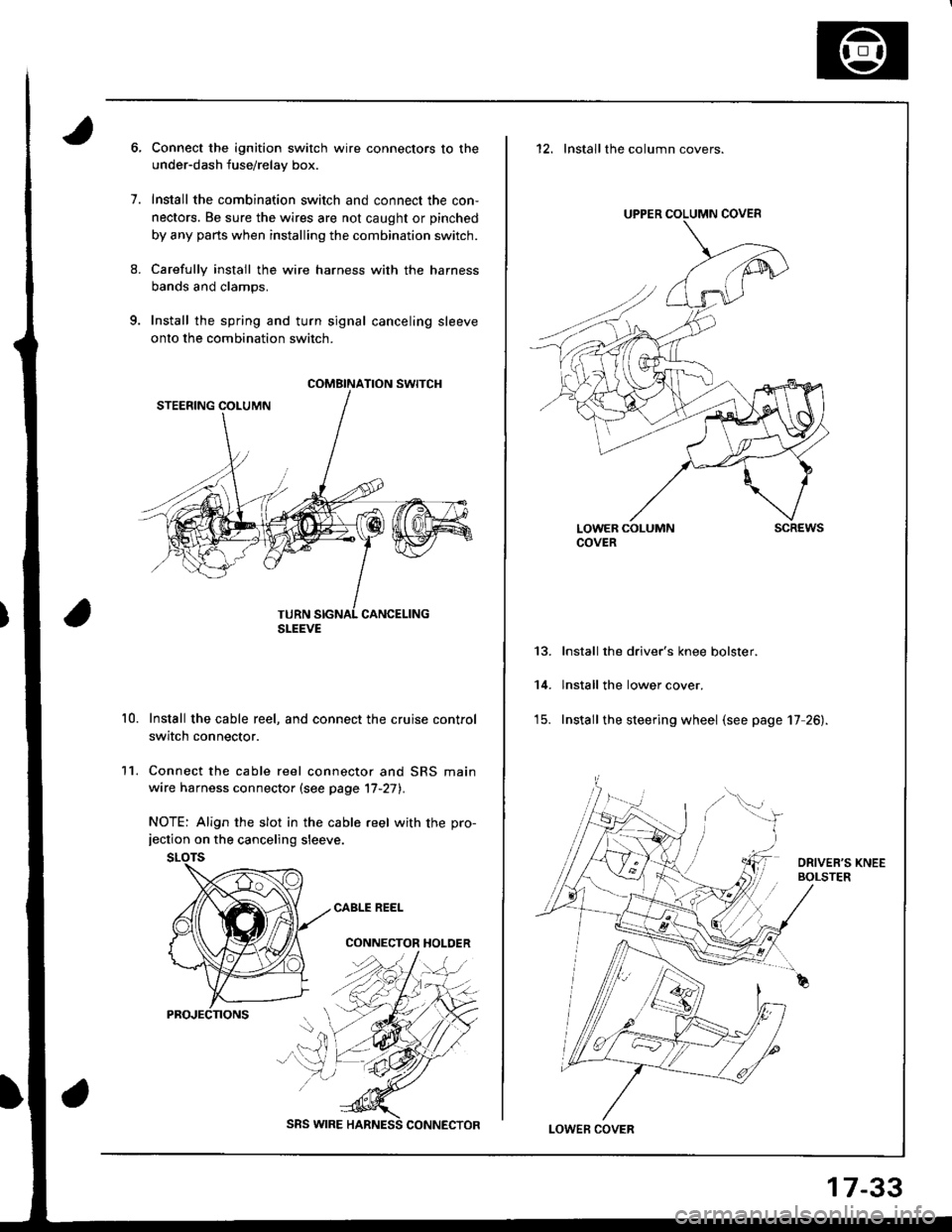
9.
1.
8.
11.
10.
Connect the ignition switch wire connectors to the
under-dash fuse/relay box.
Install the combination switch and connect the con,
nectors. Be sure the wires are not caught or pinched
by any parts when installing the combination switch.
Carefully install the wire harness with the harness
bands and clamps.
Install the spring and turn signal canceling sleeve
onto the combination switch.
Install the cable reel, and connect the cruise control
switch connector.
Connect the cable reel connector and SRS main
wire harness connector (see page '17-27).
NOTE: Align the slot in the cable reel with the pro-jection on the canceling sleeve.
CABLE REEL
CONNECTOR HOLDER
COMBINATION SWITCH
SLEEVE
SRS WIRE
17-33
12. Installthe column covers.
UPPER COLUMN COVER
LOWER COLUMNCOVERscREws
13.
14.
Install the driver's knee bolster.
lnstall the lower cover.
Install the steering wheel (see page 17 26).
LOWEF COVER
Page 953 of 1681
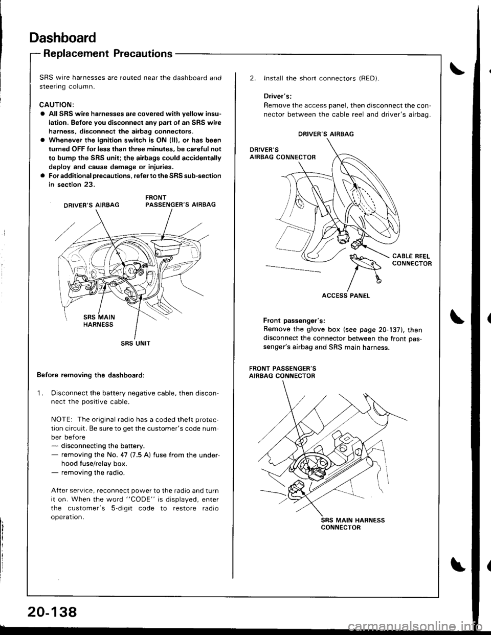
Dashboard
Replacement Precautions
SRS wire harnesses are routed near the dashboard and
steenng column.
CAUTION:
a All SRS wire hsrnesses are covered wiih yellow insu-
lation. Before you disconnect any pan of an SRS wire
harness, disconnect the airbag conneclors.
a Whenever the ignition switch is ON (ll), or has been
tulned OFF for less than three minules, be careful not
to bump the SRS unit; the ai.bags could accidentally
deploy and cause damage or injuries.
a For additional precautions, refer lo the SRS sub-section
in section 23.
PASSENGER'S AIRBAG
Belore removing the dashboard:
1. Disconnect the battery negative cable, then discon-ne.r rhe n^.iriua.ahla
NOTEr The original radio has a coded thett protec,
tion circuit. Be sure to get the customer's code num
ber before- disconnecting the battery.- removing the No. 47 (7.5 A) fuse from the under-
hood tuse/relay box.- removing the radio.
After service, reconnect power to the radio and turn
it on. When the word "CODE" is displayed, enter
the customer's 5-digit code to restore radio
operation.
DRIVER'S AIRBAG
SRS UNIT
20-138
2.Install the short connectors (RED).
Driver's:
Remove the access panel, then disconnect the con-
nector between the cable reel and driver's airbag.
CABL€ REELCONNECTOR--_--._-_-----
Front passenger's:
Remove the glove box (see page 20-137), thendisconnect the connector between the front pas-
senger's airbag and SRS main harness.
FRONT PASSENGER'SAIRBAG CONNECTOR
SRS MAIN HARNESSCONNECTOR
ORIVER'S AIRBAG
Page 1022 of 1681
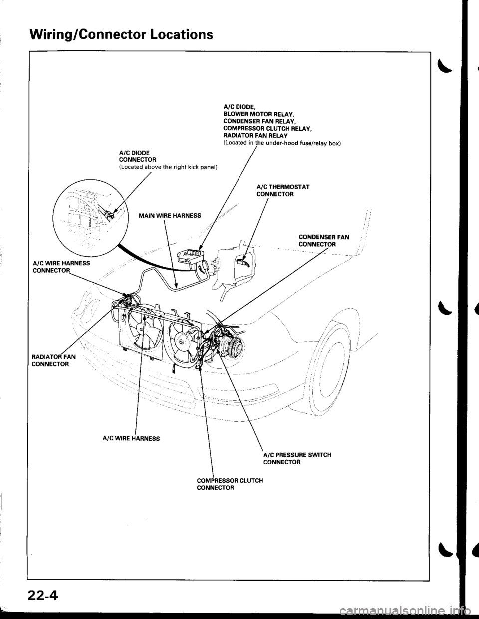
Wiring/Connector Locations
A/C DIODE.BLOWER MOTOR BELAY,CONOENSER FAN RELAY.COMPRESSOR CLUTCH RELAY,RADIATOR FAN REI-AY(Located in the under-hood tuse/relay box)
A/C DIODECONNECTORlLocated above the right kick panel)
MAIN WIBE HARNESS
A/C WINE HARNESS
A/C WIRE HARNESS
A/C PRESSURE SWITCHCONNECTOR
CLUTCHCONNECTOR
22-4