throttle valve HONDA INTEGRA 1998 4.G Service Manual
[x] Cancel search | Manufacturer: HONDA, Model Year: 1998, Model line: INTEGRA, Model: HONDA INTEGRA 1998 4.GPages: 1681, PDF Size: 54.22 MB
Page 530 of 1681
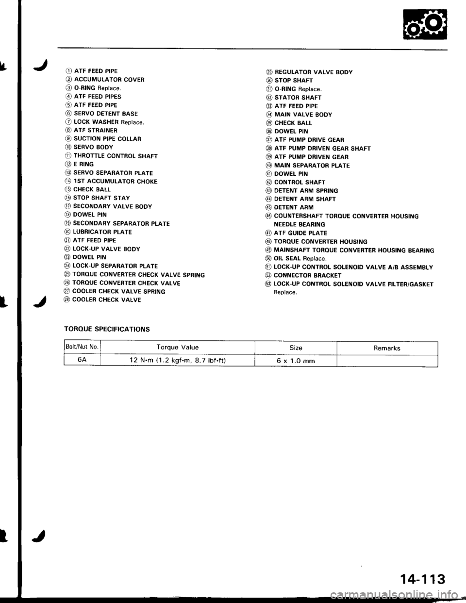
IfD ATF FEED PIPE
O AccUMULAToR covER
@ o-RING Reptace.(O ATF FEED PIPES
(!) ATF FEED PIPE
@ sERvo DETENT BASE
O LocK WASHER Reptace.
[8) ATF STRAINER
@ sucTroN ptpE coLLAR
@ sERVO EODY(, THRoTTLE coNTRoL SHAFT(t E R|NG
Q9 SERVO SEPARATOR PLATE(D 1ST ACCUMULAToR cHoKE
C' CHECK EALL
@ sToP SHAFT STAY
@) SECONDARY VALVE BODY
OO DOWEL PIN
(t SEcoNDARY SEPARAToR PLATE
@ LUBRICAToR PTATE
8] ATF FEED PIPE
@ LocK-uP vALvE BoDy
@ DowEL PrN
@ LocK-uP SEPARAToR PLATE
E TORoUE CoNVERTER cHEcK VALVE SPRING
€0 ToRouE CoNVERTER cHEcK vALvE
Q) COOLER CHECK VALVE SPRING
@ cooLER cHEcK VALVE
TOROUE SPECIFICATIONS
@ REGULAToR vALvE BoDY
@ sToP SHAFT
@ o-RING Reptace.
6, STATOR SHAFT
@ ATF FEED PIPE
@ MA|N VALVE BOOY
@ cHEcK BALL
@ DowEL PrN
@ ATF PUMP DRIVE GEAR
@ ATF PUMP DRIVEN GEAR SHAFT
OO ATF PUMP DRIVEN GEAR
@ MA|N SEPARAToR PLATE
6' DowEL PIN
@ CONTROL SHAFT
@ DETENT ARM SPRING
@ OETENT ARM SHAFT
@ DETENT ARM
@ coUNTERSHAFT ToRoUE coNVERTER HoUSING
NEEOLE BEARING
@ ATF GUIDE PLATE
@ ToRouE coNvERTER HoustNG
@ MAINSHAFT ToRoUE coNvERTER HousING BEARING
@ oll SEAL ReDtace.
@ LocK-up coNTRoL soLENotD vALvE A/B ASSEMBLy
@ coNNEcToR BRACKET
@ LocK-UP coNTRoL SoLENoID vALvE FILTER/GASKET
Replace.
Bolt/Nut No.Torque ValueSizeRemarks
6A12 N.m {1 .2 kgf.m,8.7 lbf.ft)6 x 1.0 mm
I
14-113
Page 547 of 1681
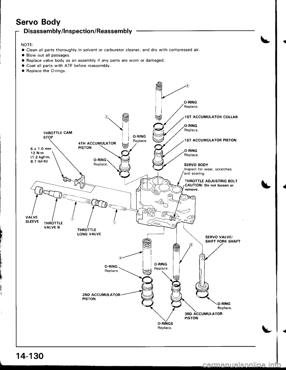
Servo Body
6 x 1.O mm12 N.m{1.2 kgf'm,8.7 tbt.ftl
Disassembly/lnspection/Reassembly
NOTE:
a Clean all parts thoroughly in solvent or carburetor cleaner, and dry with compressed air.
a Blow out all passages.
a Replace valve body as an assembly if any parts are worn or damaged.
a Coat all parts with ATF before reassembly.
a Replace the O-rings.
\9
\l
ll
1ST ACCUMULATOR COLLAR
O.RINGReplace.
1ST ACCUMUI.ATOR PISTON4TH ACCUMULATORPISTON
O.RINGReplace.
Replace.
SERVO BODYInspect for wear, scratchesand sconng.
THROTTLE ADJUSTING BOLTCAUTION: Do not loosen or
VALVE B
--'-'a@':
lll
li
il
14-130
Replace.
{
{a
Page 548 of 1681
I
t
t
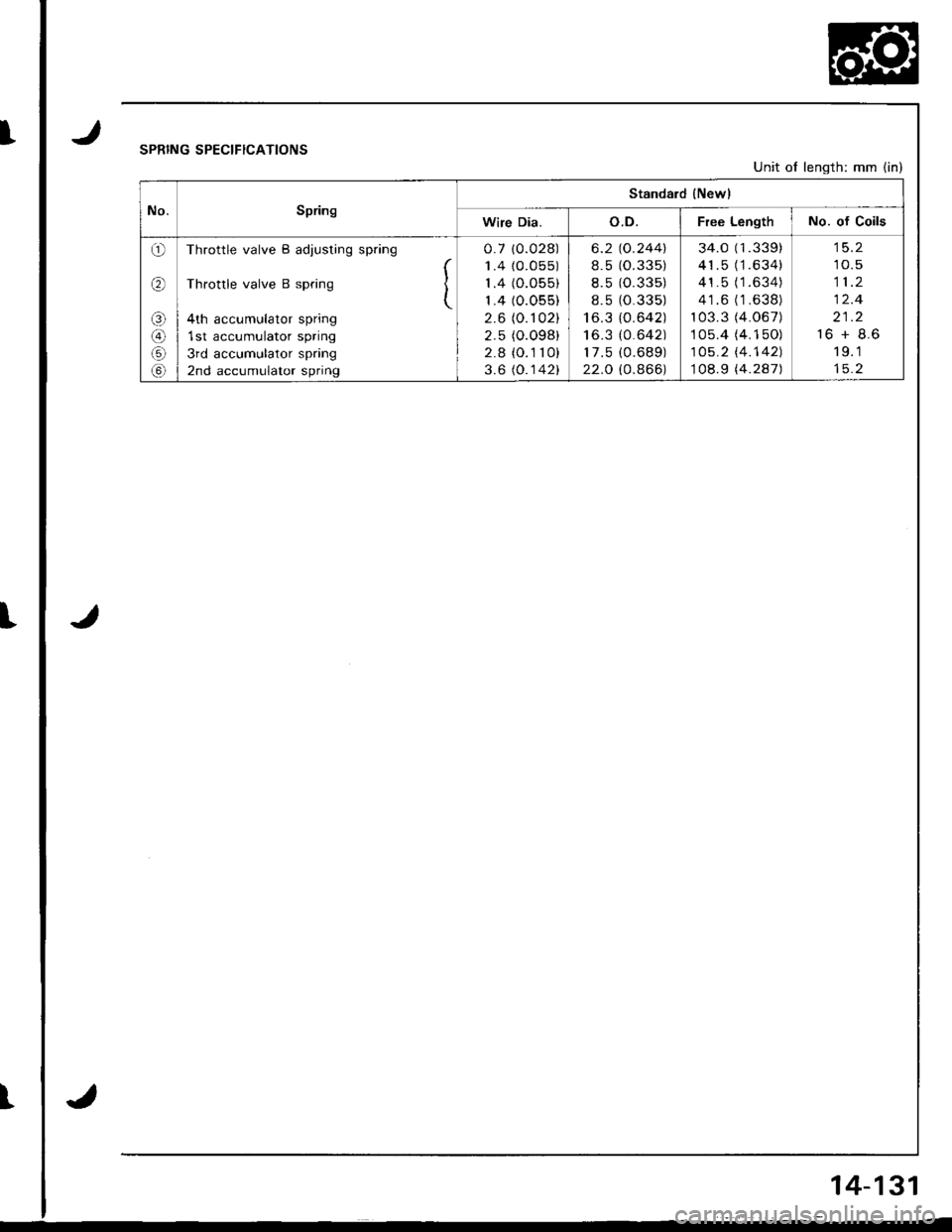
JSPRING SPECIFICATIONS
J
Unit of length: mm (in)
No.Spring
Standard {Newl
Wire Dia.o.D.Free LengthNo. of Coils
o
(r\
o
@
Throttle valve B adjusting spring
Throttle valve B spring I(
4th accumulator spring
1st accumulator spring
3rd accumulator spring
2nd accumulator spring
0.7 10.028)
1.4 {0.055)
1.4 (O.055)
1.4 (0.055)
2.6 (0. r 02)
2.5 (O.098)
2.8 (O.1 10)
3.6 (O.142)
6.2
8.5
8.5
8.5
I o_J
I o.J
17 .5
22.O
"o.244\
1o.33 5)
10.33 5)
1o.33 5)
lo.642)
lo.6421
10.68 9)
lo.866)
34.0 (1.339)
41.5 (1.634)
41.5 (1.634)
41.6 ('1 .638)
103.3 (4.067)
1 05.4 (4. 1 50)
105.2 l'4.142)
108.9 (4.287)
10.5
11.2
12.4
21.2
16 + 8.6
19.1
J
14-131
Page 1073 of 1681
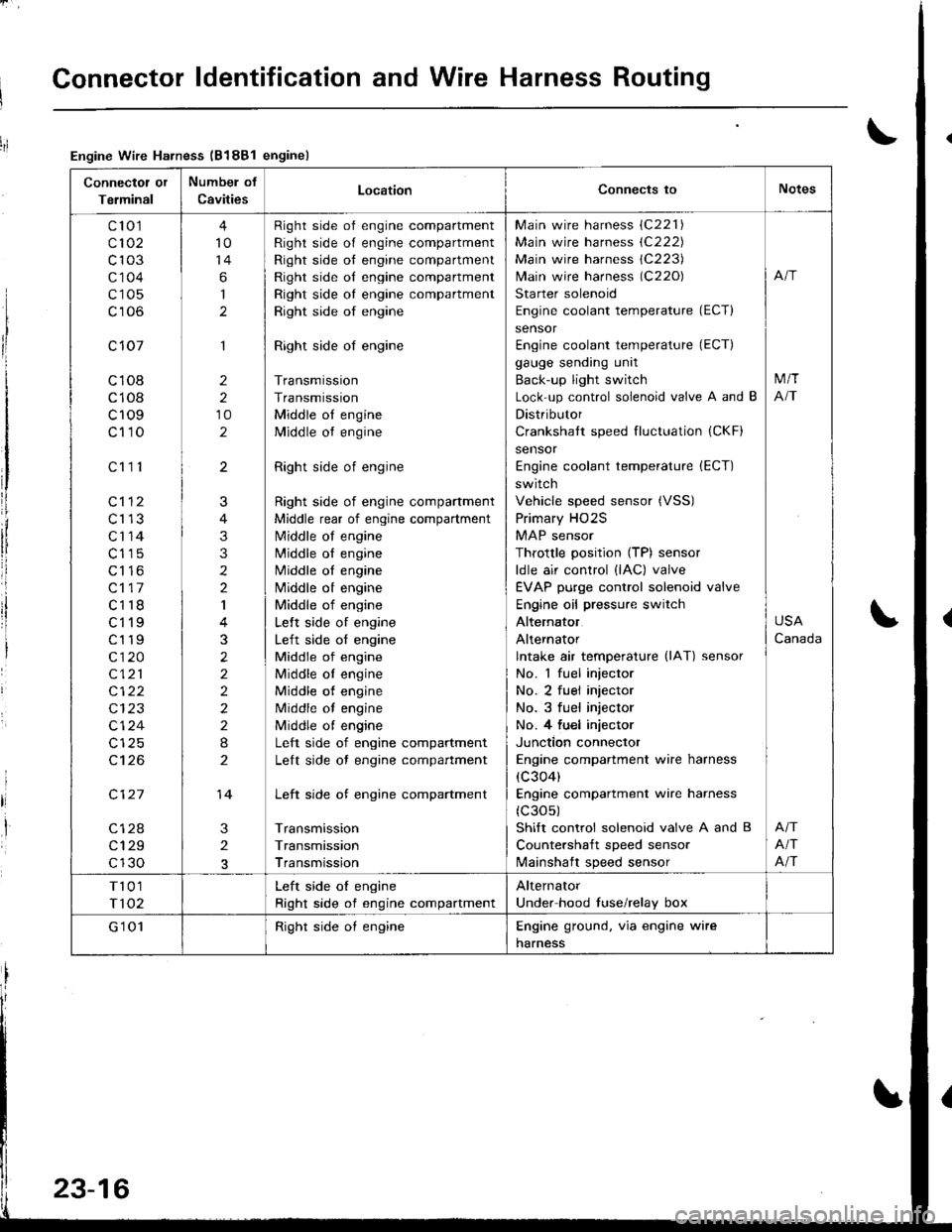
Connector ldentification and Wire Harness Routing
Connectot or
Terminal
Numbel of
CavitiesLocationConnects toNotes
c'to 1
c102
c103
c'1 04
c105
c106
c 107
c108
c108
c109
c110
c112
c113
c'r 14
c115
c116
c117
c118
ct'l9
c119
c120
c121
c122
c124
c't 26
c127
c128
c129
c130
c111
4
10
14
6
I
1
2
2
10
2
3
2
J
4
3
3
2
2
I
3
2
2
2
2
2
I
2
14
Right side of engine compartment
Right side of engine compartment
Right side ot engine compartment
Right side of engine compartment
Right side oI engine compartment
Right side of engine
Right side of engine
Transmission
Transmission
Middle ot engine
Middle ot engine
Right side of engine
Right side of engine compartment
Middle rear of engine compartment
N4iddle of engine
N4iddle ol engine
Middle oI engine
Nliddle ot engine
Middle of engine
Lelt side of engine
Left side of engine
Middle of engine
Middle oI engine
Middle of engine
Middle of engine
Middle ot engine
Left side of engine compartment
Lelt side ot engine compartment
Left side of engine compartment
Transmission
Transmission
Transmission
Main wire harness (C221)
Main wire harness (C222)
Main wire harness 1C223)
lvlain wire harness (C220)
Starter solenoid
Engine coolant temperature (ECT)
sensor
Engine coolant temperature (ECT)
gauge sending unit
Back-up light switch
Lock-up control solenoid valve A and B
Distributor
Crankshatt speed fluctuation (CKF)
sensor
Engine coolant temperature (ECT)
switch
Vehicle speed sensor (VSS)
Primary HO2S
MAP sensor
Throttle position (TP) sensor
ldle air control (lAC) valve
EVAP purge control solenoid valve
Engine oil pressure switch
Alternator
Alternator
lntake air temperature (lAT) sensor
No. 1 fuel injector
No. 2 fuel injector
No. 3 fuel injector
No. 4 fu€l injector
Junction connector
Engine compartment wire harness
(c304)
Engine compartment wire harness
(c30s)
Shift control solenoid valve A and B
Countershaft speed sensor
lvlainshaft speed sensor
M/T
NT
USA
Canada
Afi
Afi
T101
T102
Left side oI engine
Right side of engine compartment
Alternator
Under hood fuse/relay box
G'1 01Right side oI engineEngine ground. via engine wire
harness
Engine Wire Harness (B188l enginel
23-16
Page 1075 of 1681
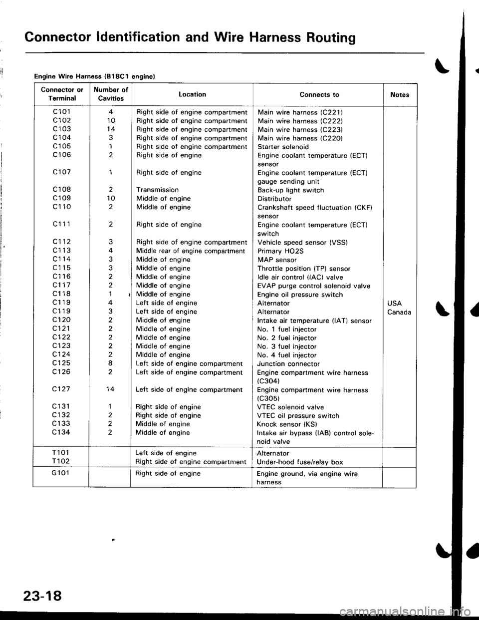
Connector ldentification and Wire Harness Routing
Engine Wire Harness (B18Cl enginel
Connectol ol
Terminal
Number of
CavitiesLocationConnects toNotes
c 101
c102
c103
c104
c105
c106
c101
c108
cr09
c110
c'r 11
cl12
c1't3
c114
c115
c116
cl17
c118
c119
c119
c120
cI2'l
cl24
c126
c127
cl31
c132
c133
c134
10
14
3
1
2
1
2
10
2
'I
3
2
2
2
I
1
2
2
?
3
2
14
Right side of engine compartment
Right side of engine compartment
Right side of engine compartment
Right side ol engine compartment
Right side of engine compartment
Righr side oI engine
Right side of engine
Transmission
Middle of engine
Middle of engine
Right side of engine
Right side of engine compartment
Middle rear of engine compartment
Middle of engine
Middle of engine
Middle of engine
Middle of engine
i/iddle of engine
Left side ot engine
Lelt side ot engine
Middle ot engine
Middle of engine
Middle of engine
Middle of engine
Middle of engine
Left side of engine companment
Left side of engine compartment
Lelt side of engine compartment
Right side of engine
Right side of engine
Middle of engine
Middle of engine
lvlain wire harness (C221 )
Main wire harness {C222)
Main wire harness (C223)
Main wire harness (C220)
Starter solenoid
Engine coolant temperature (ECT)
sensor
Engine coolant temperature (ECT)
gauge sending unit
Back-up light switch
Distributor
Crankshalt speed fluctuation (CKFI
sensor
Engine coolant temperature {ECT)
switch
Vehicle speed sensor (VSS)
Primary HO2S
MAP sensor
Throttle position {TP) sensor
ldle air control (lAC) valve
EVAP purge control solenoid valve
Engine oil pressure switch
Alternator
Alternator
Intake air temperature llAT) sensor
No. 1 fuel injector
No. 2 fuel injector
No. 3 tuel injector
No. 4 tuel injector
Junctron connector
Engine compartment wire harness(c304)
Engine companment wire harness(c30s)
VTEC solenoid valve
VTEC oil pressure switch
Knock sensor (KS)
Intake air bypass {lAB) control sole-
noid valve
USA
Canada
T101
r 102
Left side ot engine
Right side of engine compartment
Alternator
Under-hood fuse/relay box
G 101Right side of engineEngine ground, via engine wire
naaness
23-18
Page 1598 of 1681
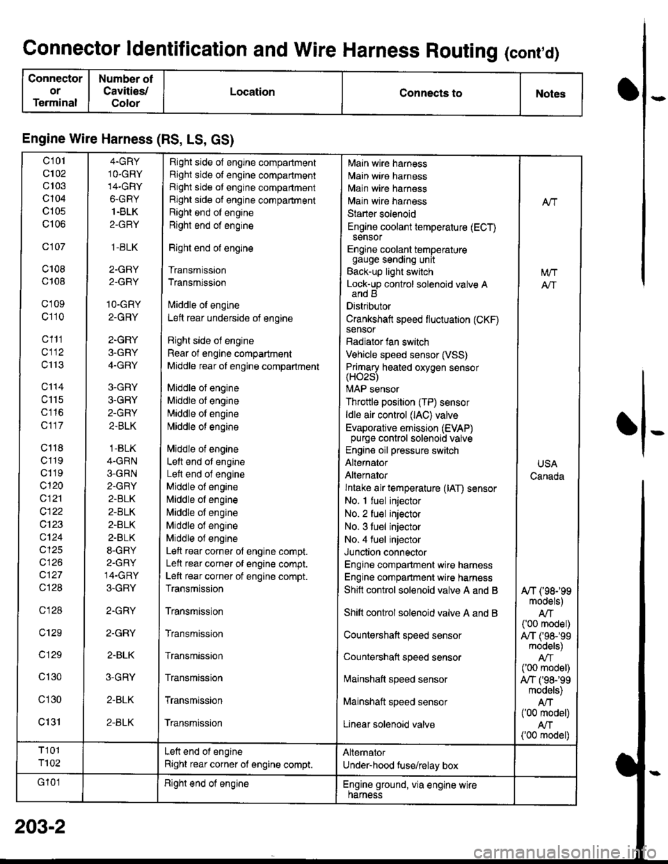
Connector ldentification and Wire Harness Routing (cont,d)
Connector
or
Terminal
Number ot
Cavities/
Color
LocationConnects toNotes
Engine Wire Harness (RS, LS, GS)
c101
c102
c103
c104
c105
c106
c 107
c108
c108
c'1 09
c110
c111
cl12
c113
c'114
c115
c116
c117
c118
c119
c1 19
c120
c121
c122
c123
c124
cl25
cl26
c127
Ql28
c128
c129
c 129
c130
c'l30
c131
4.GRY
1O.GRY
14-GRY
6-GRY
1.BLK
2-GRY
,1-BLK
2-GRY
2.GRY
1O-GRY
2-GRY
2-GRY
3-GRY
4-GRY
3-GRY
3-GRY
2-GRY
2.BLK
.1-BLK
4-GRN
3-GRN
2-GRY
2.BLK
2-BLK
2-BLK
2.BLK
8-GRY
2-GRY
14-GRY
3-GRY
2.GRY
2.GRY
2-BLK
3-GRY
2-BLK
2-BLK
Right side of engine compartment
Right side of engine compartment
Right side ot engine compartment
Right side of engine compartment
Right end of engine
Right end of engine
Right end of engine
Transmission
Transmission
lvliddle ol engine
Lett rear underside of engine
Right side ol engine
Rear of engine compartment
Middle rear ol engine compartment
Middle ol engine
Middle of engine
Middle ol engine
l\4iddle of engine
Middle of engine
Left end ot engine
Lett end of engine
Middle of engine
N,liddle ol engine
Middle of engine
Middle of engine
Middle of engine
Left rear corner of engine compt.
Lelt rear corner of engine compt.
Left rear corner of engine compt.
Transmission
Transmission
Transmission
Transmission
Transmission
Transmission
Transmission
Main wire harness
Main wire harness
Main wire harness
Main wire harness
Starter solenoid
Engine coolant temperature (ECT)sensor
Engine coolant temperaturegauge sending unit
Back-up light switch
Lock-up control solenoid valve Aand B
Distributor
Crankshaft speed fluctuation (CKF)sensor
Radiator fan switch
Vehicle speed sensor (VSS)
Primary heated oxvoen sensor(H02s)
MAP sensor
Throttle position (TP) sensor
ldle air control (lAC) valve
Evaporative emission (EVAP)purge control solenoid valve
Engine oil pressure switch
Alternator
Alternator
Intake air temperature (lAT) sensor
No. I fuel injector
No. 2 fuel injector
No. 3 tuel injector
No. 4 fuel injector
Junction connector
Engine compartment wire harness
Engine compartment wire harness
Shitt control solenoid valve A and B
Shift control solenoid valve A and B
Countershaft speed sensor
Countershatt speed sensor
lvtainshatt speed sensor
Mainshaft speed sensor
Linear solenoid valve
NT
[/VT
A"/T
USA
Canada
A/T (98199models)
AIT('00 model)
A,/T ('98-'�99models)
('00 model)
A,/T f98-'99models)
Atf('00 model)
AN('00 model)
T101
T102
Left end of engine
Right rear corner of engine compt.
Alternator
Under-hood fuse/relay box
G'101Right end ot engineEngine ground, via engine wirenarness
o
I
203-2
Page 1600 of 1681
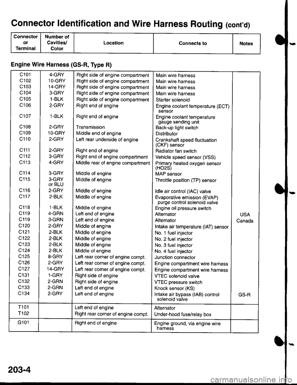
Connector ldentification and Wire Harness Routing (conrd)
Connector
ol
Terminal
Number of
Cavities/
Golor
LocationConnects toNotes
Engine Wire Harness (GS-R, Type R)
c101
c102
c103
c104
U IUC
c106
c107
c108
c109
c110
c111
c112
c113
c114
c115
c116
c117
c118
c11 9
c119
c120
c121
cl22
c123
vtzl
wt10
c127
c131
c132
c133
c134
4-GRY
1O-GRY'I4-GRY
3-GRY
1 -BLK
2-GRY
1.BLK
2-GRY
1O-GRY
2-GRY
2-GRY
3-GRY
4-GRY
3-GRY
3.GRY
or BLU
2-GRY
2-BLK
1 -BLK
4-GRN
3-GRN
2.GRY
2-BLK
2-BLK
2-BLK
2-BLK
8-GRY
2.GRY
14-GRY
1-GRY
2-GRN
2-GRN
2-GRY
Right side of engine compartment
Right side of engine compartment
Bight side of engine compartment
Right side of engine compartment
Right side of engine compartment
Right end of engine
Right end of engine
Transmission
Middle end of engine
Left rear underside of engine
Right end of engine
Right end of engine compartment
Middle rear of engine compartment
Middle of engine
Middle of engine
Middle of engine
Middle of engine
Middle of engine
Left end of engine
Left end of engine
Middle of engine
Middle of engine
Middle of engine
Middle of engine
Middle of engine
Left rear corner of engine compt.
Left rear corner of engine compt.
Left rear corner of engine compt.
Right side of engine
Right side of engine
Left end of engine
Left end of engine
Main wire harness
Main wire harness
Main wire harness
Main wire harness
Starter solenoid
Engine coolant temperature (ECT)
sensor
Engine coolant temperaturegauge sending unit
Back-up light switch
Distributor
Crankshaft speed f luctuation(CKF) sensor
Radiator fan switch
Vehicle speed sensor (VSS)
Primarv heated oxvoen sensor(Hozs)
MAP sensor
Throttle position (TP) sensor
ldle air control (lAC) valve
Evaporative emission (EVAP)purge control solenoid valve
Engine oil pressure switch
Alternator
Alternator
Intake air temperature (lAT) sensor
No. 1 fuel injector
No. 2 fuel injector
No. 3 fuel injector
No. 4 fuel injector
Junction connector
Engine compartment wire harness
Engine compartment wire harness
VTEC solenoid valve
VTEC pressure switch
Knock sensor (KS)
Intake air bypass (lAB) controlsolenoid valve
USA
Canada
GS.R
T101
r102
Left end of engine
Right rear corner of engine compt.
Alternator
Under-hood fuse/relay box
G101Right end of engineEngine ground, via engine wirenarness
203-4
Page 1642 of 1681
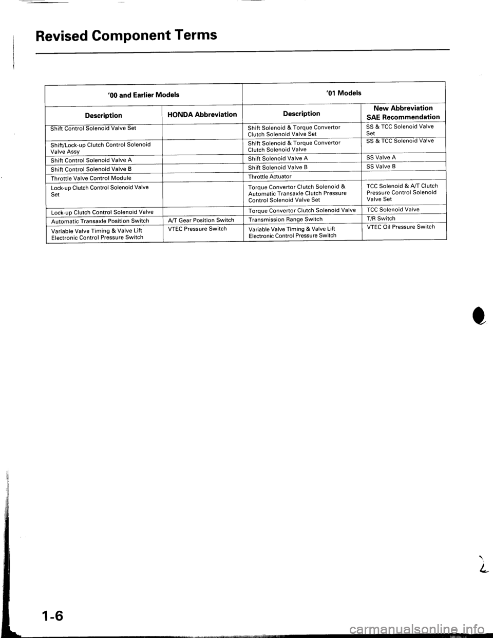
Revised Component Terms
'00 and Earlier Models'01 Models
DescriptionHONDA AbbreviationDescriptionNew Abbreviation
SAE Recommendation
Shift Control Solenoid Valve SetShift Solenoid & Torque ConvertorClutch Solenoid Valve SetSS & TCC Solenoid ValveSet
Shift/Lock-up Clutch Control SolenoidValve Assy
Shift Solenoid & Torque ConvertorClutch Solenoid Valve
SS & TCC Solenoid Valve
Shift Control Solenoid Valve AShift Solenoid Valve ASS Valve A
Shift Control Solenoid Valve BShift Solenoid Valve BSS Valve B
Throttle Valve Control ModuleThroftle Actuator
Lock-uo Clutch Control Solenoid ValveSetToroue Convertor Clutch Solenoid &Automatic Transaxle Cl utch PressureControl Solenoid Valve Set
TCC Solenoid & Av/T ClutchPressure Control SolenoidValve Set
Lock-uo Clutch Control Solenoid ValveTorque Convertor Clutch Solenoid ValveTCC Solenoid Valve
Automatic Transaxle Position SwitchA,/T Gear Position SwitchTransmission Range SwitchT/R Switch
Variable Valve Timing & Valve LiftElectronic Control Pressure Switch
VTEC Pressure SwitchVariable Valve Timing & Valve LiftElectronic Control Pressu re Switch
VTEC Oil Pressure Switch
Page 1644 of 1681
I
I
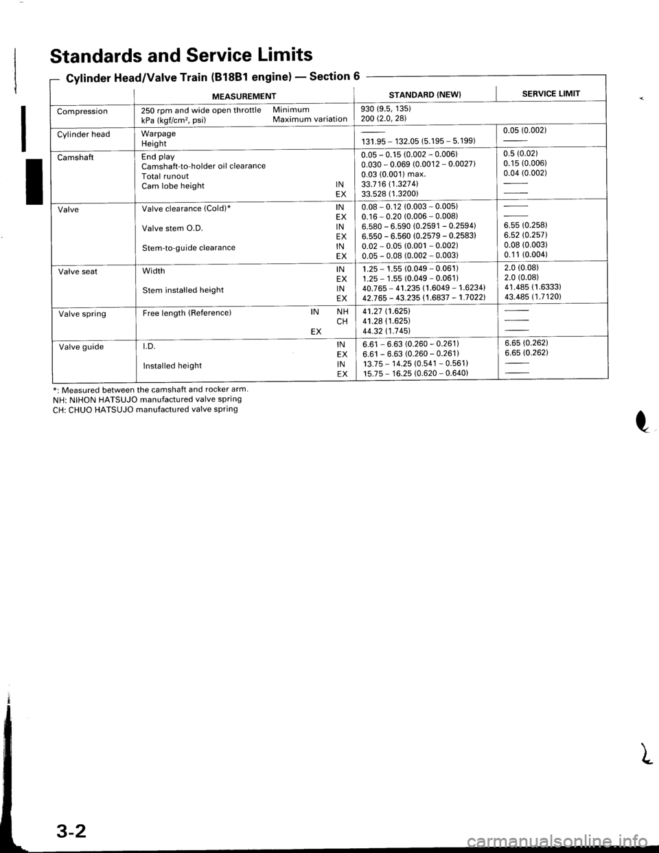
Standards and Service Limits
Cylinder Head/Valve Train (B18Bl engine)Section 6
*: Measured between the camshaft and rocker arm.
NH: NIHON HATSUJO manufactured valve spring
CH: CHUO HATSUJO manufactured valve spring
MEASUREMENTSTANDARD (NEW) I SERVICE LIMIT
Compression250 rpm and wide open throttle Minimum
kPa (kgf/cm'�, psi) Maximum variation930 (9.5, 135)200 Q.0,281
Cylinder headWarpageHeightta,|* - 132.05 (5.195 - 5.199)0.05 (0.002)
CamshaftEnd playCamshaft-to-holder oil clearanceTotal runoutCam lobe height lNEX
0.05 - 0.15 (0.002 - 0.006)0.030 - 0.069 (0.0012 - 0.0027)0.03 (0.001) max.33.7 16 11.327 4l33.528 ( 1.3200)
0.5 (0.02)
0.15 (0.006)
0.04 (0.002)
ValveValve clearance (Cold)" lNEX
Valve stem O.D. lNEX
Stem-to-guide clearance lNEX
0.08 - 0.12 (0.003 - 0.005)0.16 - 0.20 (0.006 - 0.00816.580 - 6.590 (0.2591 - 0.2594)6.550 - 6.560 (0.2579 - 0.2583)
0.02 - 0.05 (0.001 - 0.002)0.05 - 0.08 (0.002 - 0.003)
ouu to.rutt6.52 rc.2571.0.08 (0.003)
0.1 1 (0.004)
Valve seatwidth lNEX
stem installed height lNEX
1 .25 - 1.55 (0.049 - 0.061 )1.25 - 1 .55 (0.049 - 0.061 )40.765 - 41.235 (1.6049 - 1.6234142J65 - 43.235 (1.6837 - 1.70221
2.0 (0.08)
2.0 (0.08)
41.485 (1.6333)
43.485 (1.71201
Valve springFree length (Reference)IN NHCHEX
41.27 (1.6251
41.28 (1.625)
44.32 t1-7 451
Valve guidet.D. lNEX
Installed height lNEX
6.61 - 6.63 (0.260 - 0.261)6.61 - 6.63 (0.260 - 0.261)13.7 5 - 1 4.25 (0.541 - 0.561 )15.75 - 16.25 (0.620 - 0.640)
6.6s (0.262)
6.65 (0.262)
Page 1646 of 1681
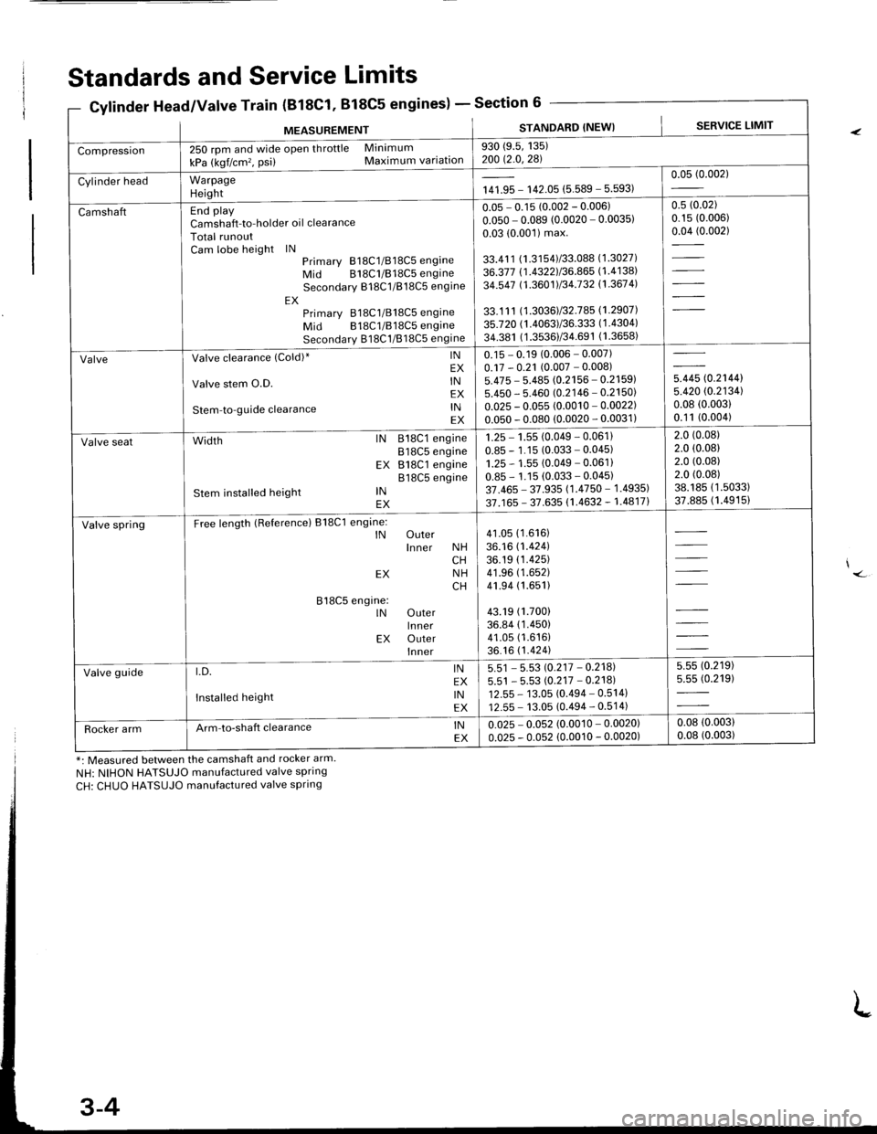
Standards and Service Limits
8C1. 818C5 engines)Section 6Gylinder Head/Valve Train (B'lEC'1,
MEASUREMENTSTANDARD (NEW}SERVICE LIMIT
Compression250 rpm and wide open throttle Minimum
kPa (kgf/cm'�, psi) Maximum variation930 (9.5, 135)200 t2-0,281
Cylinder headWarpageHeightr** - 142.05 (5.589 - 5.593)0.05 (0.002)
CamshaftEnd playCamshaft-to-holder oi I clearanceTotal runoutCam lobe height lNPrimarY 818C1/818C5 engineMid 818C1/818C5 engineSecondarY 818C1/B18C5 engine
EXPrimarv 818C1/818C5 engineMid B18C1/818C5 engineSecondarv B1 8C1/818C5 engine
0.05 - 0.15 (0.002 - 0.006)
0.050 - 0.089 (0.0020 - 0.0035)0.03 (0.001) max.
33.41 1 (1.3154)/33.088 (1.3027)
36.377 (.43221/36.865 (1.4138)
34.547 (1.3601) 134.132 11-367 4l
33.1 1 1 ( 1.3036) 132.7 85 (1.29071
35.720 (1.4063)/36.333 (1.4304)
34.381 (1.3536)/34.691 (1.3658)
0.s (0.02)
0.15 (0.006)
0.04 (0.002)
ValveValve clearance (Cold)* lNEX
Valve stem O.D. lNEX
Stem-to-guide clearance lNEX
0.15 - 0.19 (0.006 - 0.007)0.17 - 0.2't (0.007 - 0.008)5.475 - 5.485 (0.2156 - 0.21595.450 - 5.460 (0.2146 - 0.2150
0.025 - 0.055 (0.0010 - 0.0022
0.050 - 0.080 (0.0020 - 0.0031
in* to.r',ool5.420 (0.2134)
0.08 (0.003)
0.1 1 (0.004)
Valve sealWidth lN 818C1 engineB18C5 engineEX B18C1 engine818C5 engine
Stem installed height lNEX
1.25 - 1.55 (0.049 - 0.061)
0.85 - 1.15 (0.033 - 0.045)1.25 - 1.55 (0.049 - 0.061)0.85 - 1.15 (0.033 - 0.045)37.465 - 37.935 (1.4750 - 1.4935)
37.165 - 37.635 (1.4632 - 1.48171
2.0 (0.08)
2.0 (0.08)
2.0 (0.08)
2.0 (0.08)
38.185 (1.5033)
37.885 (1.4915)
Valve springFree length (Referencel B18C1 engine:lN Outerlnner NHCHEX NHCH
818C5 engine:lN OuterlnnerEX Outerlnner
41.05 (1.616)
36.16 (1.424)
36.19 (1.425)
41 .96 (1.652)
41.94 (1.651)
43.19 (1.700)
36.84 (1 .450)41.05 (1.616)
36.16 (1.424)
Valve guidet.D. lNEX
Installed height lNEX
5"51 - 5.53 {'0.217 -0.2181
5.51 - 5.53 rc.217 - 0.218112.55 - 13.05 (0.494 - 0.5141
12.55 - 13.05 (0.494 - 0.514)
5.55 (0.219)
5.55 (0.219)
Rocker armArm-to-shaft clearance lNEX0.025 - 0.052 (0.0010 - 0.0020)0.025 - 0.052 (0.0010 - 0.0020)0.08 (0.003)
0.08 (0.003)
*: Measured between the camshaft and rocker arm
NH: NIHON HATSUJO manufactured valve spring
CH: CHUO HATSUJO manufactured valve spring