throttle valve HONDA INTEGRA 1998 4.G Owner's Manual
[x] Cancel search | Manufacturer: HONDA, Model Year: 1998, Model line: INTEGRA, Model: HONDA INTEGRA 1998 4.GPages: 1681, PDF Size: 54.22 MB
Page 337 of 1681
In
Intake Air System
Throttle Body
$;
Description
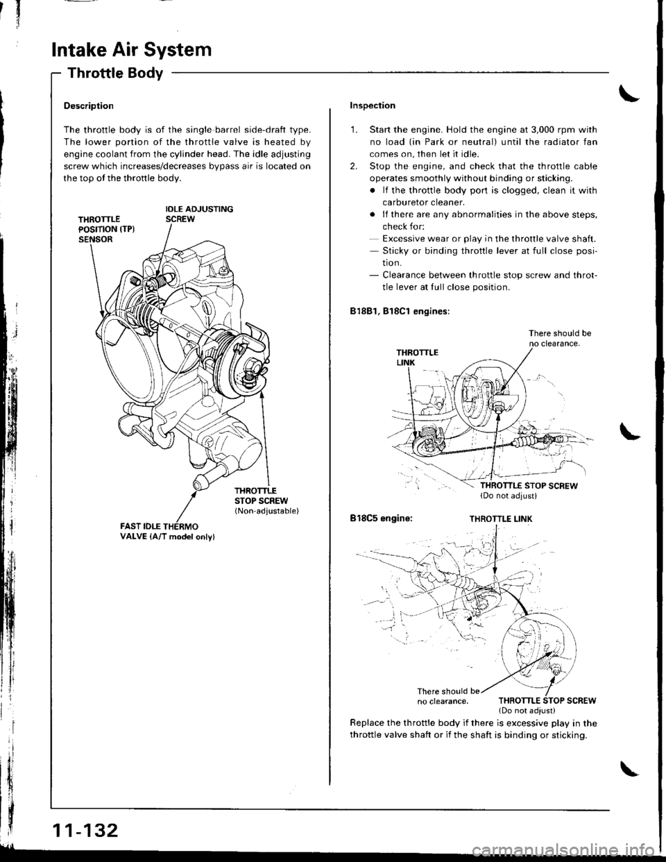
The throttle body is of the single barrel side-draft type.
The lower portion of the throttle valve is heated by
engine coolant from the cylinder head. The idle adjusting
screw which increases/decreases bypass air is located on
the top ot the thronle body.
IDLE ADJUSTINGSCREW
THROTTLESTOP SCREW(Non-adjustable)
FAST IDLE
| | .o clearance. THRoTTLE SToP scREw
{ | | _ .lDonotadiust)
| | y:::::::T,"9":::.'"Tl::f ,::i1::"1" fllyll-'n"
VALVE {A/T model onlv}
Inspection
1. Start the engine. Hold the engine at 3,000 rpm with
no load {in Park or neutral) until the radiator fan
comes on, then let it idle.
2. Stop the engine, and check that the throttle cable
operates smoothly without binding or sticking.
. lf the throttle body pon is clogged, clean it with
carburetor cleaner.
. lf there are any abnormalities in the above steps,
check for:
Excessive wear or play in the throttle valve shaft.- Sticky or binding throttle lever at full close posi-
tion.- Clearance between throttle stop screw and throt-
tle lever at fullclose position.
81881, Bl8Cl engines:
There should beno clearance.
818C5 engine:THROTTLE LINK
There should be
throttle valve shaft or if the shaft is binding or sticking.
glL-
Page 338 of 1681
Disassembly
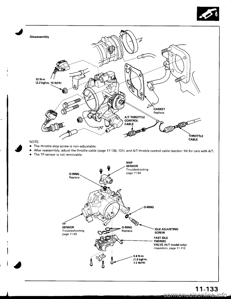
NOTE:
. The throttle stoD screw is non-adiustable.
. After reassembly, adjust the th rottle ca ble (page 11-130, 131),andA/Tthrottlecontrol cable (section l4)Ior cars with A/T.. The TP sensor is not removable.
IOLE ADJUSTINGSCREW
FAST IDLETHERMOVALVE {A/T model onlylInspectaon, page 1 1-l 10
-l
12.2 kgf.m, 16 lbf.ft)
1 1-133
Page 420 of 1681
Description
\J
t{
{
14-3
The automatic transmission is a combination of a 3-element torque converter and triple-shalt electronically controlled
automatic transmission which provides 4 speeds forward and 1 speed reverse. The entire unit is positioned in line with
the engrne.
Torque Converter, Gears, and Clutches
The torque converter consists of a pump, turbine, and stator, assembled in sigle unit. The torque converter is connected to
the engine crankshaft so they turn torether as a unit as the engine turns. Around the outside of the torque convener is a
ring gear which meshes with the starter pinion when the engine is being started. The entire torque converter assembly
serves as a flywheel while transmitting power to the transmission mainshaft.
The transmission has three parallel shafts; the mainshaft. the countershaft, and the sub shaft. The mainshaft is in-line with
the engine crankshaft.
The mainshaft includes the 1st, and 2ndl4th clutches,and gear for 3rd, 2nd, 4th, reverse, and 1st. (3rd gear is integral with
the mainshaft, while reverse gear is integral with the 4th gear.)
The countershaft includes the 3rd clutch and gears for 3rd,2nd, 4th, reverse, 1st, and parking. Reverse and 4th gears can
be loched to the countershaft at its center,providing 4th gear or reverse, depending on which way the selector is moved.
The sub-shaft includes the 1st-hold clutch and gears fo 1st and 4th.
The gears on the mainshaft are in constant mesh with those on the countersahft and sub-shaft.When certain combinations
of gears in the transmission are engaged by clutches. power in transmitted from the mainshaft to the countershaft via the
sub-shaft to orovude oil, lo'1. E, E. and E.
Electronic Control
The electronic control svstem consists of the Transmission Control Module (TCM), sensors, and four solenoid valves.
Shilting and lock-up are electronically controlled for comfortable driving under all conditions.
The TCM is located below the dashboard, behind the lelt side kick panel on the driver's side.
Hydraulic Control
The valve bodies include the main valve body, the secondary valve body, the regulator valve body, the serbvo body, and
the lock-up valve body, through the respective separator plates, They are bolted to the torque converter housing,
The main valve body contains the manual valve, the 1-2 shift valve, the 2-3 shitt valve, the Clutch Pressure Control
lCPC) valve, the 4th exhaust valve, the reliel valve, and the ATF pump gears.
The secondary valve body contains the 4-3 kick-down valve, the 3-2 kick-down valve, the 2-3 orifice control valve, the
3-4 shift valve, the orilice control valve, the modulator valve, and the servo control valve.
The regulator valve body contains the pressure regulator valve, the lock-up control valve, the torque converter check
valve, and the cooler check valve.
The servo body contains the servo valve, which is integrated with shift fork shaft, the throttle valve B, and the accumula-
tors.
The lock-up valve body contains the lock-up shift valve and the lock-up timing B valve, and is bolted to the regulator valve
ooqy.
Fluid from the regulator passes through the manual valve to the various control valves.
Shift Control Mechanism
Input to the TCM from various sensors located throughout the car determines which shift control solenoid valve should
be activated. Activating a shitt control solenoid valve changes modulator pressure, causing a shift valve to move. This
pressurizes a line to one ol the clutches, engaging that clutch and its corresponding gear.
Lock-uD Mechanism
In @ position, in 2nd, 3rd and 4th, and @ position in 3rd, pressurized fluid can be drained lrom the back oI the tor-
que converter through a fluid passage, causing the lock-up piston to be held against the torque converter cover. As this
takes place, the mainshaft rotates at the same speed as the engine crankshaft. Together with hydraulic control, the TCM
optimizes the timing of the lock-up mechanism.
The lock-up valves controlthe range of lock-up according to lock-up control solenoid valves A and B, and throttle valve B.
When lock-up control solenoid valves A and B activate, modulator pressure changes. Lock-up control solenoid valves
A and B are mounted on the torque converter housing, and are controlled by the TCM.
(cont'd)
Page 444 of 1681
Servo Body
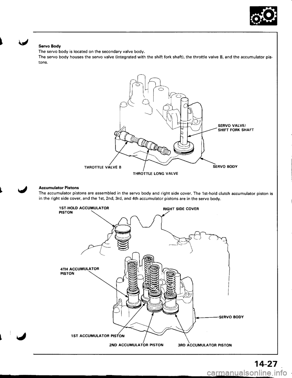
The servo body is located on the secondary valve body.
The servo body houses the servo valve (integrated with the shift fork shaft), the throttle valve B, and the accumulator pis-
tons.
THROTTLE
Accumulator Pistons
The accumulator pistons are assembled in the servo body and right side cover. The 1st-hold clutch accumulator piston is
in the right side cover, and the 1st,2nd,3rd, and 4th accumulator pistons are in the servo bodv.
lST.HOLD ACCUMULATORPISTON
lST ACCUMUI.ATOR
2ND ACCUMULA3RO ACCUMULATOR PISTON
THBOTTLE LONG VALVE
RIGHT SIDE COVER
14-27
Page 445 of 1681
Description
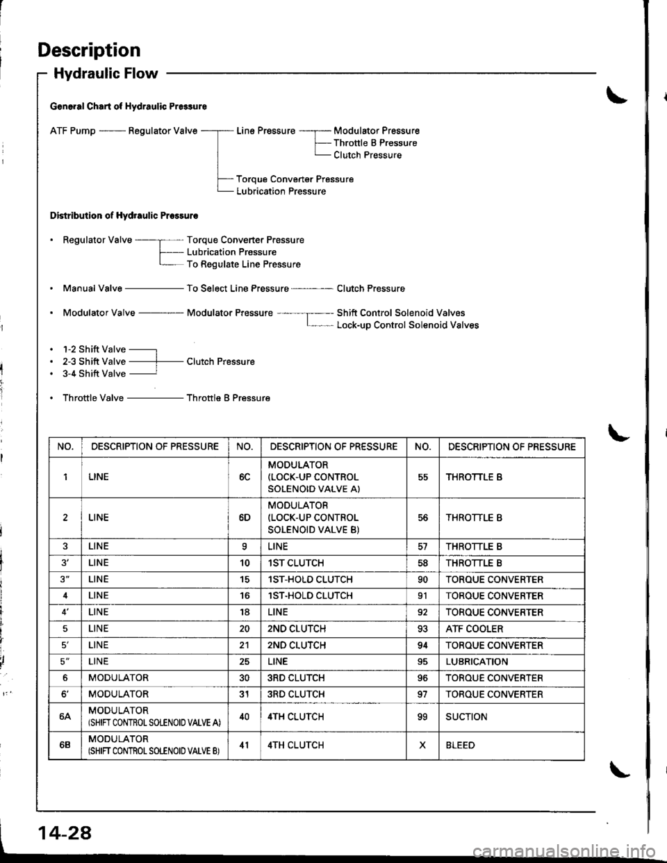
Hydraulic Flow
G€n6.al Chart of Hydraulic Pr6sure
ATF Pump - Regulator Valve
Distribution of Hydraulic Pressuro
Line Pressure -----r- Modulator Pressure
F-- Thronle B PressureL Clutch Pressure
Toroue Convener Pressure
Lubrication Pressure
. Regulator Valve ----; Torque Converter Prossure
f- Lubricaiion PrassureL To Regulate Line Pressure
Manual Valve - To Select Line Pressure - Clutch Pressure
. Modulator Valve Modulator Pressure ---- --I----- Shift Control Solenoid ValvosL- Lock-uD Control Solenoid Valves
. 1-2 Shift Valve -----l
. 2-3 Shift Valve ----f- Clutch Pressure. 3-4 Shift Valve ----------r
. Throttle Valve - Throttle B Pressure
NO,DESCRIPTION OF PRESSURENO.DESCRIPTION OF PR€SSURENO.DESCRIPTION OF PRESSURE
1LINE6C
MODULATOR(LOCK.UP CONTROL
SOLENOID VALVE A)
55THROTTLE B
LINE6D
MODULATOR(LOCK-UP CONTROL
SOLENOID VALVE B)
56THROTTLE B
LINEaLINETHROTTLE B
LINE101ST CLUTCH5dTHROTTLE B
LINE151ST-HOLD CLUTCH90TOROUE CONVERTER
4LINElST.HOLD CLUTCH91TOROUE CONVERTER
LINE18LINE92TOROUE CONVERTER
5LINE202ND CLUTCH93ATF COOLER
LINE212ND CLUTCH94TOROUE CONVERTER
5'LINE25LINELUBRICATION
6MODULATOR303RD CLUTCH96TOROUE CONVERTER
MODULATOR313RD CLUTCH97TOBOUE CONVERTER
64MODULATOR(SHIN CONTROLSOLENOIO VALVE A)404TH CLUTCHooSUCTION
6BMODULATOR(SHIFT CONTROT SOLENOID VATVE B)414TH CLUTCHXBLEED
Page 447 of 1681
Description
Hydraulic Flow (cont'dl
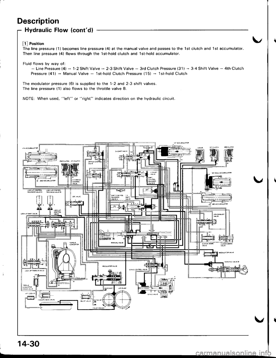
L! l Position
The line pressure ( 1 ) becomes line pressure (4) at the manual valve and passes to the 1st clutch and 1 st accumulator.
Then line pressure (4) llows through the 1st-hold clutch and 1st-hold accumulator.
Fluid flows bv wav of:- Line Pressure (4) - 1-2 Shift Valve - 2-3 Shitt Valve - 3rd Clutch Pressure (31) -- 3-4 Shift Valve - 4th Clutch
Pressure (41) - Manual Valve - lst-hold Clutch Pressure (15) - lsfhold Clutch
The modulator pressure (6) is supplied to the 1-2 and 2-3 shift valves.
The lane Dressure (1) also flows to the throttle valve B.
NOTE: When used, "left" or "right" indicates direction on the hydraulic ci.cuit.
14-30
Page 449 of 1681
Description
Hydraulic Flow {cont'dl
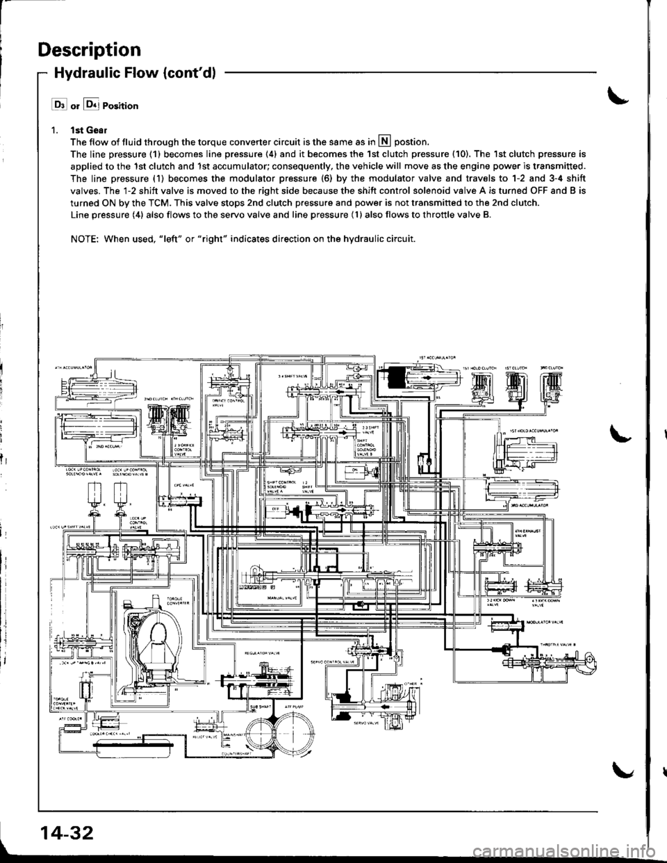
l ll or &j Position
1. lst Geal
The flow of fluid through the torque converter circuit is the same as in lll postion.
The line pressure (1) becomes line pressure (4) and it becomes the 1st clutch pressure (10). The 1st clutch pressure is
applied to the 1st clutch and 1st accumulator; consequently, the vehicle will move as the engine power is transmitted.
The line pressure (1) becomes the modulator pressure (6) by the modulator valve and travels to 1-2 and 3-4 shift
valves. The l-2 shift valve is moved to the right side because the shift control solenoid valve A is turned OFF and B is
turned ON by the TCM. This valve stops 2nd clutch pressure and power is not transmitted to the 2nd clutch.
Line pressure (4) also flows to the servo valve and line pressure (l ) also flows to throttle valve B.
NOTE: When used, "|eft" or "right" indicates direction on the hydraulic circuit.
fr
14-32
Page 456 of 1681
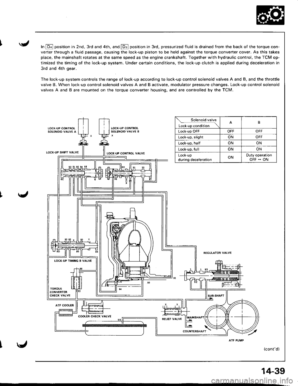
In E position in 2nd, 3rd and 4th, and E position in 3rd, pressurized fluid is drained from rhe back of the torque con-
verter through a fluid passage, causing the lock-up piston to be held against the torque converter cover. As this takes
place, the mainshaft rotates at the same speed as the engine crankshatt. Together with hydraulic control, the TCM op-
timized the timing of the lock-up system. Under certain conditions, the lock-up clutch is applied during deceleration in
3rd and 4th gear.
The lock-up system controls the range of lock-up according to lock-up control solenoid valves A and B, and the throttle
valve B. When lock-up control solenoid valves A and B activate, modulator pressure changes. Lock-up control solenoid
valves A and B are mounted on the torque converter housing. and are controlled by the TCM.
LOCK,UP CONTROL
LOCT.UP SHIfT VALVE
AlF COOIER
tocK uP coNTno! valvE
Solenoid valve
L*r""r "o.Jtio" \B
Lock'up OFFOFFOFF
Lock-up, slightONOFF
Lock-up, halfONON
Lock-up, fullONON
LOCK-Updu.ing decelerationONDuty operationOFF - ON
IOCK UP TIMING B VATVE
(cont'd)
14-39
Page 458 of 1681
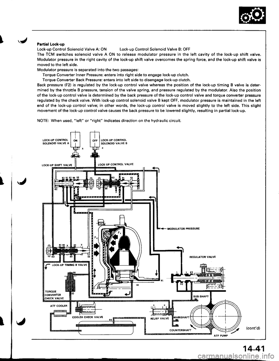
IPartial Lock-up
Lock-uo Control Solenoid Valve A: ONLock-uD Control Solenoid Valve B: OFF
The TCM switches solenoid valve A ON to release modulator Dressure in the left cavity of the lock-up shift valve.
Modulator pressure in the right cavity of the lock-up shift valve overcomes the spring force, 8nd the lock-up shift valve is
moved to the left side,
Modulator pressure is separated into the two passages:
Torque Converter Inner Pressure: enters into right side to engage lock-up clutch,
Torque Converter Back Pressure: enters into left side to disengage lock-up clutch.
Back prassure {F2) is regulated by the lock-up control valve whereas the position of the lock-up timing B valve is deter-
mined by the throttle B pressure, tension of the valve spring, and pressure regulated by the modulator. Also the position
of the lock-up control valve is determined by the back prossure of the lock-up control valve and torque converter pressure
regulated by the check valve. With lock-up control solenoid valve B kept OFF. modulator pressure is maintained in the left
end of the lock-up control valve; in other words, the lock-up control valve is moved slightly to the left side. This slight
movement of the lock-up control valve causes the back pressure to be lowered slightly, resulting in partial lock-up.
NOTE: When used, "|eft" or "right" indicates direction on the hydraulic circuit.
LOCK.UP GO TNOLSOLENOIO VAIVE A
TOCK-UP SHIFT VAIVELOCI( UP COI{TROL VAIVE
T
LOC(,UP IM TG g VALV€
MODULATOB PNESSUFE
14-41
Page 459 of 1681
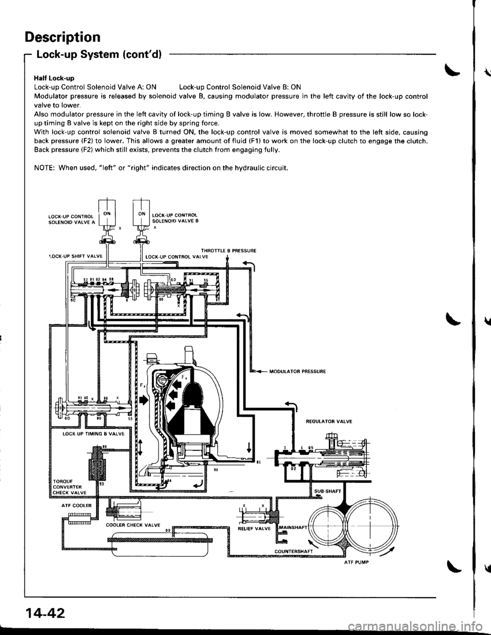
Description
I,OCK UP SHIFT VALVE
Lock-up System (cont'dl
Halt Lock-up
Lock-up Control Solenoid Valve A: ONLock-up Control Solenoid Valve B: ON
Modulator pressure is released by solenoid valve B. causing modulator pressure in the left cavity of the lock-up control
valve to lower.
Also modulator pressure in the left cavity of lock-up timing B valve is low. However, throttle B pressure is still low so lock-
up timing B valve is kept on the right side by spring force.
With lock-up control solenoid valve B turned ON, the lock-up control valve is moved somewhat to the left side, causing
back pressure (F2) to lower. This allows a greater amount of fluid (F1) to work on the lock-up clutch to engage the clutch.
Back pressure (F2) which still exists, prevents the clutch from engaging fully.
NOTE: When used, "|eft" or "right" indicates direction on the hydraulic circuit.
LOCK.UP COI\ITBOL
THROITIE B PRESSUREIOCX UP COIITROL VALVE
MODULATOR PNESSURE
TOCK UP TIMING B VALVE
14-42
\
t
{