throttle valve HONDA INTEGRA 1998 4.G User Guide
[x] Cancel search | Manufacturer: HONDA, Model Year: 1998, Model line: INTEGRA, Model: HONDA INTEGRA 1998 4.GPages: 1681, PDF Size: 54.22 MB
Page 243 of 1681
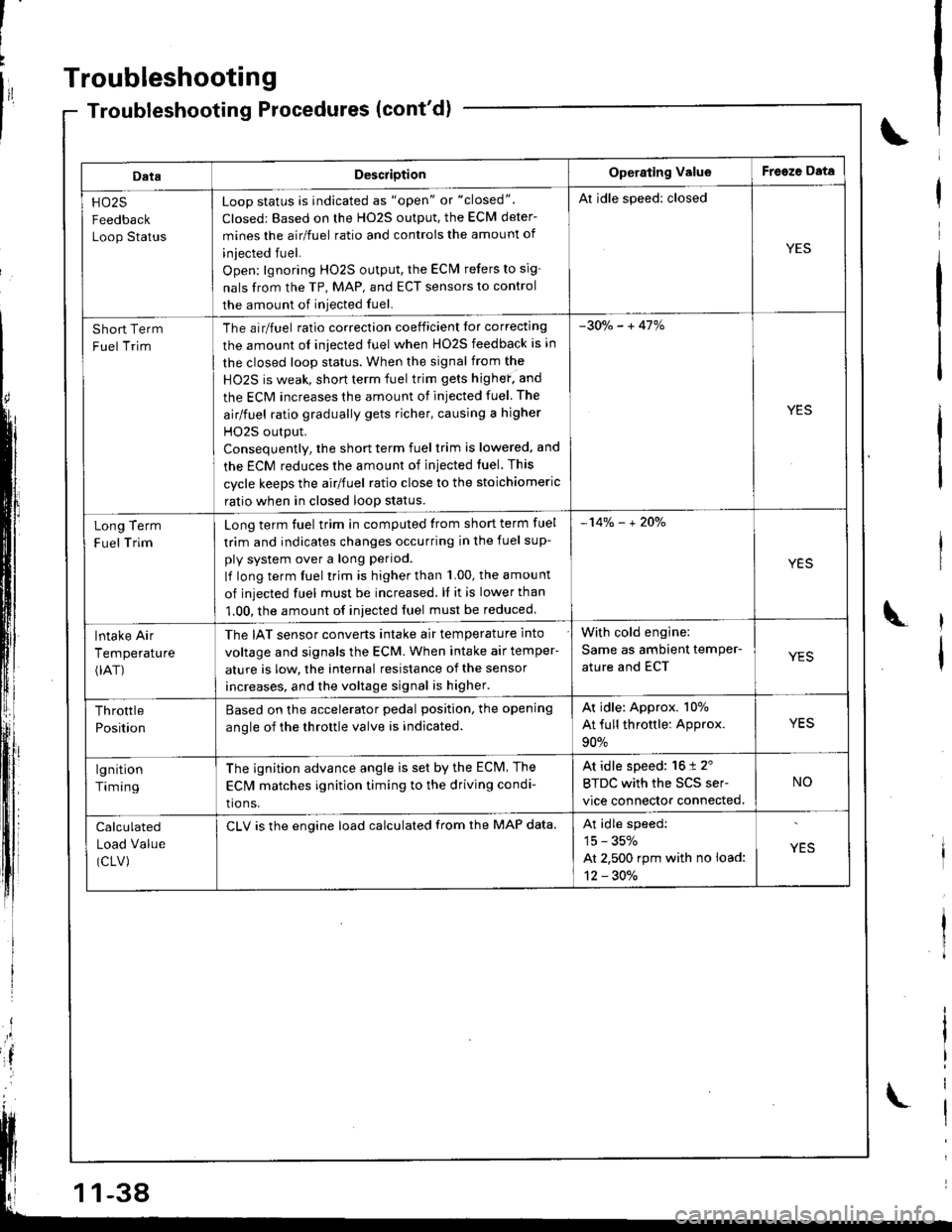
Troubleshooting
DataDescriotionOperating ValueFreeze Data
HO25
Feedback
Loop Status
Loop status is indicated as "open" or "closed".
Closed: Based on the H02S output, the ECM deter-
mines the airlfuel ratio and controis the amount of
iniected fuel.
Open: lgnoring HO2S output, the ECM refers to sig-
nals from the TP, MAP, and ECT sensors to control
the amount of iniected fuel.
Al idle speed: closed
YES
Short Term
Fuel Trim
The airlfuel ratio correclion coeificient lor correcting
the amount ol iniected fuel when HO2S feedback is in
the closed loop status. When the signal from the
HO2S is weak, short term fuel trim gets highef. and
the ECM increases the amount of injected fuel The
airlfuel ratio gradually gets richer, causing a higher
HO2S output.
Consequentlv, the short term fuel trim is lowered, and
the ECM reduces the amount of injected tuel. This
cycle keeps the airlfuel ratio close to the stoichiomeric
ratio when in closed loop status.
-30o/" - + 41%
YES
Term
Trim
Long
F uel
Long term fuel trim in computed trom short term fuel
trim and indicates changes occurring in the fuel sup-
ply system over a long period.
lf long term fuel trim is higher than 1.00, the amou nt
of injected fuel must be increased. ll it is lower than
1.00, the amount of iniected fuel must be reduced
-14% - + 2Oo/"
YES
lntake Air
Temperature(rAT)
The IAT sensor converts intake air temperature into
voltage and signals the ECM. When intake air temper-
ature is low, the internal resistance of the sensor
increases, and the voltage signal is higher.
With cold engine:
Same as ambient temPer-
ature and ECTYES
Throttle
Position
Based on the accelerator pedal position. the opening
anole of the throttle valve is indicated.
Ar idle: Approx. 107o
At full throttle: Approx.
90%
YES
lgnition
Timing
The ignition advance angle is set by the ECM. The
EClvl matches ignition timing to the driving condi-
tio ns.
At idle speed: 16 t 2'
BTDC with the SCS ser-
vice connector connected.
NO
Calculated
Load Value
(CLV)
CLV is the engine load calculated from the MAP data.At idle speedi
15 - 35%
At 2,500 rpm with no load:
12 - 30./.
YES
-38
Page 249 of 1681
Troubleshooting
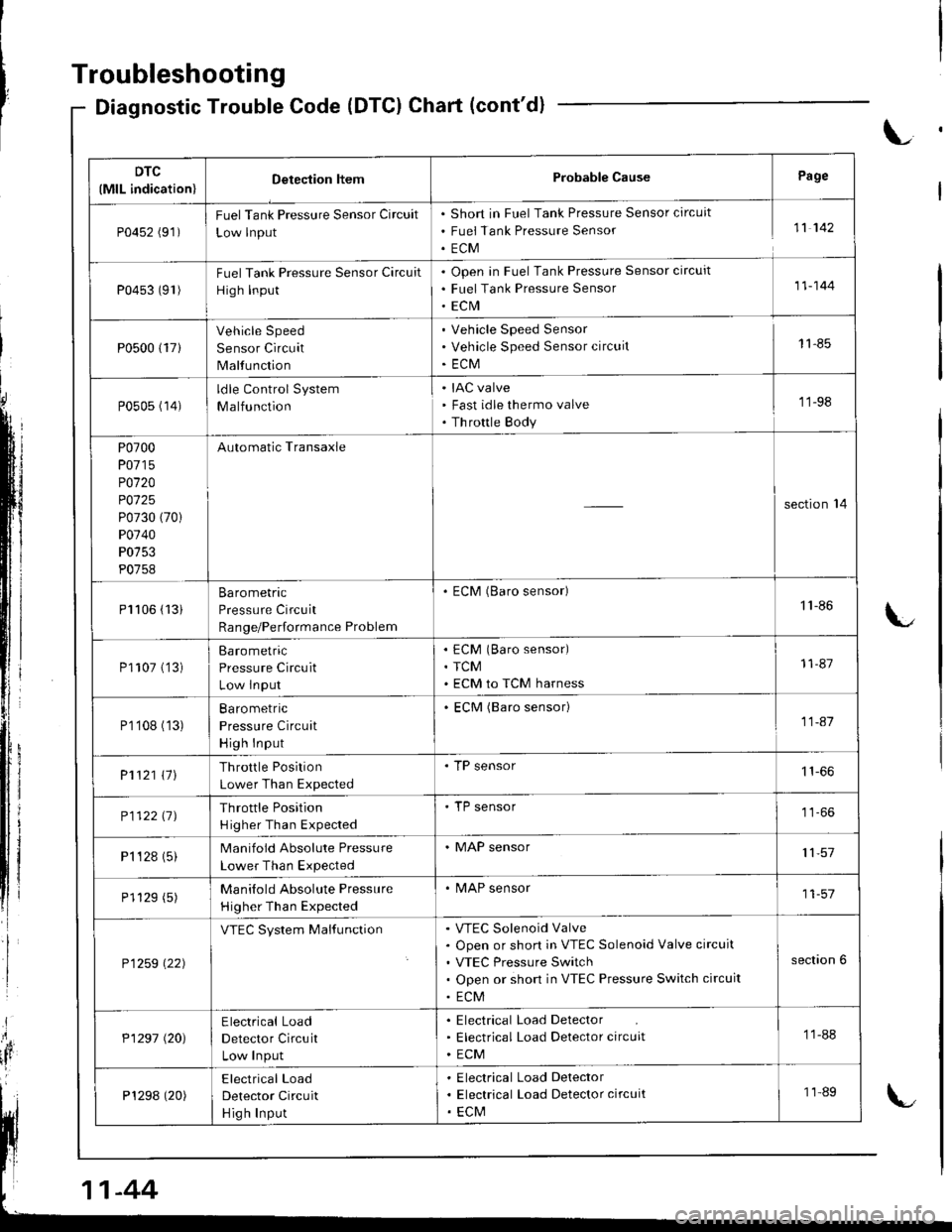
Diagnostic Trouble Code (DTCI Chart (cont'd)
L
DTC
(MlL indication)Detection ltemProbable CausePage
P0452 (91)FuelTank Pressure Sensor Circuit
Low lnput
Short in Fuel Tank Pressure Sensor circuit
Fuei Tank Pressure Sensor
ECM
11 142
P0453 (91)Fuel Tank Pressure Sensor Circuit
High Input
Open in Fuel Tank Pressure Sensor circuit
Fuel Tank Pressure Sensor
ECrVI
11-144
P0500 {17}
Vehicle Speed
Sensor Circuit
Malfunction
Vehicle Speed Sensor
Vehicle Speed Sensor circuit
ECM
11-85
P0505 (14)ldle Control System
Malfunction
IAC valve
Fast idle thermo valve
Th rottle Body
'11-98
P0700
P0715
P0120
P0125
P0730 (70)
P0740
P0753
P0758
Automatic Transaxle
section'14
Pl106 (13iBarometric
Pressure Circuit
Range/Performance Problem
. ECM (Baro sensor)1'l -86
P1107 ('�]3)Barometric
Pressure Circuit
Low lnput
ECM (Baro sensor)
TCM
ECM to TCM harness
11-87
P1'108 (13)Ba ro metric
Pressure Circuit
High Input
ECM (Baro sensor)11-41
P1121 \11Throttle Position
Lower Than Expected
. TP sensor
P112211JThrottle Position
H igher Than Expected
'TP sensor
P1 '�t 28 (5)Manifold Absolute Pressure
Lower Than Expected
. MAP sensor11,57
P1129 (5)Manilold Absolute Pressure
Higher Than Expected
. MAP sensor11-57
P1259 \22)
VTEC System MalfunctionVTEC Solenoid Valve
Open or short in VTEC Solenoid Valve circuit
VTEC Pressure Switch
Open or short in VTEC Pressure Switch circuit
ECM
section 6
P1297 (20)Electrical Load
Detector Circuit
Low Input
Electrical Load Detector
Electrical Load Detector circuit
ECM
11-88
P1298 (20)Electrical Load
Detector Circuit
Hig h Input
Electrical Load Delector
Electrical Load Detector circuit
ECM
11-89
-44
Page 268 of 1681
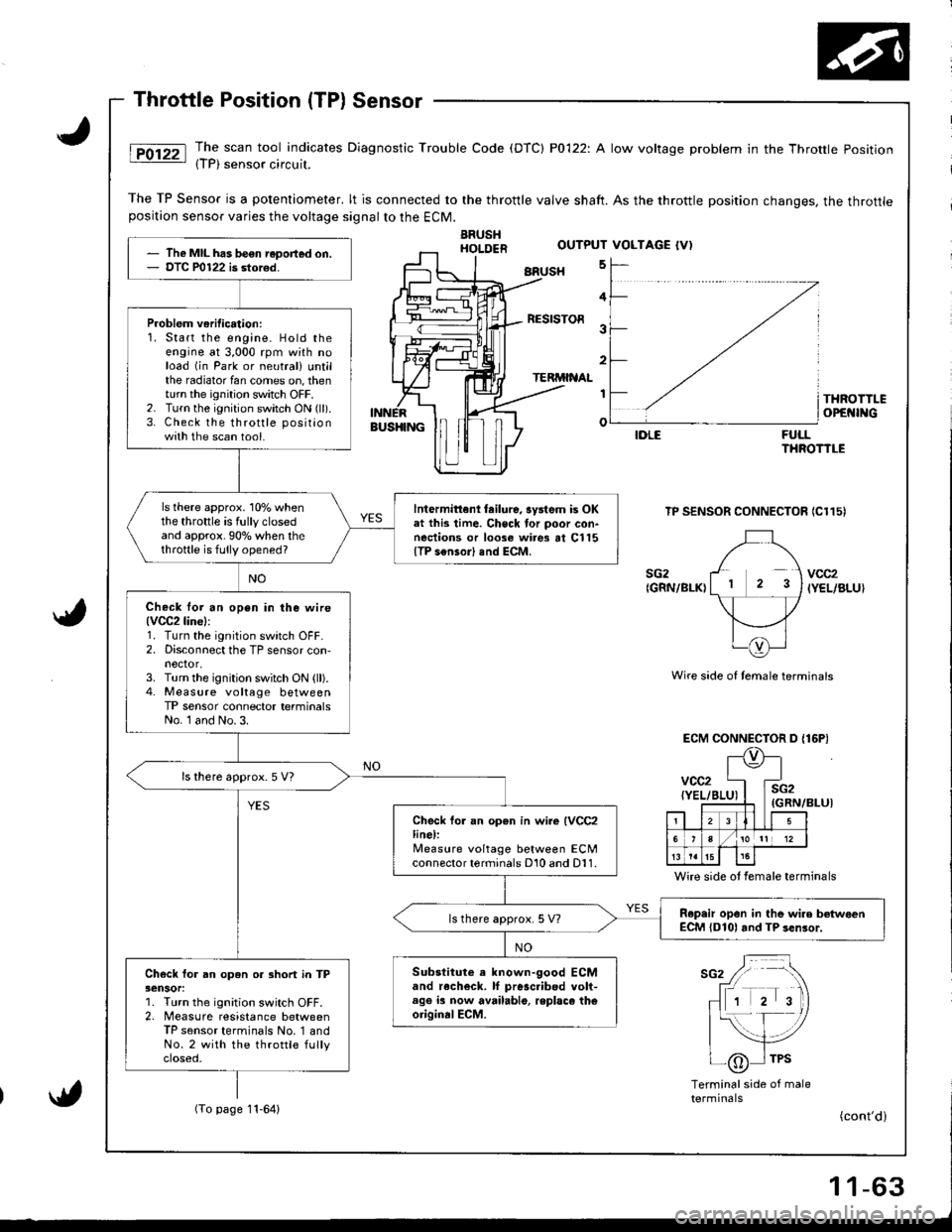
The scan tool indicates Diagnostic Trouble Code (DTC) P0122: A low voltage problem in the Throttle Position{TP) sensor circuil.
The TP Sensor is a potentiometer. lt is connected to the throttle valve shaft. As the throttle position changes, the throttleposition sensor varies the voltage signalto the ECM.
ARUSHHOI.DER
BRUSH 5
FULLTHROTTLE
TP SENSOR CONNECTOR IC115)
Wire side of temale terminals
ECM CONNECTOR D {16P)
(GRN/BLUI
Wire side ot female terminals
sG2 / -\
fr rrr r 'tr\
- 1 2 3)
|{- f- /
| _-,/tlI /6 I TPS-\j/
Terminalside of maletermrnats(To page 11-64)
The MIL has be€n reDort€d on.DTC P0122 is stor€d.
Problem veritication:1. Start the engine. Hold theengine at 3,000 rpm with noload (in Park or neutral) untilthe radiator fan comes on, thenturn the ignition switch OFF.2. Turn the ignition switch ON (ll).
3. Check the throttle positionwith the scan tool.
ls there approx. 10% whenthe throttle is fully closedand approx.90o/o when thethrottle is fully opened?
lntermittenl tailure, system is OKat this time. Check tor poor con-nections or loose wires at Cl15{TP s€nsor) end ECM.
Check lor an open in ihe wire(VCC2line):
1. Turn the ignition switch OFF.2. Disconnect the TP sensor con,nector,3. Turn the ignition switch ON (ll).4. Measure voltage betweenTP sensor connector terminalsNo. l and No. 3.
ls there approx. 5 V7
Check fo. an open in wire IVCC2line):lleasure voltage between ECMconnector terminals D10 and D11.
R.p.ir opon in tho wire betwoenECM {D101 and TP sen3or.ls there approx. 5 V?
Substitute a known-good ECMand recheck. lf pr6sc.ibed volt-age ia now available, replaco theoriginalECM.
Check for an open or 3hort in TP3ensor:1. Turn the ignition switch OFF.2. Measure resistance betweenTP sensor terminals No. '1 andNo.2 with the throttle fullyctoseo,
OUTPUT VOLTAGE {V)
4
RESISTOR3
2
TERMINAL
I
o
THROTTLEOPEI{INGBUS}IINGIDLE
sG2{GRN/BLK)vcc2IYEL/BLU}
vcc2{YEL/BI
l\e
4E
i2iRN,
. llLI5
6/101t 12
t515
(cont'd)
Page 303 of 1681
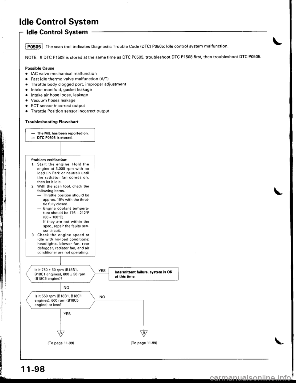
ldle Control System
ldle Control System
i P0505 | fne scan tool indicates Diagnostic Trouble Code (DTC) P0505: ldle control system malfunction,
NOTE: ll DTC Pl508 is stored at the same time as DTC P0505, troubleshoor DTC P1508 first. then troubleshoot DTC P0505.
Possible Cause
. IAC valve mechanical malfunctiorr
. Fast idle thermo valve malfunction (A"/T)
. Throttle body clogged port, improper adjustment
. Intake manifold, gasket leakage
. Intake air hose loose, leakage
a Vacuum hoses leakage
. ECT sensor incorrect output
. Throttle Position sensor incorrect output
Troubleshooting Flowchart
Problem verification:1. Start the engine. Hold theengine at 3,000 rpm wath noload 1in Park or neutral) untilthe radiator fan comes on,then let it idle.2. With the scan tool, check thefollowing items.- Throttle position should beapprox. 10% with the throttle fully closed.Engine coolant tempera-ture should be 116 212F(80 - 100'c).lf they are not within thespec., repair the faulty sensor crrcuft,3 Check the engine speed atidle with no-load conditions:headlights, blower fan, reardefogger, radiator fan, and airconditioner are not operating,
- The MIL has been reported on.- DTC P0505 is stored.
ls it 750 t 50 rpm (81881,
818C1 engines), 800 I 50 rpm(818C5 engine)?
Intermittent failur6, svstsm is OKat this tim€.
ls it 550 rpm (81881,818C1
engines), 600 rpm {818C5enginelor less?
-98
(To page 11'99)(To page 11-99)
Page 304 of 1681
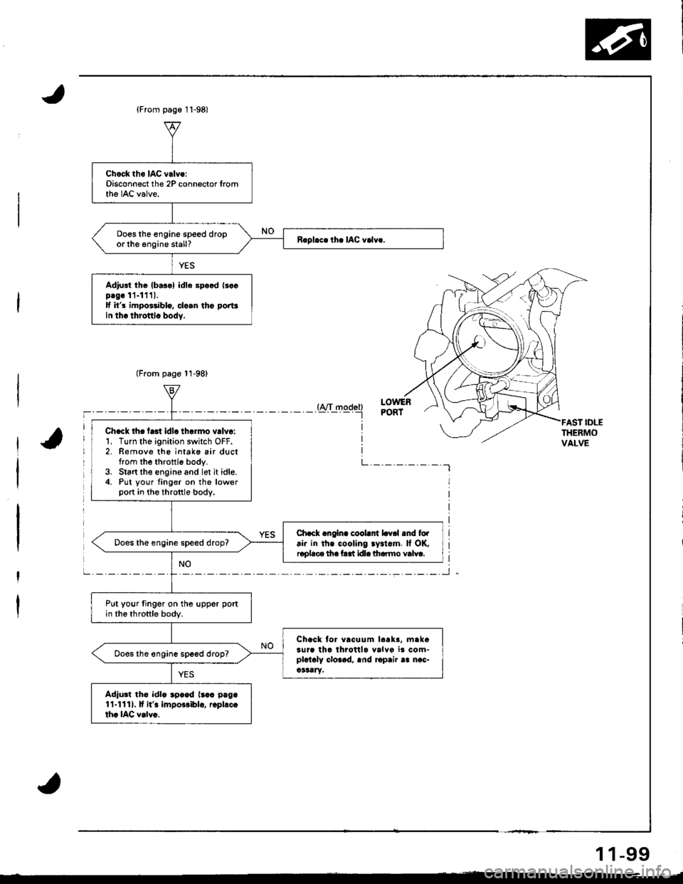
Chock th6 IAC vrlv.:Disconnect the 2P connector tromthe IAC valve.
ooes lhe engine speed droporlhe engine stall?
Adiu3t th. lb.r.l idle Bp..d lrocplgc 11-1111.lf it's impo3.iblo, clo.n tho portsin thc throftlc body.
Ch.ck th€ frtt idl. th.rmo vrlv.:1, Turn the ignition switch OFF.2. Remov€ th6 intake air ductfrom the throttle body.3. Slart the engine and let it idle.4. Put your finger on the lowerport in the thronle bodv.
Chack angina coobnt Lv.l and fo.ai. in th. cooling ry.l.m. It OK,r.place tha fatt ldla lftarmo valva.Does the engine speed drop?
Put your linger on the uppor portin the throttle body.
Chacl tor vrcuum leek3, m.lcilJa th6 throttlo valvo ir com-plotaly cloaad, rnd ropair aa nac-a3aatY,
ooes ihe engin6 speed drop?
Adiutt th€ idl. .p..d l..r p.g.11-1111. lf it'. impo3riblo, rcpl.c.thc IAC v.lvc.
{A/T model)----tLOWERPORT
L. _. _._. _. _. _.-l
IDLETHERMOVALVE
1 1-99
Page 305 of 1681
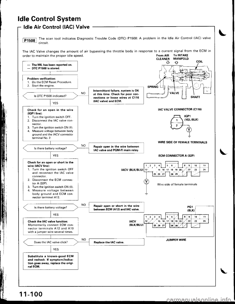
ldle Control System
Problem verification:'1. Do the ECM Feset Procedure.2. Sta rt the engine.
ldle Air Control (lAG) Valve
The scan tool indicates Diagnostic Trouble Code (DTC) P1508: A problem in the ldle Air Control (lAC) valve
crrcurt.
The IAC Valve changes the amount of air bypassing the throttle body in response to a current signal from the Eclvl in
order to maintain the proper idle speed.FTom AIB To INTAKECLEANER MANIFOLD
IAC VALVE CONNECTOR IC116}
YES
WIRE SIDE OF FEMALE TERMINALS
ECM CONNECTOR A {32PI
Check for an open or short in thewire IIACV line):1. Turn the agnition switch OFFand reconnect the IAC valve
2. Disconnect the ECM connector A (32P).
3. Turn the ignition swatch ON (ll).
4. M easu re voltage betweenbody ground and ECM connector terminal A12.
IACV {8LK/BLU}
tacv{BLK/BI-UI
The MIL has been reoorted on.OTC Pl508 is stored.
lntermittent failure, svstem is OKat this time. Check for ooor con-nections or loose wires at C116{lAC valvel and ECM.
ls DTC P1508 indicated?
Check tor an open in lhe wirellGPl line):1. Turn the ignition switch OFF.2. Disconnect the IAC valve con
3. Turn the ignition switch ON (ll).
4. Measure voltage betlveen bodyground and the IACV connectorterminalNo.2.
Repair open in the wire betweenIAC valve and PGM-FI main relav-ls there battery voltage?
Repair open or shon in the wi.ebetween ECM {A12l and lAc valve.ls there battery voltage?
Check the IAC velve function:Momentarily connect ECM con-nector terminals A12 and A10with a jumper wire several times.
Does the IAC valve click?
Substitute a known-good ECMand rocheck. lf symptom/indica-tion goes away. replace the origi-nal ECM.
','*',,'Llu.9', I l112 15 16 17 1a1o20/
l--12u1 z"-if1za-2"' . '1 .
910
t-r '21
Wire side of female terminals
JUMPER WIRE
1-100
Page 315 of 1681
ldle Control System
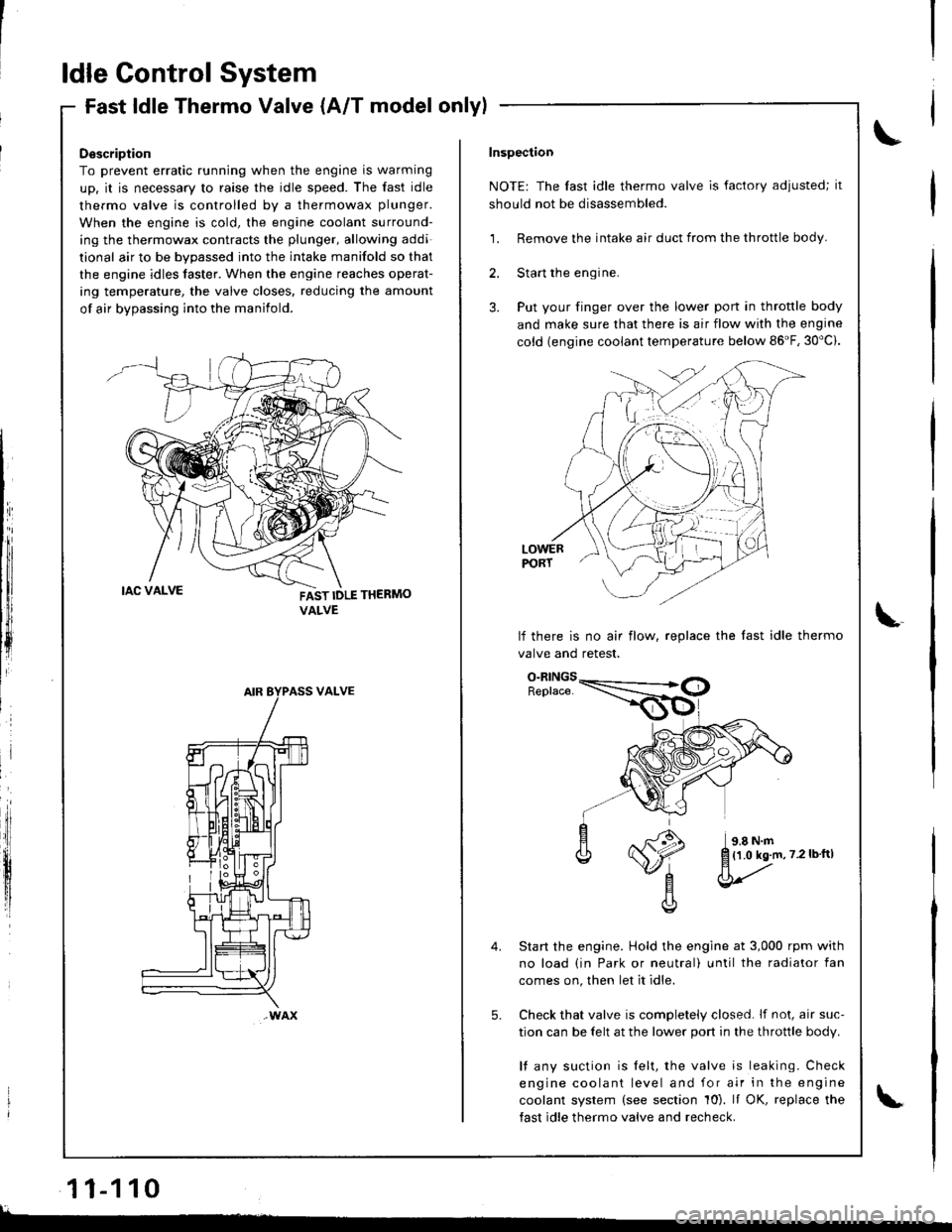
Fast ldle Thermo Valve (A/T model onlylFast ldle I nermo valve (A/ | mooel
Description
To prevent erratic running when the engine is warming
up. it is necessary to raise the idle speed. The fast idle
thermo valve is controlled by a thermowax plunger.
When the engine is cold, the engine coolant surround-
ing the thermowax contracts the plunger, allowing addi
tional air to be bvoassed into the intake manifold so that
the engine idles taster. When the engine reaches operat-
ing temperature, the valve closes. reducing the amount
of air bypassing into the manifold.
FAST IDLE THERMO
VALVE
VALVE
wAx
Inspection
NOTE: The fast idle thermo valve is factory adiusted; it
should not be disassembled.
1. Remove the intake air duct from the throttle body.
2. Start the engine.
3. Put your finger over the lower port in throttle body
and make sure that there is air flow with the engine
cold {engine coolant temperature below 86'F, 30"c).
LOWERPORT
lf there is no air flow, replace the last idle thermo
valve and retest.
Start the engine. Hold the engine at 3,000 rpm with
no load (in Park or neutral) until the radiator fan
comes on, then let it idle.
Check that valve is completely closed. lf not, air suc-
tion can be felt at the lower port in the throttle body.
l{ any suction is felt, the valve is leaking. Check
engine coolant level and for air in the engine
coolant system (see section 10). It OK, replace the
fast idle thermo valve and recheck.
5.
{1.0 kg.m,7.2lbftl
l
11-110
lL.�
Page 333 of 1681
r
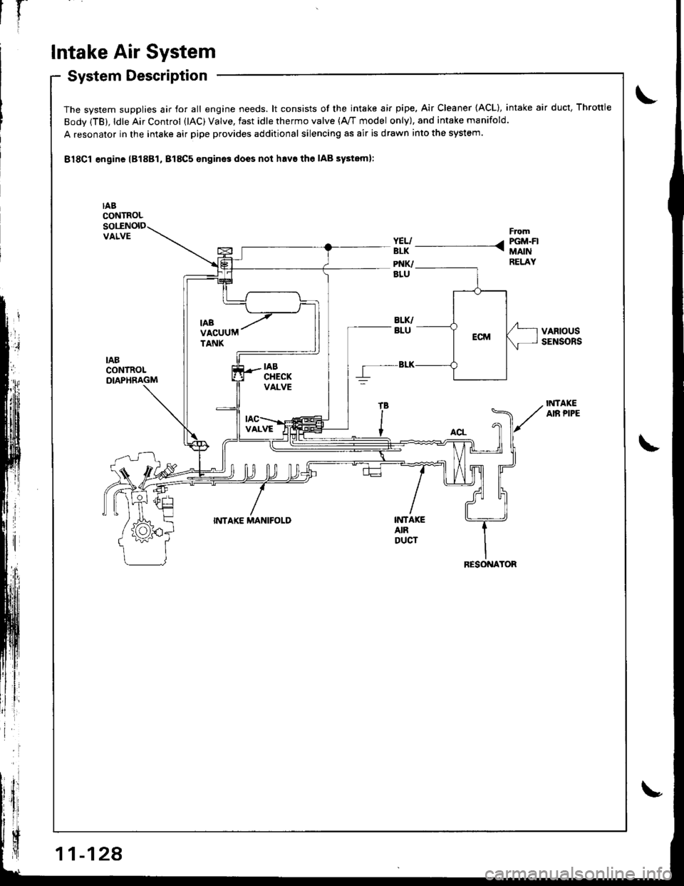
Intake Air System
System DescriptioSystem uescnpllon
The system supplies air for all engine needs. lt consists of the intake air pipe. Air Cleaner (ACL), intake air duct, Throttle
Body (TB), ldle Air Control (lAC) Valve, fast idle thermo valve (A,/T model only), and intake manifold.
A resonator in the intake air pipe provides additional silencing as air is drawn into the system.
B18Cl engine lB18Bl, B18C5 enginos does not havs the IAB systeml:
IABCONTROLsollNolDVALVE
VARIOUSSENSORS
IABCONTROLDIAPHRAGM
IiITAKEAIR PIPE
INTAKE MANIFOLDINTA|(EAIRDUCT
RESONATOR
Page 335 of 1681
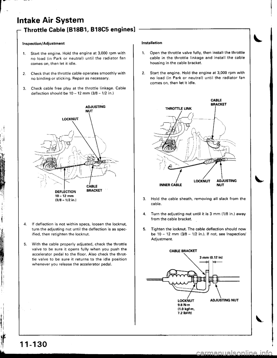
l-
Intake Air System
LOCKNUT
DEFLECTION10-12mmBIA- 112in.l
lf deflection is not within specs, loosen the locknut,
turn the adjusting nut until the deflection is as spec-
ified, then retighten the locknut.
With the cable properly adiusted, check the throttle
valve to be sure it opens fully when you push the
accelerator pedal to the floor. Also check the throt-
tle valve to be sure it returns to the idle position
whenever you release the accelerator pedal.
Throttle Cable IB18B1, 818C5 engines]
Inspection/Adiustment
1. Start the engine. Hold the engine at 3,000 rpm wirh
no load (in Park or neutral) until the radiator tan
comes on, then let it idle.
2. Check that the throttle cable operates smoothly wilh
no binding or sticking. Repair as necessary.
3. Check cable free play at the throttle linkage. Cable
deflection should be 10 - 12 mm (3/8 - 'l12 in.l
ADJUSTINGNUT
t
il
qr
ll1 1-130
!!
TING NUT
\lnstallation
1. Open the throttle valve fully, then install the throttle
cable in the throttle linkage and install the cable
housing in the cable bracket.
2. Start the engine. Hold the engine at 3,000 rpm with
no load (in Park or neutral) until the radiator fan
comes on, then let it idle.
INNER CABLE
Hold the cable sheath, removing all slack from the
caote.
Turn the adjusting nut until it is 3 mm {1/8 jn.) away
from the cable bracket.
Tighten the locknut, The cable deflection should now
be 10 - '12 mm (3/8 - 'll2 in.). lf not, see Inspection/
Adjustment.
3 mm 10.12 inl
u
4.
AD
\
JUSLOCKNUT9.8 N.m(1.0 kgt.m,7,2lbl.ttl
CABI.E
CABI,E BMCKET
Page 336 of 1681
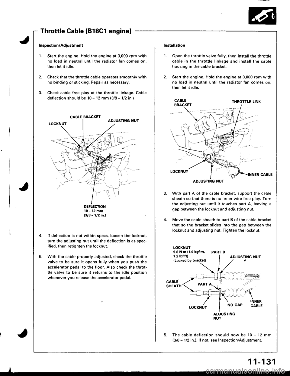
't.
Inspsction/Adiustmsnt
Stan the engine. Hold the engine at 3,000 rpm with
no load in neutral until the radiator fan comes on,
then let it idle.
Check that the throttle cable operates smoothly with
no binding or sticking. Repair as necessary.
Check cable free play at the throttle linkage. Cable
deflection should be 10 - 12 mm (3/8 - 1/2 in.)
DEFTECTION10- 12 mmBIA-112in.l
lf deflection is not within specs, loosen the iocknut.
turn the adjusting nut until the deflection is as spec-
ified, then retighten the locknut.
With the cable properly adjusted, check the throttle
valve to be sure it opens fully when you push the
accelerator pedal to the floor. Also check the throt-
tle valve to be sure it returns to the idle position
whenever you release the accelerator pedal.
CABLE BBACKET
lnstallation
Open the throttle valve fully, then install the throttle
cable in the throttle linkage and install the cable
housing in the cable bracket.
Stan the engine. Hold the engine at 3,000 rpm with
no load in neutral until the radiator fan comes on,
then let it idle.
l.
3.
5.
CABLEBRACKETTHROTTLE LINK
ADJUSTING NUT
With part A of the cable bracket. support the cable
sheath so that there is no inner wire tree plav. Turn
the adjusting nut until it touches part A, leaving a
gap between the locknut and adjusting nut.
Move the cable sheath to oart B of the cable bracket
that so the bracket slides into the gap between the
locknut and adjusting nut. Tighten the locknut.
LOCKNUT9.8 N.m 11.0 kgf.m, PART 87.2lbf.frl(Lockod by bracketl
CABLESHEATH
NO GAPINNERCABLE
ADJUSTINGNUT
The cable deflection should now be 10 - 12 mm(318 - 112 in.l. lf not. see Inspection/Adjustment.
ADJUSTING NUT
1 1-131