Compressor HONDA INTEGRA 1998 4.G Repair Manual
[x] Cancel search | Manufacturer: HONDA, Model Year: 1998, Model line: INTEGRA, Model: HONDA INTEGRA 1998 4.GPages: 1681, PDF Size: 54.22 MB
Page 1390 of 1681
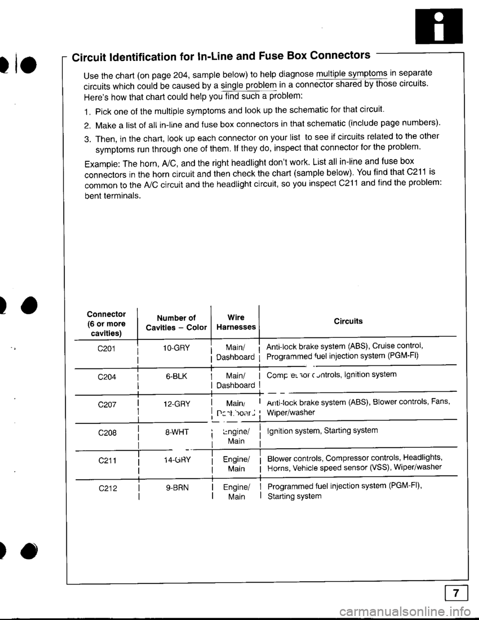
Circuit ldentification for In'Line and Fuse Box Connectors
tuse the chart (on page 204, sample below) to help diagnose multiple symptoms in separate
circuits which could be caused by a single problem in a connect,oishared by those circuits'
Here's how that chart could help you find such a problem:
1. Pick one of the multiple symptoms and look up the schematic for that circuit'
2. Make a list of all in-lrne and fuse box connectors in that schematic (include page numbers).
3. Then, in the chart, look up each connector on your list to see if circuits related to the other
symptoms run through one of them. lf they do, inspect that connector for the problem.
Example: The horn, A,/C, and the right headlight don't work. List all in-line and fuse box
connectors in the horn circuit and then check the chart (sample below). You find that C211 is
common to the A,/C circuit and the headlight circuit, so you inspect c211 and find the problem:
bent terminals.
)Connector
(6 or more
cavities)
Numbel of
Cavities - Color
1O-GRY
I 12-GRY
I
Wire
Harnesses
I Main/ | ComP er 'ror c.ntrols,
I Dashboard I
Circuits
Ant!lock brake system (ABS), Cruise control,
Programmed {uel injection system (PGM-FD
!ngrnei
lvlain
lgnition system
Antilock brake system (ABS), BIower controls, Fans,
Wiper/washer
lgnition system, Starting system
Blower controls, Compressor controls, Headlights'
Horns, Vehicle speed sensor (VSS), Wiper/washer
Programmed fuel injection system (PGM-Fl)'
Starting system
Engine/ |Main I
)
Page 1401 of 1681
Fuse
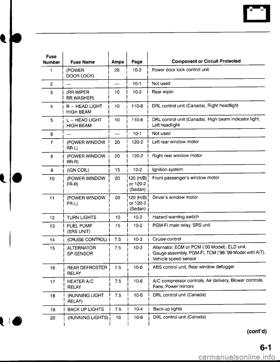
NumberFuse NameAmpsPagecomponent or circuit Protected
(POWER
DOOR LOCK)
(RR WIPER
RR WASHER)
R _ HEAD LIGHT
HIGH BEAM
j 1o-2Power door lock control unit
10-2 | Rear wiper
I
tto-e i onLcontrol unit (Canada), Right headlight
L _ HEAD LIGHT
HIGH BEAM
(POWER WINDOW
RR-L)
i 1 10-8i DRL control unit (Canada), High beam indicator light,
i Left headlight
1 0-1Not used
| 1zo-z
I
I Left rear window motor
| (lGN colL)| 15
(POWER WINDOW
FR-R)
(POWEB WINDOW
FR-L)
I Right rear window molor
I
Front passenger's window motol
Driver's window motor
| 120-2
i120 (H/B)
iot 120-2
l(Sedan)
i120 (H/B)
l0:120 ?
IJ13
TURN LIGHTS
FUEL PUMP
(SRS UNIT)
(Sedan)
'lo-2Hazard warning switch
1O-2 | PGM-FI main relay, SRS unit
I
14I (cRUlsE coNTRoL) | 7.510-3 | Cruise control
ALTERNATOR
SP SENSOR
7.510-3Alternator, ECM or PCM ('00 Model), ELD unit,
Gauge assembly, PGM-Fl, TCM ('98-'99 Modelwith A/f),
Vehicle speed sensor
i REAR DEFBOSTER ii RELAY i
10-6i ABS control unit, Rear window defogger
I HEATER A/C
: RELAY
fuC compressor controls, Air delivery, Blower controls,
Fans. Power mirrors
I tnururutruc ucxr I z.s
I otrt av I
I DRL control unit (Canada)10-6
I BACK UP LIGHTS | 7.s | 10-4 I Back-up lights
t
(RUNNTNG LTGHTS) ii DRL control unit (Canada)
(cont'd)
19
6-1
Page 1403 of 1681
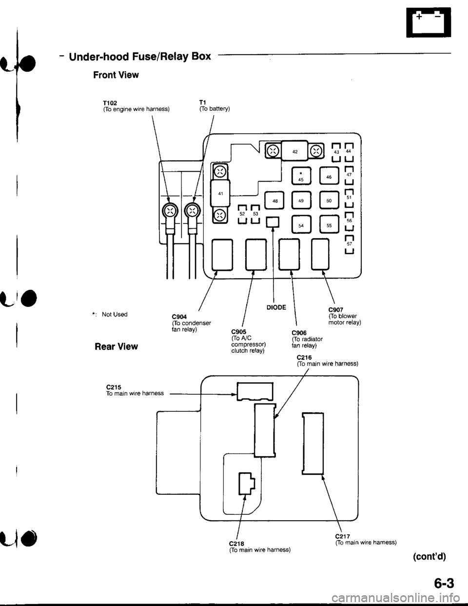
- Under-hood Fuse/Relay Box
Front View
T102Oo engine wire harness)
*: Not Used
Rear View
c2l5To main wire harness
T1[ro battery)
c905[ro F/Ccompressor)clutch relay)
c2t8[fo main wire harness)Oo main
(cont'd)
D3
tr
tr
[J
r'1
IJ
r-t
IJ
r'151
LI
r-156
IJ
r"l57
LI
Llowire harness)
6-3
Page 1404 of 1681
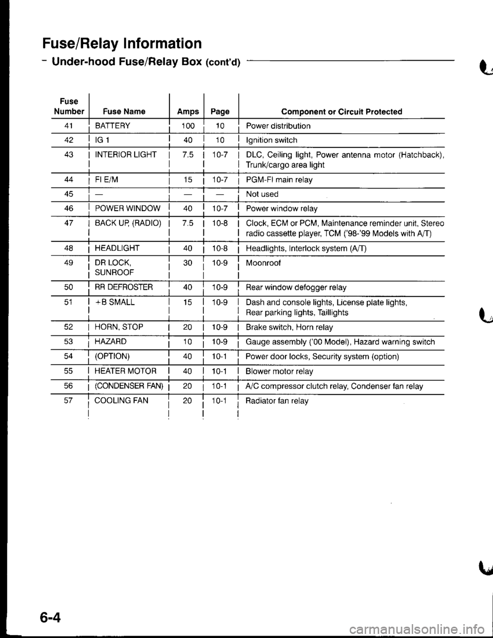
Fuse/Relay I nformation
- Under-hood Fuse/Relay Box (cont'd)
Fuse
NumberFuse NameAmpsPage
BATTERY
I INTERIOR LIGHT
I
1 7.5 110-7 I
I
Component or Circuil Protected
Power distribution
lgnition switch
DLC, Ceiling light, Power antenna motor (Hatchback),
Trunk/cargo area light
47
I Fl E/lvl
POWER WINDOW
I BACK UP (RADTO)
I
15 | 1 0-7 I PGM-FI main relay
Not used
Power window relay
Clock, ECM or PCM, Maintenance reminder unit, Stereo
radio cassette player, TCM ('98-'99 Models with A'/T)
7.5 |10-8
I HEADLIGHT| 40 | 10-8 | Headlights, Interlock system (A/T)
49i DR LOCK,
i suNRooF
10-9 i Moonroof
I
I RR DEFROSTER
+ B SMALL
I Rear window detogger relay
I Dash and console lights, License plate lights,
I Rear parking lights, Taillights
I HORN, STOP
i HAZARD
10-9 | Brake switch, Horn relay
i Gauge assembly ('00 Model), Hazard warning switch
40 | to t I Power door locks, Security system (option)
I HEATER MOTOR II t 0-1I Blower motor relay
20 I 10-1 ; A,/C compressor clutch relay, Condenser fan relay
i Radiator fan relay1 0-1
6-4
Page 1414 of 1681
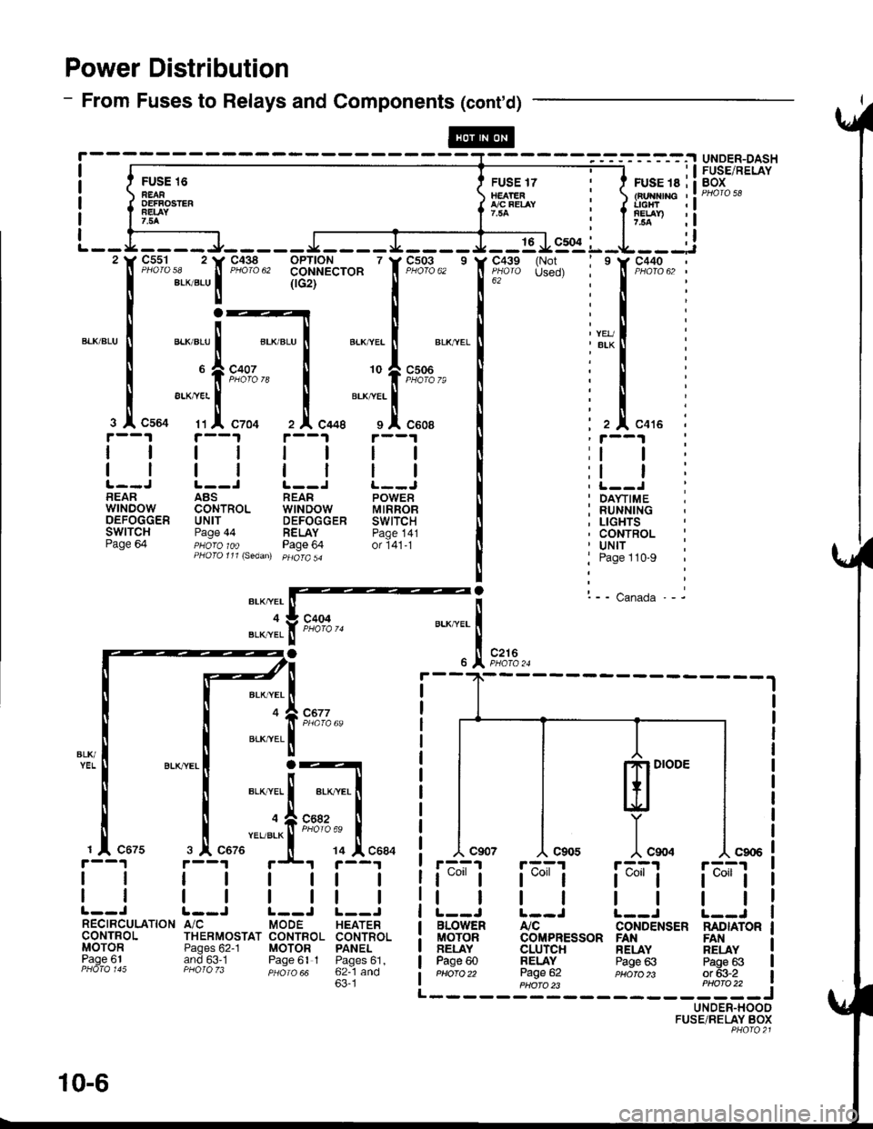
Power Distribution
- From Fuses to Relays and Components (cont'd)
FU'E 16 Err*rrilnEAR tEArEn : tFurflnc ,:oEFFosrER { flfo"t-t i { l'rtTr :!7.5A I : I 7.5a ,l
ffi-.^,; l:lL - - L __ _ _ J_ _ _ _ _ J __ _ _ I _ __ _ J _ _ 16 J9:91 L _L _ _ _:i'tr F"?%,, 'tr'F"Xlg", 331'$A"'o* ' f F;03,, ' lf ;'"11'" {H!, i ' f t"X13,, :
I eLxaLul (rcrt'--'-' I 16z
""""'
i I :
r:_lrl:
":1",-:ri;:t
ll".",:{.tFz'€; I lll".,. i
rt i'--t rt i--t i ;i--i i
t__J t__l r__J !._-J ! i t__.t iBEAR ABS REAR POWER II ' DA\.TIME ;wrNDow coNTRoL wtNDow MtRRoB I : RUNNTNGoEFoccER uNrr DEFoccER swtrcH It ; LtcHTsSWITCH Page 44 RELAY paoe 141 I , CONTROL :Page 64 pHoro 1oo Page 64 or i41-t [ ' Uttf :PHoro111\sedan) pHoro5a
! j Page 110-9
|
! l-- canada.- it*rarffi'
"JI.f t*', u..^""1
-.
)t .,1, r*,.
BLK,YEL
BLK,YEL
ml'"
]"*.r-A?1
t*"1
tl
BLOWENMOTORBELAYPage 60Pttofo 22
rF^;'l
t*l
tl
Atc
UNDER-DASHFUSE/RELAYBOX
c677
L--J |.--J L--JA/C MODE HEATERTHERMOSTAT CONTBOL CONTROI.Pages 62-1 MOTOR PANELand 63.1 Paqe 61 I Paoes61.PHO|O zJ psiro aa 62--1 and63'1
r'--?1 r;^;'r
t*"lt*"1
tttlL--J L--JCONDENSER NADIATORCOMPRESSOR FANCLUrcHBELAYPage 62
RELAYPage 63
FANRELAYPags 63or 63-2PHA|O )3 PHO|O 22 i------JUNDER-HOODFUSE/RELAY BOXPHQ|O2l
@
10-6
Page 1450 of 1681
UNDER.HOODFUSE/RELAYBOXl'-J-'uC-*---l
Lfl:::j
*".^;[
k;i*,,
! oao" to'z
*"''"T.1,
"oou
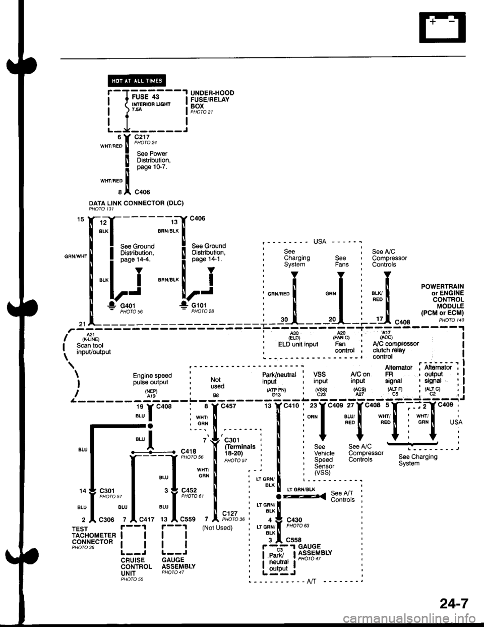
DATA LINK CONNECTOR (DLC}
See L/CCompressorControls
"X-*T-__-;"E::"
Il.Ll--- ;"--.'-[*"
| ! :ne,t*c il ;*,f,n*.1 i ;;"
-' usA ---
"-""'l
"*i,:Y' """"..ij1"
i"""".tlf*' "".7
u,i"""'*.16J
,]:f J
Jcror
I Scan tool : ELD unit inputI i.^'tr/^,fh,'t . CollllolI ,r,PuvvurrruL\L- - -r*i**"i
I *. ry'con An€mator : i.ff*o'I iinput ; input inpd signal : sEnal : I
- - i'ril - :- g - - iE- - i:i - - l:i - -,, i
, I i;:l*'#[""*ifitf{*,u
rals . n bee rccwu E---,
. i I :X3:'""1" 3:lllJij*'see,ciarsins; I :55;;, system
n ; ryss)
i'Tlli '----------r
; :g< 9:"lI '
i r"r cnr, | *"""- :, BLK T: 4 Y 943! |: Lr GFN/ I PHoro 63
i i*l "uu,:-.i.I GAUGE; leairi, llJ_s*l4BLY
i it:l*i' r-"'"" :, L=":Jl----------AlT -
'
Engine speed l"-----'--"
i ;,rs;,ipi,i- i l$.
/q:9'B€L------------l-
lr.r"oo. : 8 rc4s7
Jl :"-r!
".,1 .-L-.... ".
''{'r*,"',
il*'H;{l !-,
TFsr |. --1 f --1 (Not Used) ;iadiror,reren | | | | |
F8ilil5"'o"t | | | :
L--J L--JCRUISE GAUGECONTROL ASSEMBLYuNlT PHOfO 47PHOTA rr
c457
24-7
36
Page 1473 of 1681
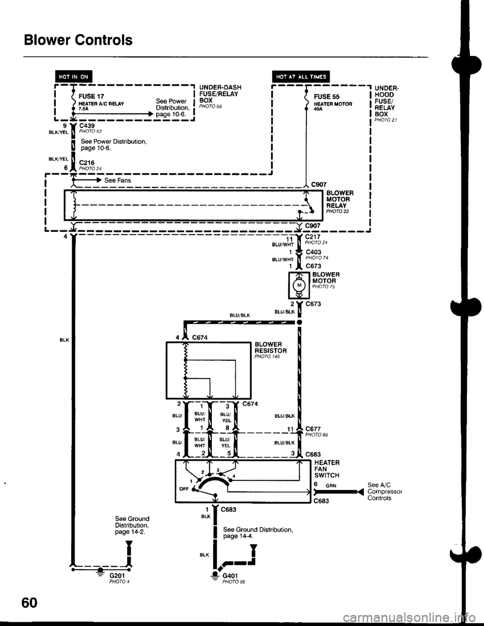
Blower Controls
FUSE 17HE TEn ,'/C nELAY7.5ASee PowetDistribution,page 10-6.
UNDER.DASHFUSE/RELAYBOX
---G;;-'
/ HEATER I'OTOR
l*^
I
I
I
---1"*'
UNOER.HOODFUSE/RELAYBOXL - y' - - - - - - - -:: - - J9 Y C439.KryEL ! P/roro 62BLK|/EL ll PHOIO 62
BLOVYERMOTORFELAYPHOTO 22
9s_____i
".u-", f, i'ii'o '.
1 l c6z3
Hfib#i
".,,".?[ "ut'
- -i;a' c217BLU 1,vi{r
J
PHoro '�u
C677PHOTO 69:rI#
c683
HEATERFANswtTcH
6 cnr
)-<
See A/CCompressorControls
1BLKc683
See Ground Distribution,page 14-4.
I
J
See GroundOistribution,page 14-2.
: G201
60
Page 1479 of 1681
A/C Gompressor Controls (conrd)
- How the Circuit Works
Battery voltage is supplied through fuse 56 to the
A,/C compressor clutch relay contacts at all times.
With the ignition switch in ON (ll), voltage is applied
to the coil of the A,/C compressor clutch relay
through fuse 17. When you push the A,/C switch
ON, and the heater fan switch is in posation 1, 2, 3,
or 4, a "ground" input is provided to the engine or
powertrain control module (ECM or PCM) through
the A,/C thermostat and the A,/C pressure switch.
The A,/C compressor clutch relay is grounded by the
engine or powertrain control module (ECM or PCM).
When energized, the A,/C compressor clutch relay
allows battery voltage to turn on the A,/C
comDressor clutch,
The A,/C ON indicator light comes on when the A"/C
system is requested.
A,/C Thermostat
The A,/C thermostat is located on the evaoorator
housing. The AJC thermostat turns off the A,/C
compressor clutch if the temperature at the
evaporator goes below 3'C (37'F). This prevents
condensation from freezing on the evaporator fins
and blocking the air delivery into the passenger
compartment. The blower motor will keep running
when the sensor lurns off the compressor.
A,/C Pressure Switch
The A,/C pressure switch is located in the condenser
outlet line where refrigerant is in a high
temperature/high pressure liquid state. The switch
will sense abnormally high or low pressure, and
open the circuit. This removes ground, and the
compressor will stop running.
Refer to the Service Manual (Section 22,
Air Conditioning) for specific tests or
troubleshooting procedures.
62-2
Page 1483 of 1681
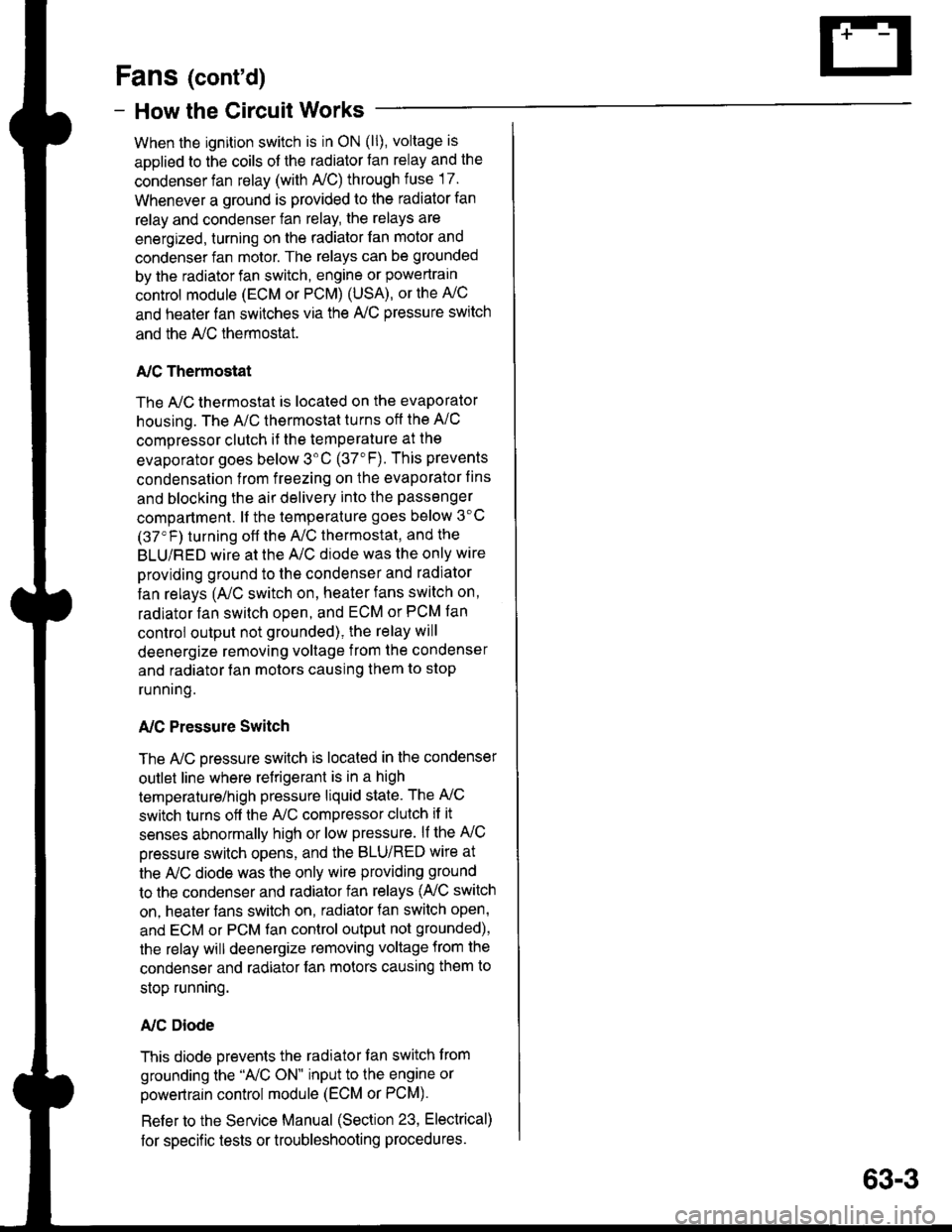
Fans (cont'd)
- How the Gircuit Works
When the ignition switch is in ON (ll), voltage is
applied to the coils of the radiator fan relay and the
condenser fan relay (with A,/C) through fuse 17.
Whenever a ground is provided to the radiator fan
relay and condenser fan relay, the relays are
energized, turning on the radiator fan motor and
condenser fan motor. The relays can be grounded
by the radiator fan switch, engine or powertrain
control module (ECM or PCM) (USA), or the A,/C
and heater lan switches via the A'lC pressure switch
and the A,/C lhermostat.
A,/C Thermostat
The A,/C thermostat is located on the evaporator
housing. The A/C thermostat turns oft the A/C
compressor clutch it the temperature at the
evaporator goes below 3'C (37"F). This prevents
condensalion from freezing on the evaporator fins
and blocking the air delivery into the passenger
compartment. lt the temperature goes below 3'C
(37'F) turning off the A"/C thermostat, and the
BLU/RED wire at the A,/C diode was the only wire
providing ground to the condenser and radiator
fan relays (A,/C switch on, heater fans switch on,
radiator fan switch open, and ECM or PCM fan
controi output not grounded), the relay will
deenergize removing voltage from the condenser
and radiator fan motors causing them to stop
running.
A,/C Pressure Switch
The AJC oressure switch is located in the condenser
outlet line where refrigerant is in a high
temperature/high pressure liquid state. The A,/C
switch turns off the A,/C compressor clutch if it
senses abnormally high or low pressure. lf the A'lC
pressure switch opens, and the BLU/RED wire at
the A/C diode was the only wire providing ground
to the condenser and radiator fan relays (L/C switch
on, heater fans switch on, radiator lan switch open'
and ECM or PCM fan control output not grounded),
the relay will deenergize removing voltage from the
condenser and radiator fan motors causing them to
stop running.
A./C Diode
This diode orevents the radiator fan switch f rom
grounding the "A'lC ON" input to the engine or
powertrain control module (ECM or PCM).
Refer to the Service Manual (Section 23, Electrical)
for specific tests or troubleshooting procedures.
63-3
Page 1596 of 1681
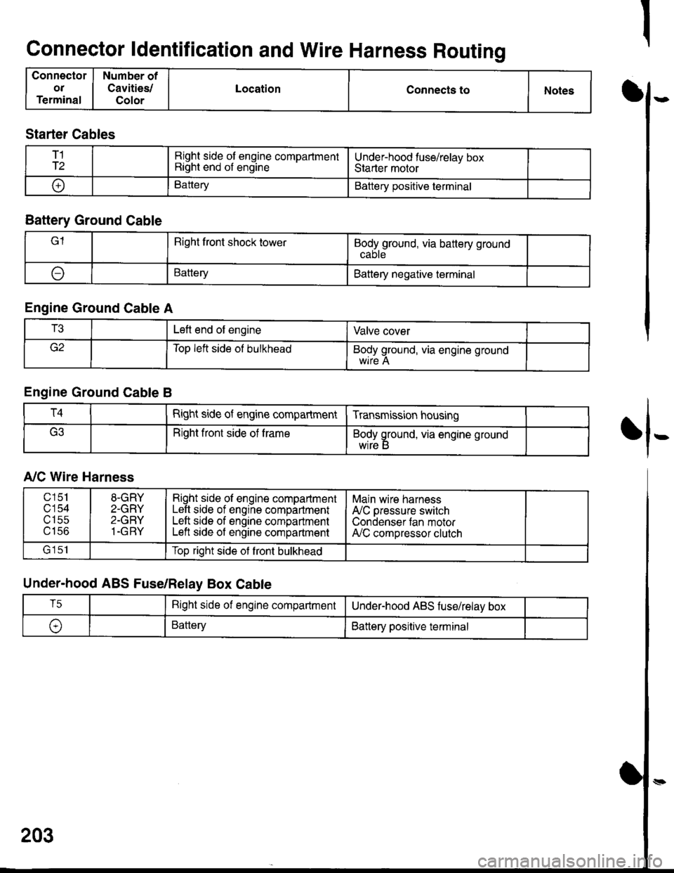
Connector ldentification and Wire Harness Routing
Connector
OT
Terminal
Number of
Cavities/
Color
LocationConnecls toNotesI
fl-
Starter Cables
T1
T2Right side of engine compartmentRight end of engineUnder-hood fuse/relav boxStarter motor
oBatteryBattery positive terminal
Battery Ground Cable
lRight front shock towerBodyground, via battery ground
ABatteryBattery negative terminal
Engine Ground Cable A
T3Left end of engineValve cover
Top left side ol bulkheadBody ground, via engine ground
Engine Ground Cable B
T4Right side of engine compartmentTransmission housing
Right front side of trameBody ground, via engine ground
wrre b
A,/C Wire Harness
Under-hood ABS Fuse/Relay Box Cable
203
c151
c'154utSc
u tco
8-GRY
2-GRY
2-GRY
1-GRY
Right side ol engine compartmentLeft side of engine compartmentLeft srde of engine compartmentLeft side of engine compartment
Main wire harness
A'lC pressure switch
Condenser tan motorA,/C compressor clutch
lrlclTop right side ot front bulkhead
T5Right side of engine compartmentUnderhood ABS fuse/relav box
\,BatteryBattery positive terminal