Compressor HONDA INTEGRA 1998 4.G User Guide
[x] Cancel search | Manufacturer: HONDA, Model Year: 1998, Model line: INTEGRA, Model: HONDA INTEGRA 1998 4.GPages: 1681, PDF Size: 54.22 MB
Page 253 of 1681
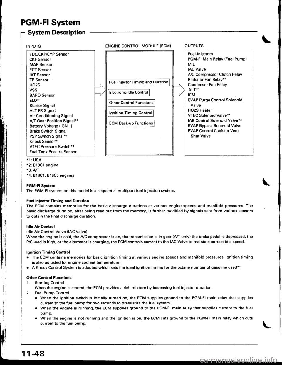
PGM-FI System
System Description
ENGINE CONTROL MODULE (ECM)OUTPUTS
*1: USA*2: 818C1 engine*3: A,/T*4: 818C1, 818C5 engines
PGM-FI Sy3tem
The PGM-Fl system on this model is a sequential multiport fuel injection system.
Fuel lniector Timing and Duration
The ECM contains memories for the basic discharge durations at various engine speeds and manifold pressures. The
basic discharge duration, after being read out from the memory. is further modified by signals sent from various sensors
to obtain the final discharge duration.
ldle Air Control
ldle Ai. Control Valve (lAC Valve)
When the engine is cold, the Ay'C compressor is on. the transmission is in gear (Ay'T only)the brake pedal is depressed, the
P/S load is high, or the alternator is charging, the ECM controls current to the IAC Valve to maintain correct idle speed.
lgnition Timing Control
. The ECM contains memories for basic ignition timing atvarious engine speeds and manifold pressures, lgnitiontiming
is also adjusted for engine coolant temperature.
. AKnockControl System isadoptedwhich sets the ideal ignition timing for the octane n um ber of gasoline used*r,
Other Control Functions
L Starting Control
When the engine is started, the ECM provides a rich mi{ure by increasing fuel injector duration.
2. Fuel PumD Control
. When the ignition switch is initially turned on, the ECM supplies ground to the PGM-FI main relay that supplies
current to the fuel pump for two seconds to pressurize the fuel system.
. When the engine is running, the ECM supplies ground to the PGM-FI main relay that supplies current to the fuel
DUmO.
. When the engine is not running and the ignition is on. the ECM cuts ground to the PGM-FI main relay which cuts
current to the fuel oumo.
INPUTS
TDc/CKP/CYP Sensor
CKF Sensor
MAP Sensor
ECT Sensor
IAT Sensor
TP Sensor
HO2S
VSS
BARO Sensor
ELD*1
Starter Signal
ALT FR Signal
Air Conditioning Signal
A,/T Gear Position Signal*3
Battery Voltage (lGN.1)
Brake Switch Signal
PSP Switch Signal*'�
Knock Sensor*1
VTEC Pressure Switch*4
Fuel Tank Prssure Sensor
Fuel InjectorTiming and Duration
Electronic ldle Control
Other Control Functions
lgnition Timing Control
ECM Back-uD Functions
Fuel-lnjectors
PGM-Fl Main Relay (Fuel Pump)
MIL
IAC Valve
A,/C Compressor Clutch Relay
Radiator Fan Belay*1
Condenser Fan Relay
ALT*1
rcM
EVAP Purge Control Solenoid
Valve
H02S Heater
VTEC Solenoid Valve*'
IAB Control Solenoid Valve*,
EVAP Bypass Solenoid Valve
EVAP Control Canister Vent
Shut Valve
11-48
Page 254 of 1681
3.Fuel Cut-off Control
. Du ring dece leration with the th rottle va lve closed, cu rrent to the fuel injectors is cutoffto improvefuel economyat
speeds over following rpm:. B'1881 engine: 970 rpm {Canada model: 1.050 rpm). B18C1 engine:970 rpm {Canada model: 1.050 rpm). 818C5 engine: 1,300 rpm (Canada model: 1,400 rpm)
. Fuel cut-off action also takes place when engine speed exceeds 7,000 rpm (B'1881 engine), 8.100 rpm (818C1
engine) or 8,600 rpm (818C5 engine), regardless ol the position of the thronle valve, to protect the engine from
over-revving.
A,,/C ComDressor Clutch Relav
When the ECM receives a demand for cooling from the air conditioning system, it delays the compressor from being
energized, and enriches the mixture to assure smooth transition to the A,/C mode.
Evaporative Emission (EVAP) Purge Control Solenoid Valve
When the engine coolanl temperature is above '154'F (68'C) and the air conditioner on. the ECM controls the EVAPpurge control solenoid valve which controls vacuum to the EVAP purge control canister.
Intake Air Eypass (lAB) Control Solenoid Valve*a
When the engine rpm is below 5,750 rpm, rhe IAB control solenoid valve is activated by a signal from the ECM, intake
air flows through the long intake path, then high torque is delivered. At speeds higher than 5,750 rpm, the solenoidvalve is deactivated by the ECM, and intake air flows through the short intake path in order to reduce the resistance in
airflow.
Sell-diagnosis Function lMalfunction Indicator Lamp {MlL)lWhen an abnormality occurs in a signal from a sensor, the ECM supplies ground for the MIL and stores the code in
erasable memory. When the ignition is initially turned on, the ECM supplies ground for the N4lL tor two seconds to
check the MIL bulb condition.
Two Driving Cycle Detection Method
To prevent false indications, the Two Driving Cycle Detection Method is used for the HO2S, fuel metering-related, idle
control system, ECT sensor, TWC and EVAP control system and other self-diagnostic functions, When an abnormality
occurs, the ECM stores it in its memory. When the same abnormality recurs after the ignition switch is turned OFFand ON (ll)again, the ECM informs the driver by lighting the MlL.
However, to ease troubleshooting, this function is cancelled when you shon the service check connector. The MIL will
then blink immediately when an abnormality occurs.
4.
5.
6.
3.
4.
ECM Fail-safe/8ack.up F0nctions
1. Fail-sate Function
When an abnormality occurs in a signal from a sensor, the ECM ignores that signal and assumes a pre-programmed
value for that sensor that allows the enqine to continue to run.
2. Back-uo Function
When an abnormality occurs in the ECM itself, the fuel injectors are controlled by a back-up circuit independent of the
system in order to permit minimal driving.
11-49
Page 308 of 1681
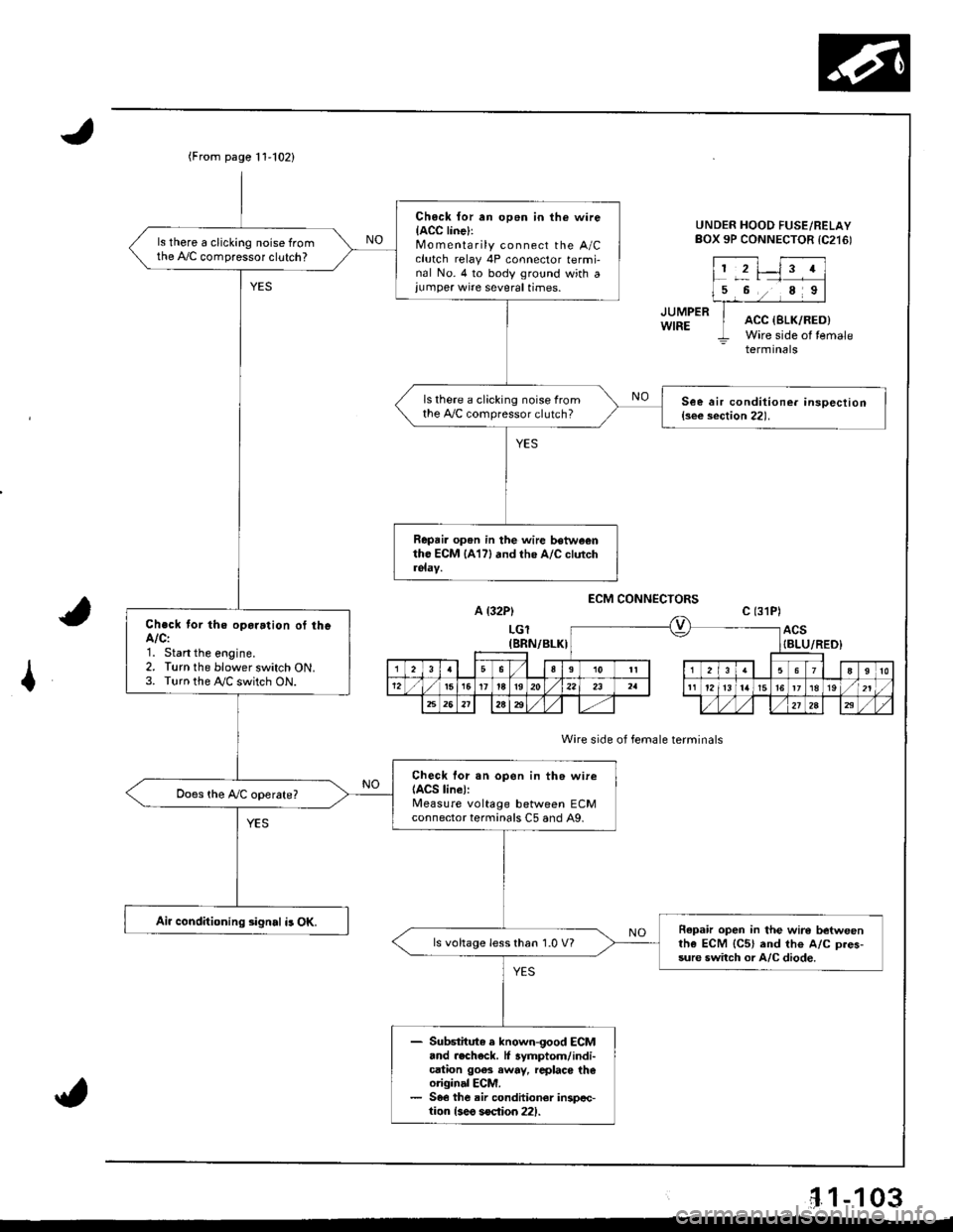
(From page t 1'102)
Ch6ck {or an op6n in the wireIACC linel:Mo m enta rily connect the A/Cclutch relay 4P connector termi-nal No. 4 to body ground with a,umper wire several times.
ls there a clicking noise fromthe A,/C compressor clutch?
ls there a clicking noise fromthe 4,./C compressor clutch?See air conditione. insoection{s€e section 22).
Repai. op6n in the wire betwe€ntho ECM lA17l and the A/C clutch
Check tor the oparation of theA/C:1. Start the eogine.2. Turn the blower switch ON.3. Turn the !y'C switch ON.
Check lor sn open in th6 wireIACS line):Measure voltage between ECMconnector terminals C5 and A9,
Air conditioning signal i3 OK.Repafu open in the wire betweenthe ECM {C5} and th€ A/C D.es-sure switch or A/C diode.
ls voltage less than 1.0 V?
- Substitute e known-good ECM.nd .echeck. lf 3ymptom/indi-cation goes away, rcplaco th€original ECM.- 56€ the air conditionor inspcc-tion {3eo soction 221.
UNDER HOOD FUSE/RELAYBOX 9P CONNECTOR tC216)
JUMPERWIREACC {SLK/RED)Wire side of temale- terminals
A {32P)
LGl(BRN/BLKI
ECM CONNECTORS
Wire side of female terminals
c (31P)
ACS{BLU/RED}
I
'1.1-103
Page 419 of 1681
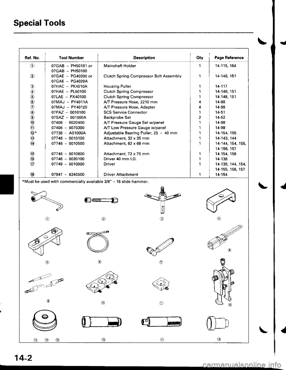
Special Tools
t
{
{
I
\-
\
14-2
Ref. No. I Tool NumberDescriptionOty I Psge Reference
o
o
o
lol
o
@
o
@
@
@-
@
@
@
@
@
@
07GAB - PH50l01 or
07GAB - PH50100
07GAE - PG40200 or
OTGAE _ PG4O2OA
07HAC - PK4010A
07HAE - P150100
07LAE - PX40100
OTMAJ - PY4O11A
07MAJ - PY40120
07PAZ - 0010100
07sAz - 001000A
07406 - 0020400
07406 - 0070300
07736 - A01000A
07746 - 0010100
07746 - 0010500
07746 - 0010600
07746 - 0030100
07749 - 0010000
07947 - 6340500
Mainshaft Holder
Clutch Spring Compressor Bolt Assembly
Housing Puller
Clutch Spring Compressor
Clutch Spring Compressor
,VT Pressure Hose, 2210 mm
A/T Pressure Hose, Adapter
SCS Service Connector
Backprobe Set
A,/T Pressure Gauge Set dpanel
Ay'T Low Pressure Gauge w/panel
Adjustable Bearing Puller,25 - 40 mm
Attachment, 32 x 35 mm
Attachment, 62 x 68 mm
Attachment, 72 x 75 mm
Drive. 40 mm l.D.
Driver
Driver Attachment
1
1
I
I
1
1
1'l
'l
'11-115. 164
14-148, 151
14-117
14-148, 151
14-148, 151'14-98
14-98
14-51
14-52
l4-98
14-98
l4-154, 155
14-143,'t44
14-144. 154, 155,
14-156, 157
14-154, 155
14-138
14-134, 144, 't54,
14-155, 156, 157
14-154
*Must be used with commerciallv available 3/8" - 16 slide hammer.
Edr$ri"-E
arl
@o
@@@c0
Page 466 of 1681
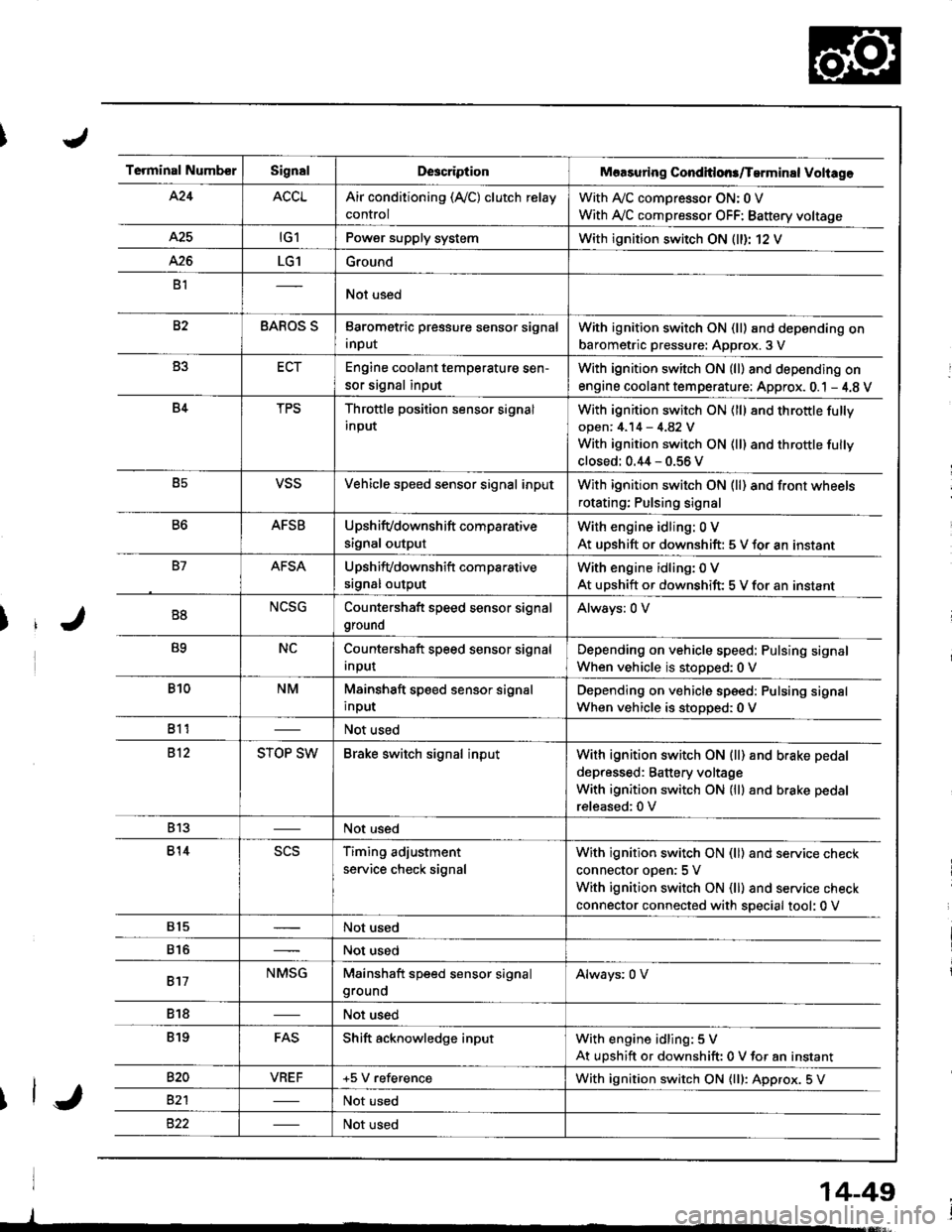
Terminal NumberSignalDescriptionMaasuring Conditlons/Tarminal Voliage
424ACCLAir conditioning (Ay'C) clutch relay
control
With A,/C comDressor ON: 0 V
With Ay'C compressor OFF: Battery voltage
A25tG1Power supply systemWith ignition switch ON (ll)r 12 V
426LG1Ground
B1Not used
82BAROS SBarometric pressure sensor signal
input
With ignition switch ON (ll) and depending on
barometric pressure: Approx. 3 V
B3ECTEngine coolant temperature sen-
sor signal input
With ignition switch ON (ll) and depending on
engine coolant tem perature: Approx. 0.1 - 4.8 V
B4TPSThrottle position sensor signal
input
With ignition switch ON (ll) 8nd throttle fully
open: 4.14 - 4.82 V
With ignition switch ON (ll) and throttle fully
closed: 0.44 - 0.56 V
B5VSSVehicle speed sensor signal inputWith ignition switch ON (ll) and front wheels
rotating; Pulsing signal
B6AFSBUpshifvdownshift comparative
signal output
With engine idling: 0 V
At uDshift or downshift: 5 V for an instant
B7AFSAUpshifvdownshift com parative
srgnal output
With engine idling: 0 V
At upshift or downshift: 5 V for an instant
B8NCSGCountershaft speed sensor signal
ground
Always: 0 V
B9NCCountershaft speed sensor signal
Input
Depending on vehicle speed: Pulsing signal
When vehicle is stopped:0 V
B10NMMainshaft speed sensor signal
input
Depending on vehicle speed: Pulsing signal
When vehicle is stoDoed: 0 V
811Not used
812STOP SWBrake switch signal inputWith ignition switch ON {ll) and b.ake pedal
depressed: Battery voltage
With ignition switch ON (lll and brake pedal
released:0 V
813Not used
814scsTiming adjustment
service check signal
With ignition switch ON (ll) and service check
connector oDen:5 V
With ignition switch ON (ll) and service check
connector connected with special tool: 0 V
815Not used
816Not used
817NMSGMainshaft speed sensor signalgroundAlways: 0 V
818Not used
819FASShift acknowledge inputWith engine idling: 5 V
At upshift or downshift: 0 V for an instant
820VBEF+5 V referenceWith ignition switch ON {lll: Approx. 5 V
82'lNot used
Not used
14-49
Page 502 of 1681
u
fj
\*J
14-85
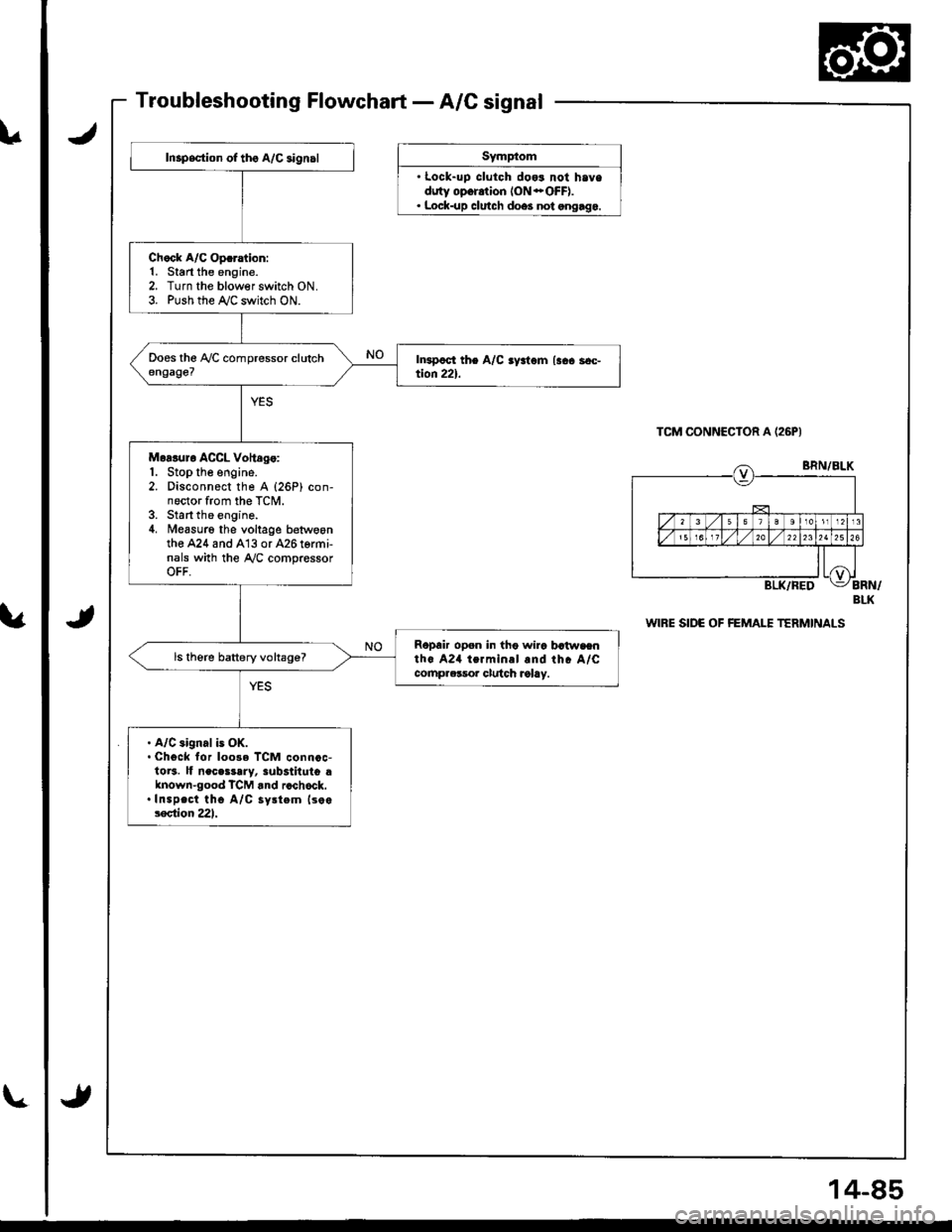
Inspsction of tho A/C aign.l
Ch.ck A/C Op.ration:1. Start the engine.2. Turn the blowerswitch ON.3. Push the r'y'C switch ON.
Moaluro ACCL Voltdg.:1. Stop the engine.2. Disconnect the A {26P) con-nector from the TCM.3. Start the engine.4. Measuro the voltage betwoontho A24 and A13 or 426 termi-nals with the Ay'C compressorOFF.
Ropair open in tho wira batwaenth. A24 termin.l and rhc A/Ccomprclsor clulch ralay.
ls therc battery voltage?
. A/C aignal is OK.. Chgck for loo3e TCM connoc-1013. lf neces3ary, 3ub3tituto dknown-good TCM rnd rcchock..Inspect tho A/C sy.tem lso.lection 221.
JSymp(om
' Lock-uD clutch dog3 not haveduty opor.tion ION *OFF).. Lock-up clutch doe3 not ongago.
TCM CONNECIOR A (26PI
J
BLK
WIRE SIDE OF FEMALE TERMINALS
Page 565 of 1681
Clutch
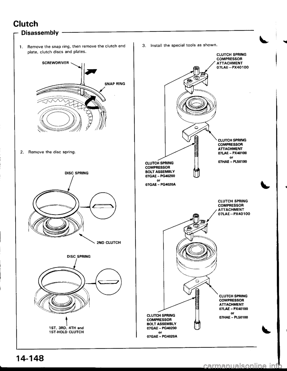
!
Disassembly
1. Remove the snap ring, then remove the clutch end
olate, clutch discs and Plates
SCREWDRIVER
SNAP RING
2. Remove the disc spring.
2ND CLUTCH
I
I'tsT, 3RO, 4TH andlST.HOLD CLUTCH
DISC SPRING
DISC SPRING
14-148
3. Install the special tools as shown.
CLU'CH SPRINGCOMPRESSORBOLT ASSEMBLY07GAE - PG,O200olO'GAE - PG4I}2OA
CI-UTCH SPRINGCOMPRESSORBOLT ASSEMBLY07GAE - PG40200otOTGAE - PG4O2OA
CLUTCH SPRINGCOMPRESSORATTACHMENT07LAE -PX40100
CLUTC}I SPRINGCOMPRESSORATTACHMENT07LAE - PX0100ot07HAE - P150100
CLUTCH SPRINGCOMPRESSORATTACHMENT07LAE-PX40100
CLUTCH SPRINGCOMPRESSORATTACHMENT07LAE - PX(}Iq)ol07HAE - P150100
Page 568 of 1681
I
t
I
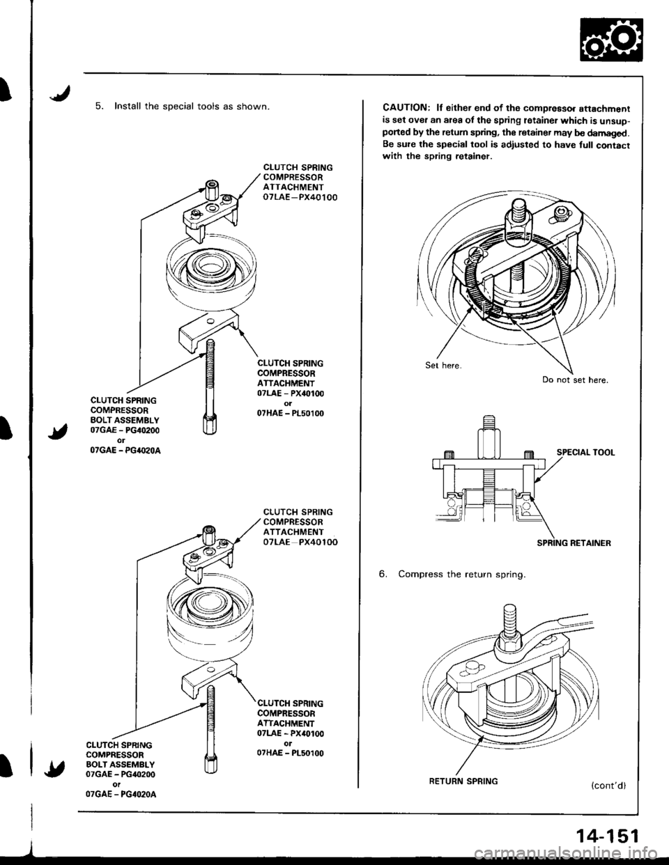
5. Install the sDecial tools as shown.
CLUTCH SPRINGCOMPRESSORBOLT ASSEMBLY07GAE - PG40200olOTGAE - PG4.I'zOA
CLUTCH SPRINGCOMPRESSORBOLT ASSEMBLY07GAE - PG40200
OTGAE - PGIO2OA
CLUTCH SPRINGCOMPRESSORATTACHMENToTLAE -PX40100
CLUTCH SPRINGCOMPRESSORATIACHMENT07LAE - PX40100o107HAE - PL50100
CLUTCH SPRINGCOMPRESSORATTACHMENTOTLAE PX4OlOO
SPRINGCOMPRESSORATTACHMENT07LAE - PX40100ol07HAE - PL50100
l
CAUTION: lf either end of th6 compreaso. attachmentis set over an area of the spring lstainer which is unsuo-ported by the retum spring, the retainer may b€ damaged.Be su?e the special tool is adiusted to have full contacrwith the spring retainer.
SPECIAL TOOL
RETAINER
6. Compress the return spring.
Do not set here.
RETURN SPRING
14-151
Page 684 of 1681
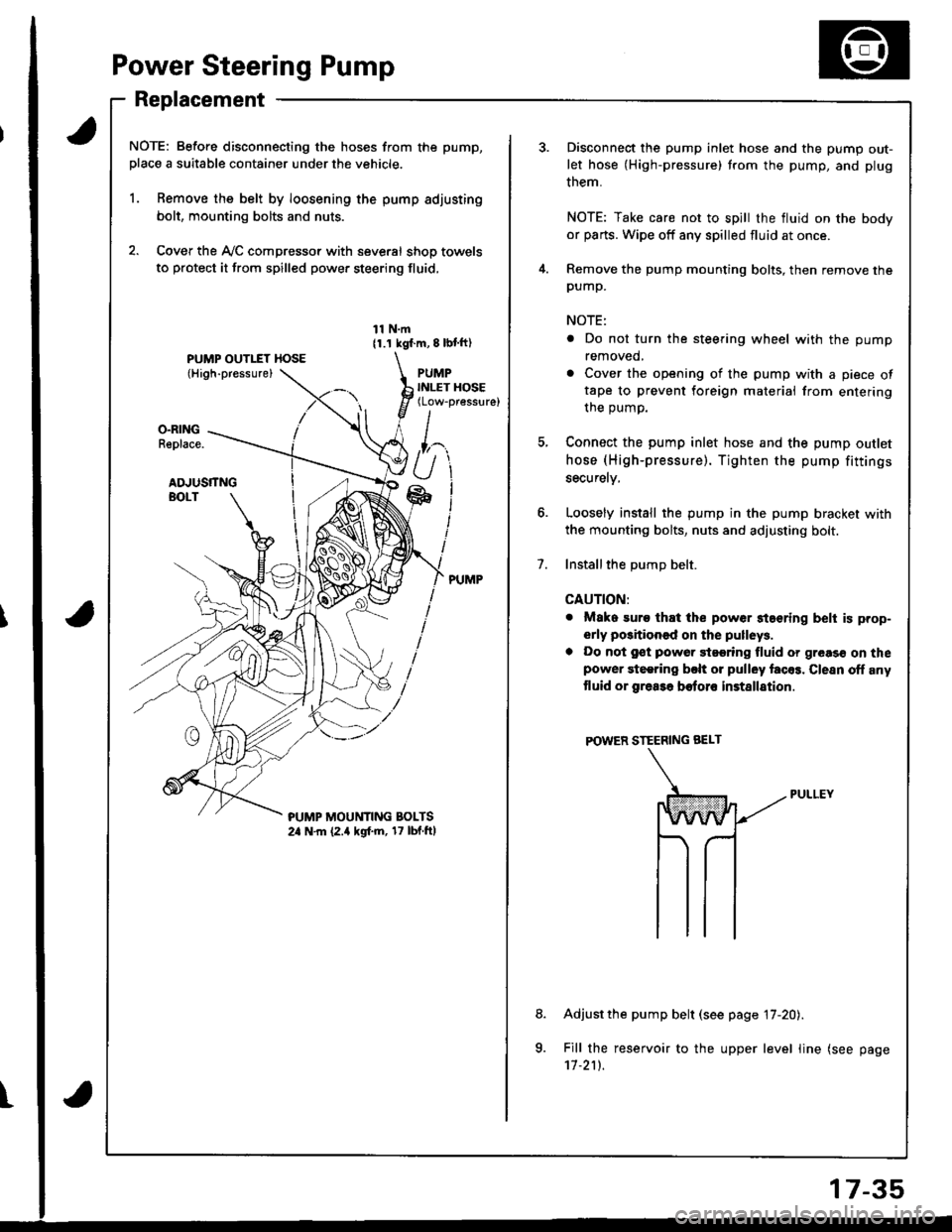
Power Steering Pump
Replacement
NOTE: Before disconnecting the hoses from the pump,
place a suitable container under the vehicle.
1. Remove the belt by loosening the pump adjusting
bolt, mounting bolts and nuts.
2. Cover the Ay'C compressor with several shop towels
to protect it from spilled power steering fluid,
11 N.m11.1 kgf.m, 8 lbl ft)
PUMPINLET HOSE(Low-pressure)
O.RINGReplace.
ADJUSTTNGBOLT
?UMP MOUt'lTlNG BOLTS2a N.m (2.a kgf.m, 17 lbf.ftl
t
7.
Disconnect the pump inlet hose and the pump out-
let hose (High-pressure) trom the pump, and plug
them.
NOTE: Take care not to spill the fluid on the body
or parts. Wipe off any spilled fluid at once.
Remove the pump mounting bolts, then remove thepump.
NOTE:
. Do not turn the steering wheel with the pump
removed,
. Cover the opening of the pump with a piece oftape to prevent foreign materiai from entering
the oumo.
Connect the pump inlet hose and the pump outlet
hose (High-pressure). Tighten the pump fittings
securelv,
Loosely install the pump in the pump bracket with
the mounting bolts, nuts and adjusting bolt.
Installthe DumD belt.
CAUTION:
. Mako suro that the power staering belt is prop-
erly positioned on the pulleys.
a Do not gst powor 9t99ring fluid or greas€ on thepower steering bclt or pulley facos. Clesn off any
tluid or grea3a botoro installation
POWER STEERING BEI-T
Adjust the pump belt (see page 17-20).
Fill the reservoir to the upper level line (see page'11.211.
8.
a
17-35
Page 732 of 1681
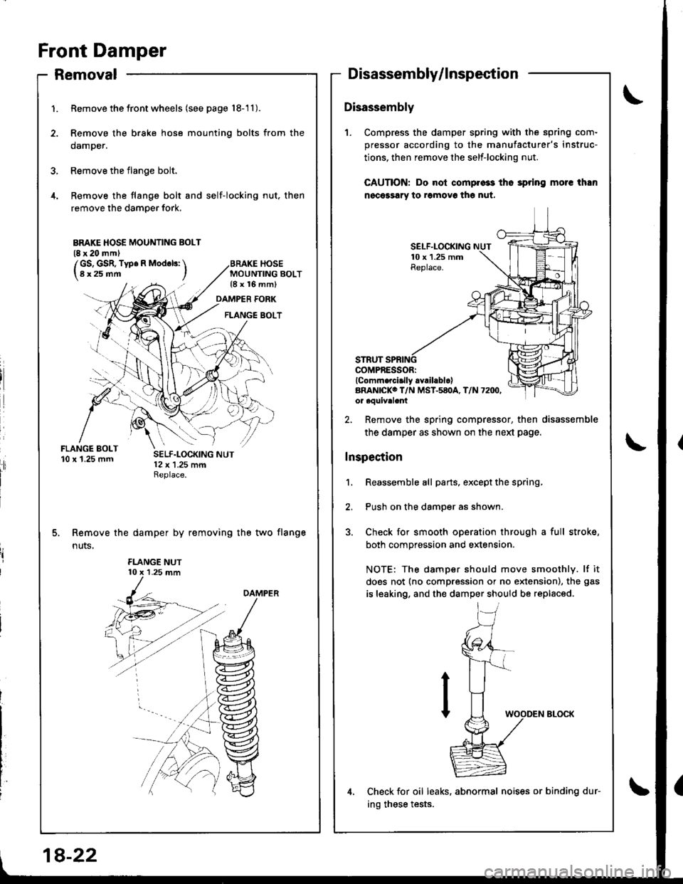
Front Damper
FLANGE BOLT10 x'1.25 mm
1.
4.
Removal
Remove thefrontwheels (see page 18-'11).
Remove the brake hose mounting bolts from the
damper.
Remove the flange bolt.
Remove the flange bolt and self-locking nut, then
remove the damper fork.
MOUNTING BOLT{8 x 16 mm)
Disassembly/lnspection
Disassembly
1. Compress the damper spring with the spring com-
pressor according to the manufacturer's instruc-
tions. then remove the self-locking nut.
CAUTION: Do nol compros3 tho 3pring morc than
nocessary to romovo th€ nut.
DAMPER FORK
FLANGE BOLT
SELF.LOCKING10 x 1.25 mmReplace.
COMPRESSORIlComm.rci.lly .Yrll.blclARAN|CKO T/N MST-580A, T/N 72IX',or aouivalant
Remove the damper by removing the two flange
n uts.
2, Remove the spring compressor, then disassemble
the damper as shown on the neld page.
Inspection
1. Reassemble all parts, exceptthe spring,
2, Push on the damper as shown.
3. Check for smooth operation through a full stroke,
both compression and extension.
NOTE: The damper should move smoothly. lf it
does not (no compression or no extension), the gas
is leaking, and the damper should be replaced.
Check for oil leaks, abnormal noises or binding dur-
ing these tests.
BMKE HOSE MOUNTING BOLT(8 x 20 mml
/GS, GSR, Type R Mod6ls: \l8x25mm I
18-22