Compressor HONDA INTEGRA 1998 4.G Owner's Manual
[x] Cancel search | Manufacturer: HONDA, Model Year: 1998, Model line: INTEGRA, Model: HONDA INTEGRA 1998 4.GPages: 1681, PDF Size: 54.22 MB
Page 734 of 1681
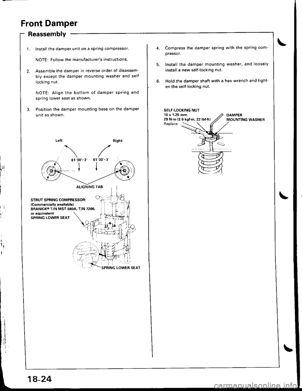
Front Damper
Reassembly
Install the damper unit on a spring compressor'
NOTE: Follow the manufacturer's instructions.
Assemble the damper in reverse order of disassem-
bly except the damper mounting washer and selt
locking nut.
NOTE: Align the bottom of damper spring and
spring lower seat as shown.
Position the damper mounting base on the damper
unit as shown.
61'30'13'
I
STRUT SPRING COMPRESSOR:
{Commercially available)BBANICKO T/N MST-580A, T/N 7200,or equivalentSPRING LOWER SEAT
ALIGNINGTAB
GfL
lr
rl
I
1a-24
Compress the damper spring with the sprlng com-
pressor.
Install the damper mounting washer, and loosely
install a new self-locking nut.
Hold the damper shaft with a hex wrench and tight-
en the self-locking nut.
SELF-LOCKING NUT10 x 1.25 mm29 N.m {3.0 kgt.m, 22 lbI.ft)Replace.
Page 747 of 1681
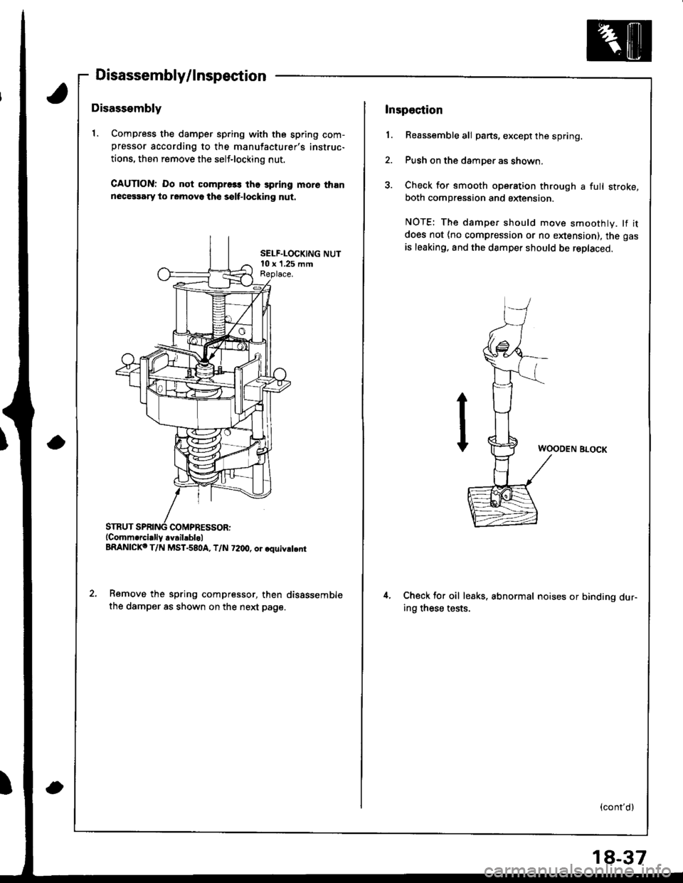
Disassembly/lnspection
Disassembly
1. Compress the damper sp.ing with the spring com-pressor according to the manufacturer's instruc-
tions, then remove the self-locking nut.
CAUTION: Do not compre3s the spring more thannecessary to removo th€ sslf-locking nut.
SELF.LOCKING NUT10 x '1.25 mmReplace.
COMPRESSOR:(Comm.rcially.v.il.blol
BRANICKo T/N MST-580A, T/N 72dt, or.quiv.t.nr
Remove the spring compressor, then disSssemble
the damper as shown on the next page.
Inspection
1. Reassemble all parts, except the spring.
2. Push on the damper as shown.
3. Check for smooth operation through a full stroke,both compression and sxtension.
NOTE: The damper should move smoothly. lf it
does not (no compression or no enension), the gas
is leaking. and the damper should be replaced.
WOODEN BLOCK
4.Check tor oil leaks. abnormal noises or binding dur-ing these tests.
(cont'd)
18-37
Page 749 of 1681
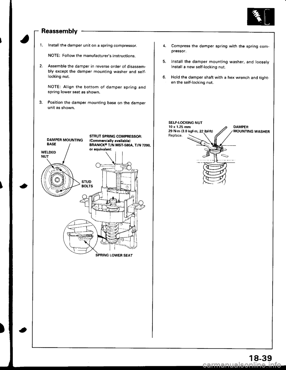
Reassembly
Installthe damper unit on a spring compressor.
NOTE: Followthe manufacturer's instructions.
Assemble the damper in reverse order of disassem-
bly except the damper mounting washer and self-locking nut.
NOTE: Align the bottom of damper spring andspring lower seat as shown.
Position the damper mounting base on the damper
unit as shown.
STRUT SPRING COMPRESSOR:lComm.rci.llv availabls)BRANICKO T/N MST.58OA, T/N 7200,or oquivalent
DAMPER MOUNTTNG
a
a
18-39
Compress the damper spring with the spring com-pressor.
lnstall the damper mounting washer, and loosely
install a new self-locking nut.
Hold the damper shaft with a hex wrench and tight-en the self-locking nut.
SELF.LOCKING NUT10 x 1.25 mm29 N.m (3.0 kstm.22 lbl.ft)Replace.
Page 767 of 1681
1.
8.
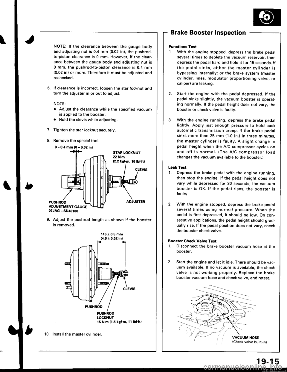
NOTE: lf the clearance between the gauge body
and adjusting nut is 0.4 mm (0.02 in), the pushrod-
to-piston clearance is 0 mm. However, if the clear-
ance between the gauge body and adjusting nut is
0 mm, the pushrod-to-piston clearance is 0.4 mm(0.02 in) or more. Therefore it must be adjusted and
rechecked.
lf clearance is incorrect, loosen the star locknut and
turn the adjuster in or out to adjust.
NOTE:
. Adjust the clearance while the specified vacuum
is applied to the booster.
. Hold the clevis while adjusting.
Tighten the star Iocknut securely.
Remove the special tool.
0 - o.il mm l0 - 0.02 inl
Brake Booster Inspection
Functions Tgst
1. With the engine stopped, depress the brake pedal
several times to deplete the vacuum reservoir, then
depress the pedal hard and hold it for 15 seconds. ll
the pedal sinks, either the master cylinder is
bypassing internally; or the brake system (master
cylinder, lines, modulator proportioning valve, orcaliper) are leaking.
Start the engine with the pedal depressed. lf thepedal sinks slightly, the vacuum booster is operat-
ing normally. lf the pedal height does not vary, the
booster or check valve is faulty.
With the engine running, depress the brake pedal
lightly. Apply just enough pressure to hold back
automatic transmission creep, lf the brake pedal
sinks more than 25 mm (1.0 in.) in three minutes,
the master cylinder is faulty. A slight change inpedal height when the A,,/C compressor cycles on
and off is normal. (The A/C compressor load
changes the vacuum available to the booster.)
Leak Test
1. Depress the brake pedal with the engine running,
then stop the engine. lf the pedal height does not
vary while depressed for 30 seconds, the vacuum
booster is OK. lf the pedal rises, the booster is
fau lty.
2. With the engine stopped, depress the brake pedal
several times using normal pressure. When thepedal is first depressed, it should be low. On con-
secutive applications, the pedal height should grad-
ually rise. lf the pedal position does not vary, check
the booster check valve.
Boostor Ch€ck Valve T6st
1. Disconnect the brake booster vacuum hose at the
booster,
Start the engine and let it idle. There should be vac-
uum available. It no vacuum is available. the check
valve is not working properly. Replace the brake
booster vacuum hose and check valve, and retest.
VACUUM HOSE(Check valve built-in)
STAR LOCKNUT22 t{.m12.2 ksl.m, 16lbf.ftl
cLEVtS
ADJUSTER
ADJUSTMENT GAUGE07JAG - SD40t00
9. Adjust the pushrod length as shown if the booster
is removed.
1161 0.5 mm14.61 0.02 inl
PUSHRODLOCKNUT15 N m 11.5 kgf m, 11 lbf'ftl
10. Instali the master cylinder.
Page 1019 of 1681
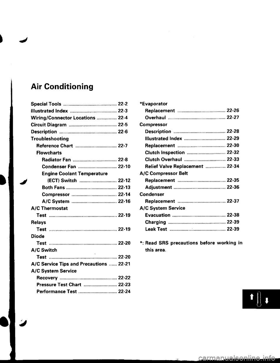
Air Gonditioning
+Evaporator
Repf acement .........22-26
Overhauf ................22-27
Compressor
Description ............22-28
lf lustrated f ndex ............................... 22-29
Replacement .........22-30
Cf utch Inspection ....................... ...... 22-32
Cf utch Overhau1 ........................ ....... 22-33
Ref ief Vaf ve Replacement ............... 22-34
A/C Compressor Belt
Repf acement .........22-35
Adiustment ............22-36
Condenser
Repf acement .........22-37
A/C System Service
Evacuation .............22-38
Charging ................22-39
Leak Test ...............22-39
*: Read SRS precautions before working in
this area.
Page 1021 of 1681
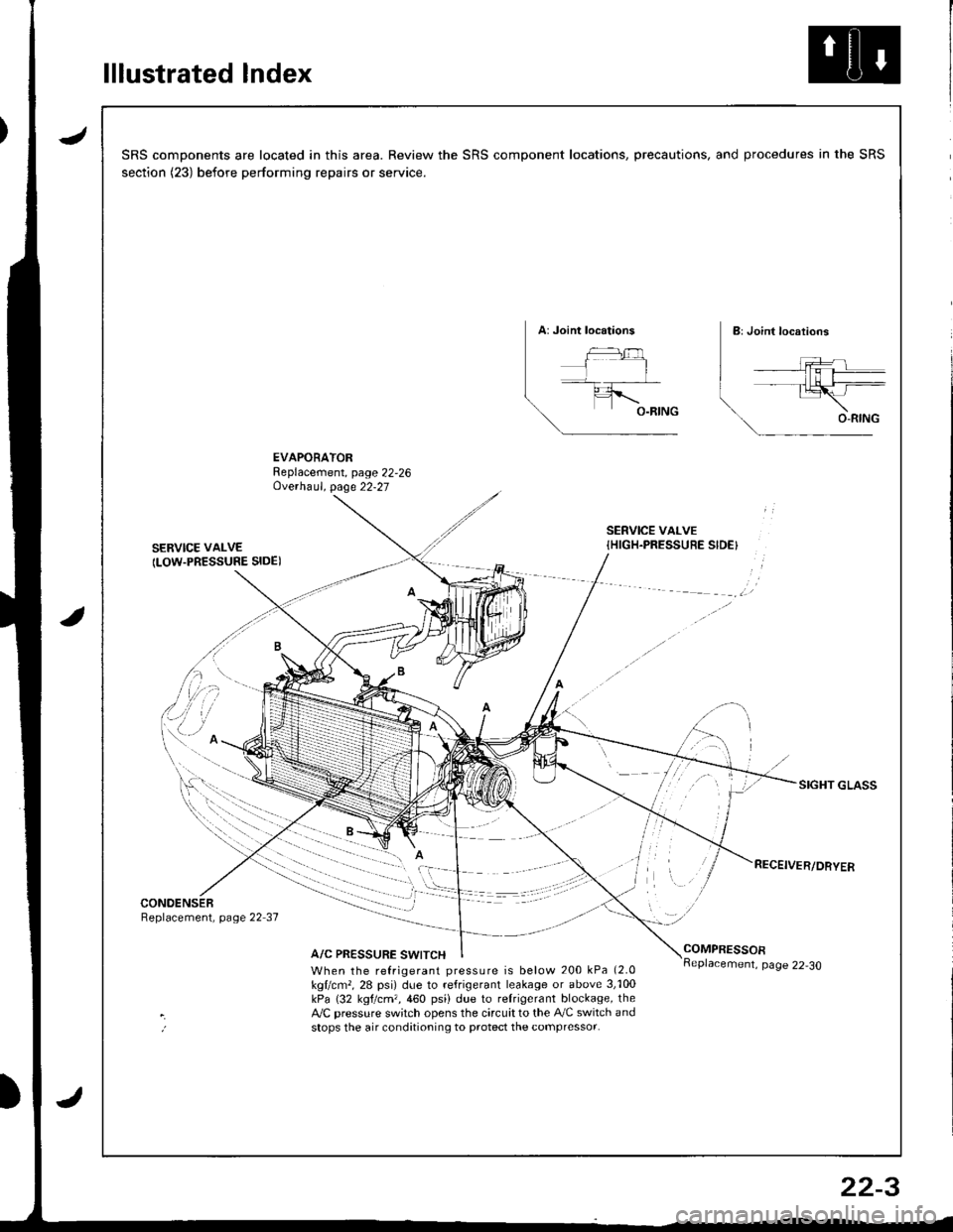
lllustrated Index
JSRS components are located in this area. Review the SRS component locations, precautions, and procedures in the SRS
section (23) before performing repairs or service.
EVAPORATORReplacement, page 22,26Ove.haul. page 22-27
SERVICE VAI-VE
ILOW.PRESSURE SIDE)
SERVICE VALVE{HIGH.PRESSUEE SIDE}
SIGHT GLASS
CONOENSERReplacement, page 22 37
A/C PRESSURE SWITCHCOMPRESSOR
When the refrigerant pressure is below 200 kPa (2.0
kgllcm,, 28 psi) due to refrigerant leakage or above 3,'100kPa (32 kgtcm,,460 psi) due to relrigerant blockage, theA,/C pressure sw;tch opens the circuit to the A,/C switch andstops the air conditioning to protect the compressor.
page 22-30
22-3
Page 1022 of 1681
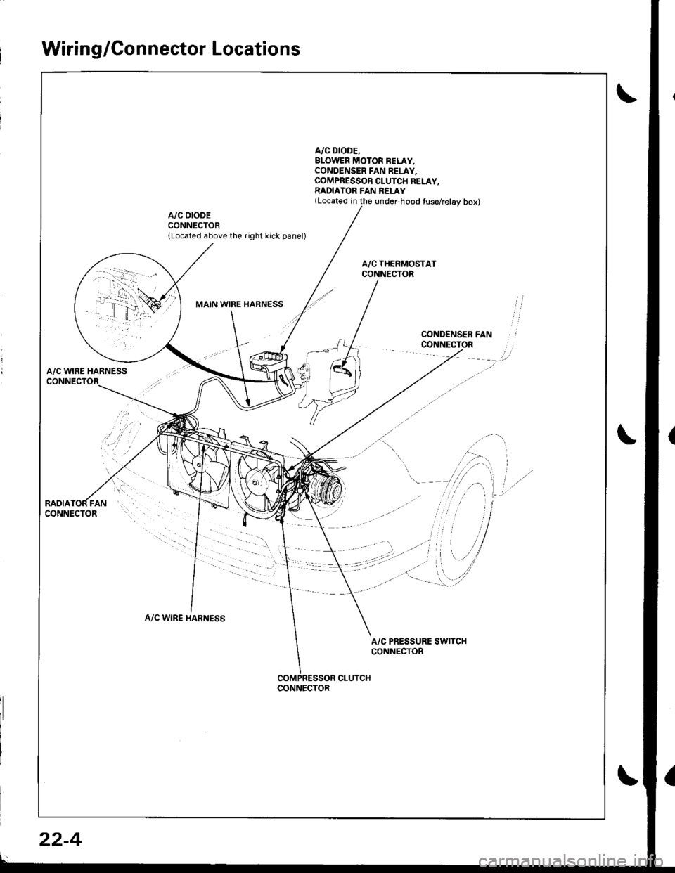
Wiring/Connector Locations
A/C DIODE.BLOWER MOTOR BELAY,CONOENSER FAN RELAY.COMPRESSOR CLUTCH RELAY,RADIATOR FAN REI-AY(Located in the under-hood tuse/relay box)
A/C DIODECONNECTORlLocated above the right kick panel)
MAIN WIBE HARNESS
A/C WINE HARNESS
A/C WIRE HARNESS
A/C PRESSURE SWITCHCONNECTOR
CLUTCHCONNECTOR
22-4
Page 1024 of 1681
Description
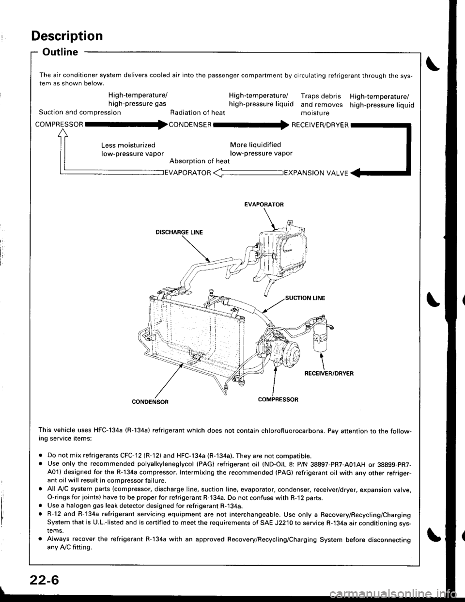
Outline
The air conditioner system delivers cooled air into the passenger companment by circulating retrigerant through the sys-
tem as shown below.
High-temperature/ H ig h-tem peratu rel Traps debris High-temperature/high-pressure gas high-pressure liquid and removes high-pressure liquidSuction and compression Radiation of heat moisture
covpnEsson -tl4con oetsen -rr{ REcEIvER/DRvER
More liqu idified
low-pressure vapor
Absorption of heat
Less moisturized
low-pressure vapor
EVAPORATOR -TEXPANS|ON VALVE
EVAPORATOR
CONDENSOR
This vehicle uses HFC-134a (R-134a) refrigerant which does not contain chlorofluorocarbons. Pay attention to the follow-ing service items:
. Do not mix refrigerants CFC-12 (R-12) and HFC-134a (R-134a). They are not compatible.. Use only the recommended polyalkyleneglycol (PAG) refrigerant oil (ND-OIL 8: P/N 38897-PR7-A01AH or 38899-PR7-A01) designed for the R-134a compressor. Intermixing the recommended (PAG) refrigerant oil with any other refriger-ant oil will result in compressor failure.
. All AVC system parts (compressor, discharge line, suction line. evaporator, condenser, receiver/dryer, expansion valve.O-rings for joints) have to be proper for refrigerant R-134a. Do not confuse with R-12 parts.
. Use a halogen gas leak detector designed for refrigerant R-134a.. R-12 and R-134a refrigerant servicing equipment are not interchangeable. Use only a Recovery/Recycling/ChargingSystem that is U.L.-listed and is certified to meet the requirements of SAE J2210 to service R-134a air conditioning sys-tems.
. Always recover the refrigerant R-134a with an approved Recovery/Recycling/Charging System before disconnectingany Ay'C fitting.
22-6
Page 1025 of 1681
J
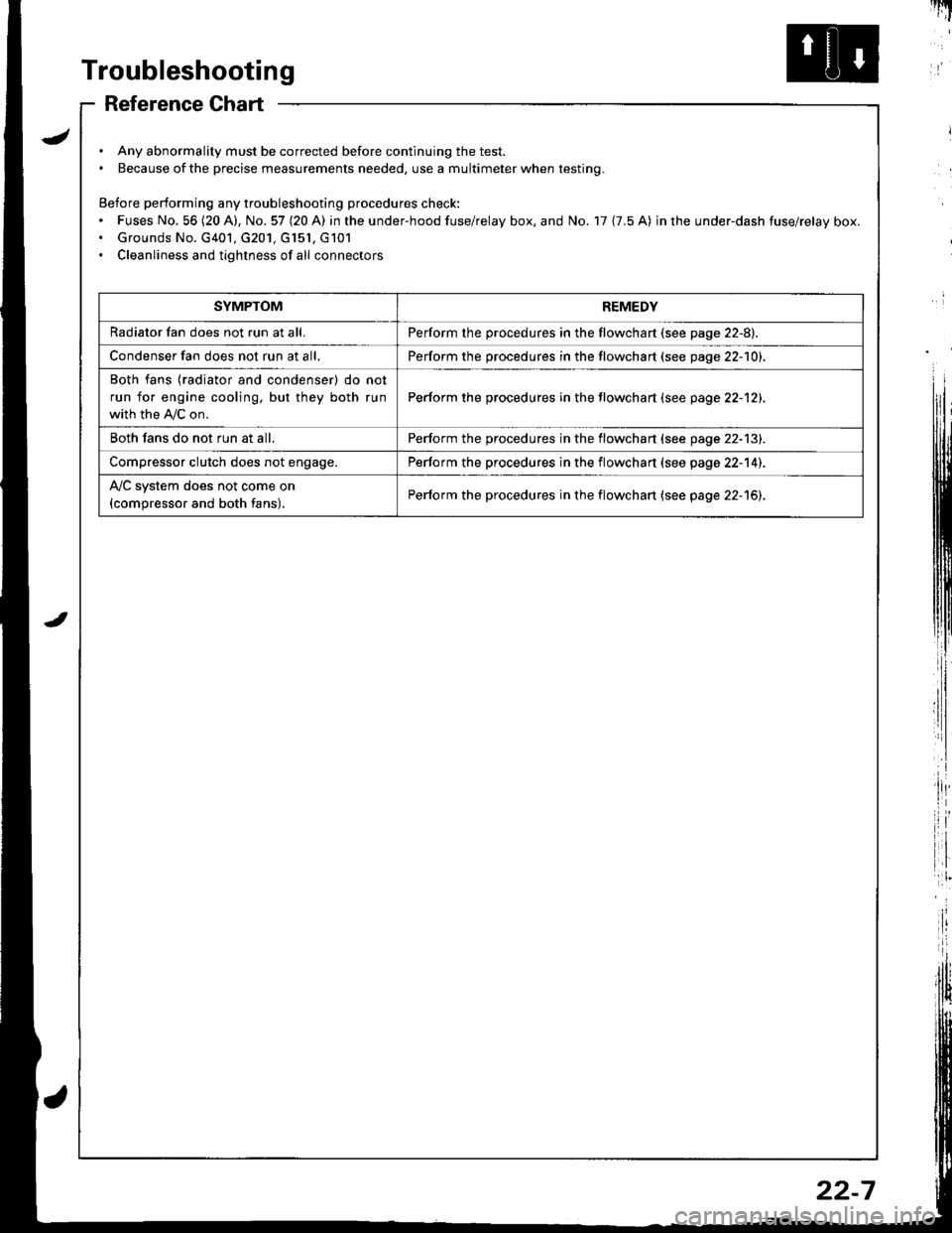
Troubleshooting
Reference Chart
. Any abnormality must be corrected before continuing the test.. Because of the precise measurements needed, use a multimeter when testing.
Before performing any troubleshooting procedures check:. Fuses No, 56 (20 A), No. 57 (20 A) in the under-hood fuse/relay box, and No. 17 {7.5 A) in rhe under-dash fuse/relay box.. Grounds No. G401, G201, G151, G101. Cleanliness and tightness of all connectors
I'IT
I
I
SYMPTOMREMEDY
Radiator fan does not run at all.Perform the procedures in the flowchart {see page 22-8).
Condenser fan does not run at all,Perform the procedures in the flowchart (see page 22-1O1.
Both fans {radiator and condenser) do not
run for engine cooling, but they both run
with the IVC on.
Perform the procedures in the tlowchart (see page 22-12).
Both fans do not run at all.Perform the procedures in the flowchart (see page 22-13).
Compressor clutch does not engage.Perform the procedures in the flowchart (see page 22-14).
l'lc system does not come on
{compressor and both fans).Perform the procedures in the flowchart (see page 22-15).
22-7
Page 1032 of 1681
Troubleshooting
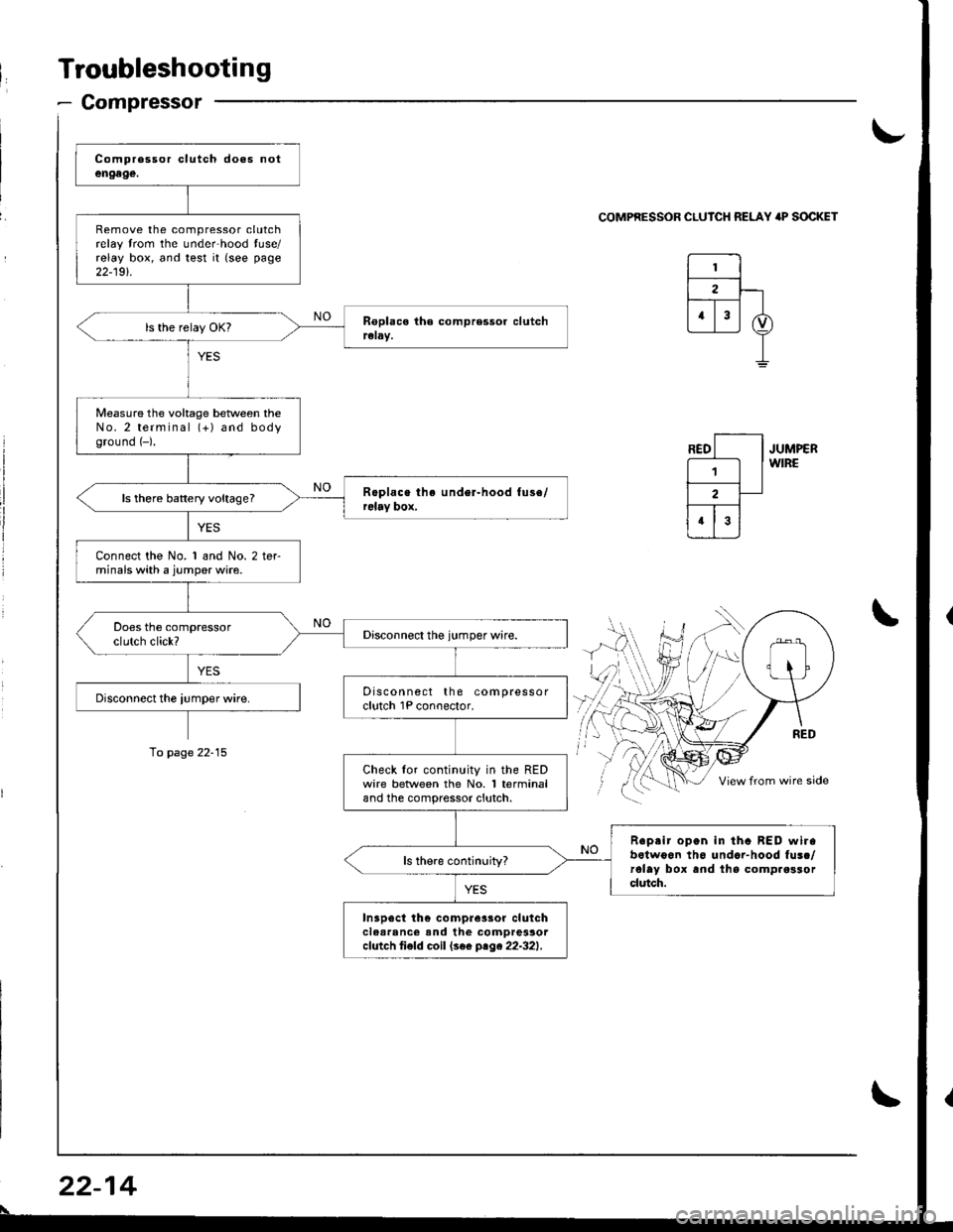
- Compressor
Remove the compressor clutchrelay trom the unde.hood tuse/relay box, and test it {see page
22-19t.
Measure the voltage beNveen theNo.2 terminal (+) and bodyground (-).
ls there battery voltage?
Connect the No. 1 and No. 2 terminals with a jumper wire.
Discon nect the compressorclutch 1P conoector.
Check lor continuity in the REDwire betlveen the No. 1 terminaland the compressor clutch.
Reprir open in tha BED wirabotwoon th6 undar-hood fusc/rolay box and lhs comp.osrorclutch.
In3p6ct th€ compre3sor clulchclear'nc€ and the comDressorcfutch ti€fd coil (se€ ptge22-321.
\-
COMPRESSOR CLUICH RELAY 'P SOCKET
JUMPERWIRE
\
To page 22-15
22-14
\