Head HONDA INTEGRA 1998 4.G Repair Manual
[x] Cancel search | Manufacturer: HONDA, Model Year: 1998, Model line: INTEGRA, Model: HONDA INTEGRA 1998 4.GPages: 1681, PDF Size: 54.22 MB
Page 915 of 1681
Headliner
Replacement (cont'd)
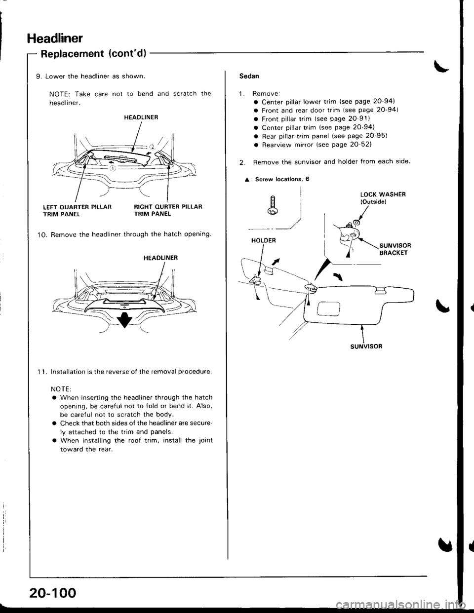
LEFT OUARTER PILLARTRIM PANEL
9. Lower the headliner as shown.
NOTE: Take care not to bend and scratch the
head liner.
RIGHT OURTER PILLARTRIM PANEL
1O. Remove the headliner through the hatch opening
1 1. Installation is the reverse of the removal procedure.
NOTE:
a When inserting the headliner through the hatch
opening, be careful not to lold or bend it. Also,
be careful not to scratch the body.
a Check that both sides o{ the headliner are secure'
ly attached to the trim and panels.
a When installing the rool trim, install the ioint
toward the rear.
HEAOLINER
HEADLINER
20-100
Sedan
1.Rem ove:
a Center pillar lower trim {see page 20-94)
a Front and rear door trim (see page 20-94)
a Front pillar trim lsee page 20 9'.
a Center pillar trim {see page 20 94)
a Rear pillar trim panel (see page 20-95)
a Rearview mirror (see page 20 52)
Remove the sunvisor and holder from each side.
: Screw locations, 6
elA]*)
HOLDER
suNVlsoR
LOCK WASHER
lOutside)
,al
(
Page 917 of 1681
Headliner
Replacement (cont'd)
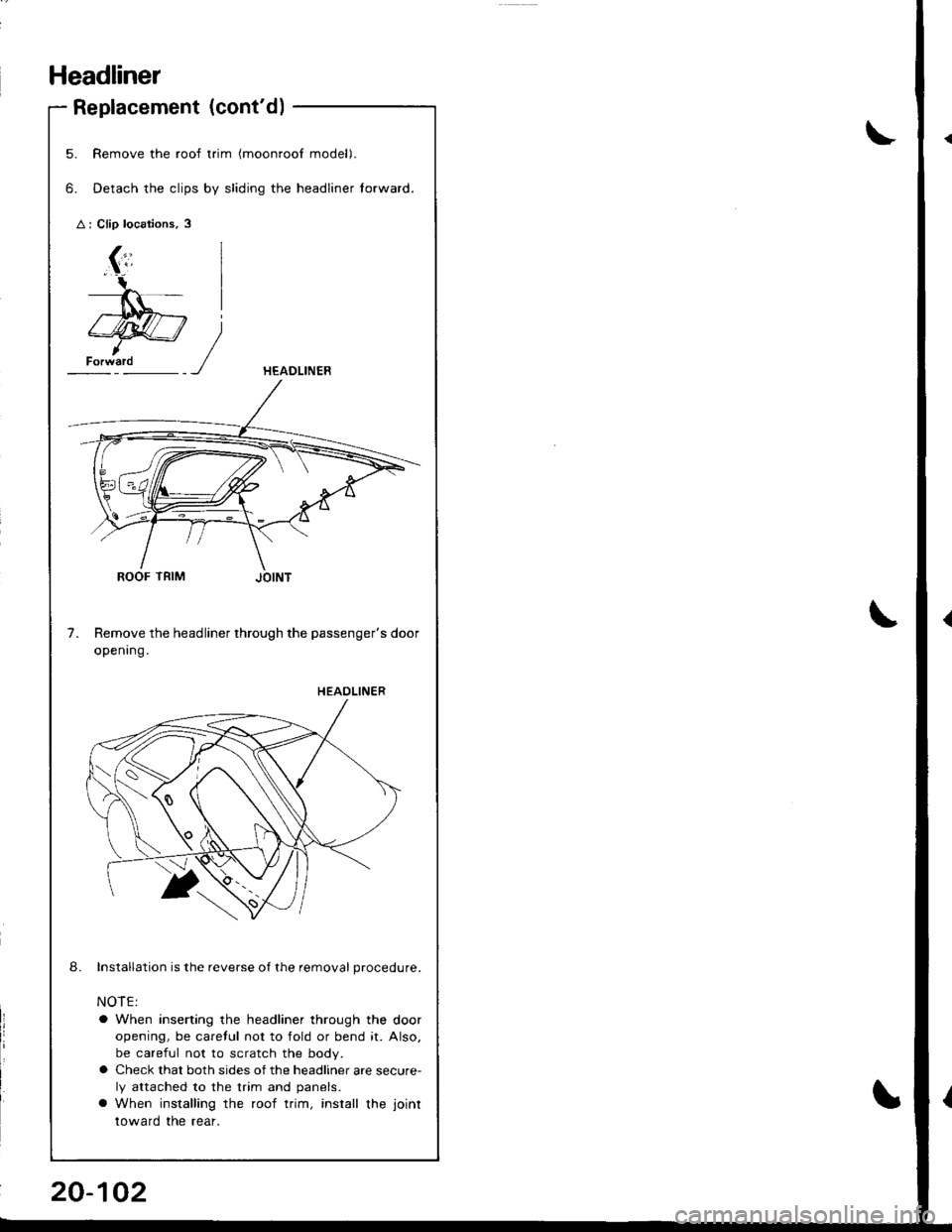
5.
6.
Remove the roof trim (moonroof model).
Detach the clips by sliding the headliner torward.
ROOF TRIM
Remove the headliner through the passenger's door
openrng.
Installation is the reverse of the removal procedure.
NOTE:
a When inserting the headliner through the door
opening, be caretul not to fold or bend it. Also,
be careful not to scratch the body.
o Check that both sides of the headliner are secure-
ly attached to the trim and panels.
a When installing the roof trim, install the joint
toward the rear.
)
7.
8.
HEAOLINER
HEAOLINER
Page 921 of 1681
Seats
Front Seat Disassembly and Reassembly
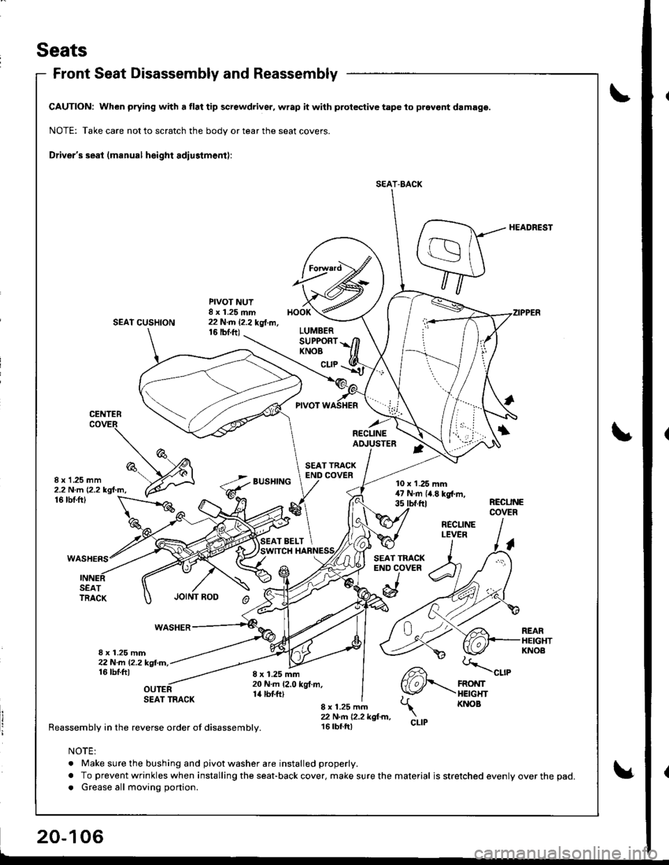
CAUTION: When prying with a tlat tip screwdriver, wrap it with protective tape to pravont damage.
NOTE: Take care not to scratch the body or tear the seat covers.
Driver's seat (manual height adiustment):
HEADREST
SEAT CUSHION
PIVOT NUT8 x 1.25 mm22 N.m 12.2 kg{.m,16 |bnft)
BUSHING
HOOK
LUMBERSUPPORTKNOB
cuP
CENTER
RECLINEAI!USTER
8 x 1 .25 mm2.2 N.m {2.2 kgf.m,10 x 1.25 mm47Nm{4.Ekgl.m,35 tbt.ftl
CLIP
16 tbf.ftlRECUNECOVER
SEATTRACK
WASHER
8 x 1.25 mm22N-m l2.2kgl.m,16 tbtftl
SEAT TRACK
Reassembly in the reverse order of disassembly.
REARHEIGHTKNOA
8 x 1.25 mm20 N.m 12.0 kgt.m,14 tbtft)
CLIP
8 x 1.25 mm22 N.n 12.2 kgl.m,16 tbf.tt)
NOTE:
. Make sure the bushing and pivot washer are installed properly.
a To prevent wrinkles when installing the seat-back cover. make sure the material is stretched evenly over the pad.
a Grease all moving portion.
SEAT-BACK
RECLINELEVER
Page 923 of 1681
Seats
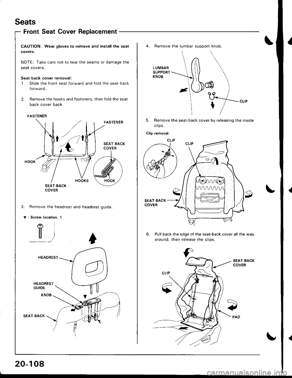
Front Seat Cover Replacement
CAUTION: Wea. gloves to remove and install the seat
covers.
NOTE: Take care not to tear the seams or damage the
seat covers.
Seat-back cover removal:'l- Slide the {ront seat forward and Jold the seat back
forward.
2. Remove the hooks and fasteners, then fold the seat
back cover back.
FASTENER
SEAT-8ACKCOVER
Remove the headrest and headrest
Screw
o
FASTENER
gu rd e.
location, 1
)
HEADREST
HEADRESTGUIDE
KNOB
SEAT.BACK
20-108
o
4. Remove the lumbar support knob.
LUMBARSUPPORTKNOB
J
tf*,,
5. Remove the seat-back cover by releasing the inside
clrps -
Clip removal:
SEAT-BACKCOVER
6. Pull back the edge of the seat-back cover all the way
around. then release the clios.
SEAT,BACKCOVER
Page 964 of 1681
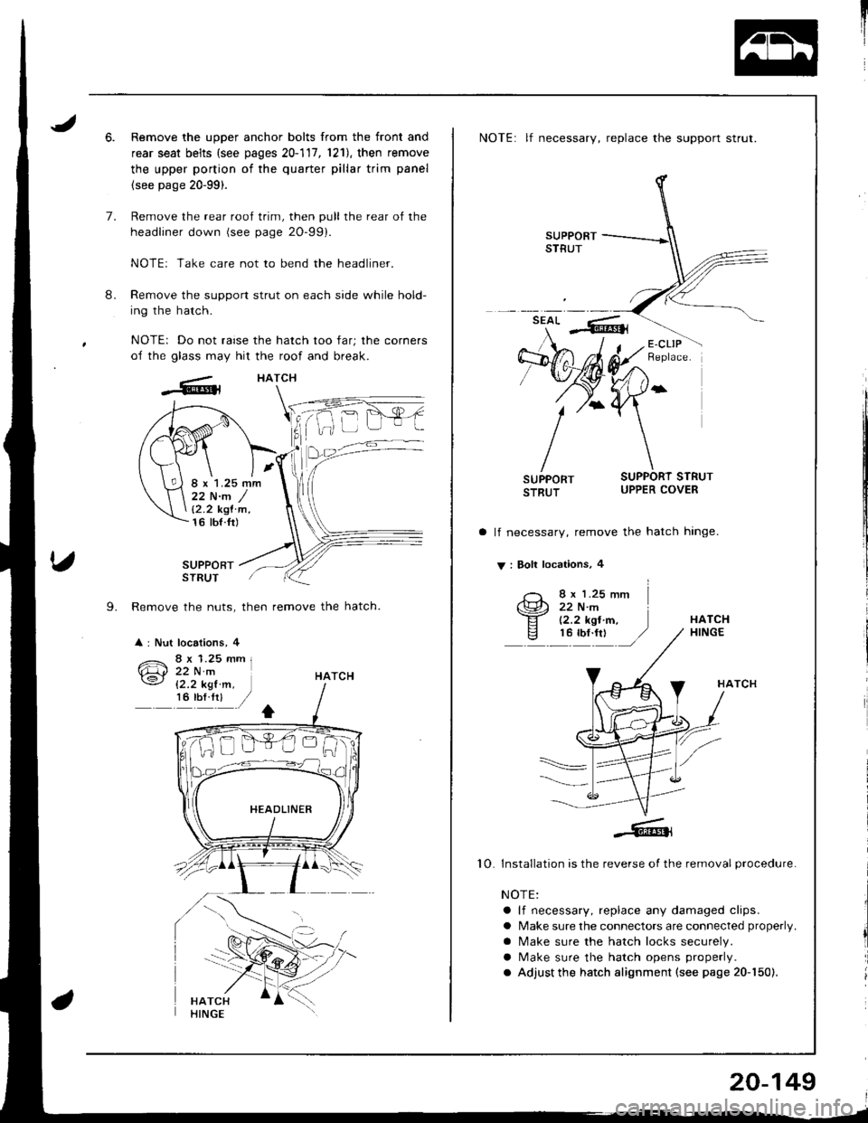
6.Remove the upper anchor bolts from the front and
rear seat belts (see pages 20-111,1211, then remove
the upper portion of the quarter pillar trim panel
(see page 20-99).
Remove the rear roof trim, then pull the rear of the
headliner down (see page 2O-99).
NOTE: Take care not to bend the headliner.
Remove the support strut on each side while hold-
ing the hatch.
NOTE: Do not raise the hatch too far; the corners
of the glass may hit the roof and break.
HATCH
8.
7.
SUPPORTSTRUT
L Remove the nuts, then remove the hatch.
: Nut locations, 4
22 N.m /12.2 kgl'm,16 tbt.fr)
HATCH
NOTE: lf necessary, replace the support strut.
lf necessary, remove the hatch hinge.
V : Boll locations, 4
I x 1.25 mm22 N.m(2.2 kgl.m,HATCH
10
HATCH
Installation is the reverse of the removal procedure.
NOTE:
a lf necessary, replace any damaged clips.
a Make sure the connectors are connected properly.
a N4ake sure the hatch locks securely.
a Make sure the hatch opens properly.
. Adjust the hatch alignment (see page 20-150).
20-149
Page 1054 of 1681
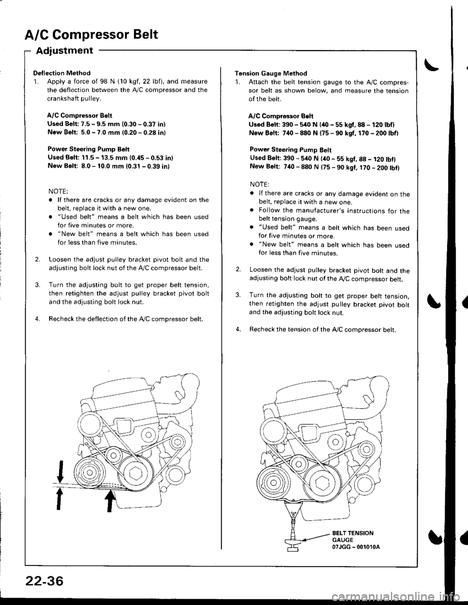
A/C Compressor Belt
Adiustment
Dellection Method
1. Apply a force of 98 N i10 kgf, 22 lbf), and measure
the deflection between the A,/C compressor and the
crankshaft pullev.
A/C Compressor Belt
Used Belt: 7.5 - 9.5 mm (0.30 - 0.37 in)
New Beli: 5.0 - 7.0 mm (0.20 - 0.28 in)
Power Steering Pump Belt
Used Bslt: 11.5 - 13.5 mm (0.i15 - 0.53 in)
New Belt: 8.0 - 10.0 mm (0.31 - 0.39 in)
NOTE:
. lf there are cracks or any damage evident on the
belt, replace it with a new one.
. "Used belt" means a belt which has been used
for five minutes or more.
. "New belt" means a belt which has been used
for less than five minutes.
Loosen the adjust pulley bracket pivot bolt and the
adjusting bolt lock nut of the lVC compressor belt.
Turn the adjusting bolt to get proper belt tension,
then retighten the adjust pulley bracket pivot bolt
and the adjusting bolt lock nut.
Recheck the deflection of the Ay'C compressor belt.
22-36
Tension Gauge Method
1. Attach the belt tension gauge to the Ay'C compres-
sor belt as shown below, and measure the tension
of the belt.
A/C Comprossor Belt
Used Belt: 390 - 5/rc N (4O - 55 kgf. 88 - 120 lbf)
New Bslt: 7,10 - 880 N (75 - 90 kgf, 170 - 200 lbf)
Power Steering Pump Belt
Used Belt: 390 - 540 N (ito - 55 kgl, g8 - i20 tbtlNew Belt: 740 - 880 N (75 - 90 kgt, 170 - 200 tbtl
NOTE:
. lf there are cracks or any damage evident on thebelt, replace it with a new one.. Follow the manufacturer's instructions for thebelt tension gauge.
. "Used belt" means a belt which has been usedfor five minutes or more.. "New belt" means a belt which has been usedfor less than five minutes.
Loosen the adjust pulley bracket pivot bolt and theadjusting bolt lock nut of the A,/C compressor belt.
Turn the adjusting bolt to get proper belt tension,then retighten the adjust pulley bracket pivot boltand the adjusting bolt lock nut.
Recheck the tension of the A,/C compressor belt.
3.
BELT TENSIONGAUGE07JGG - 0010'l0a
Page 1058 of 1681
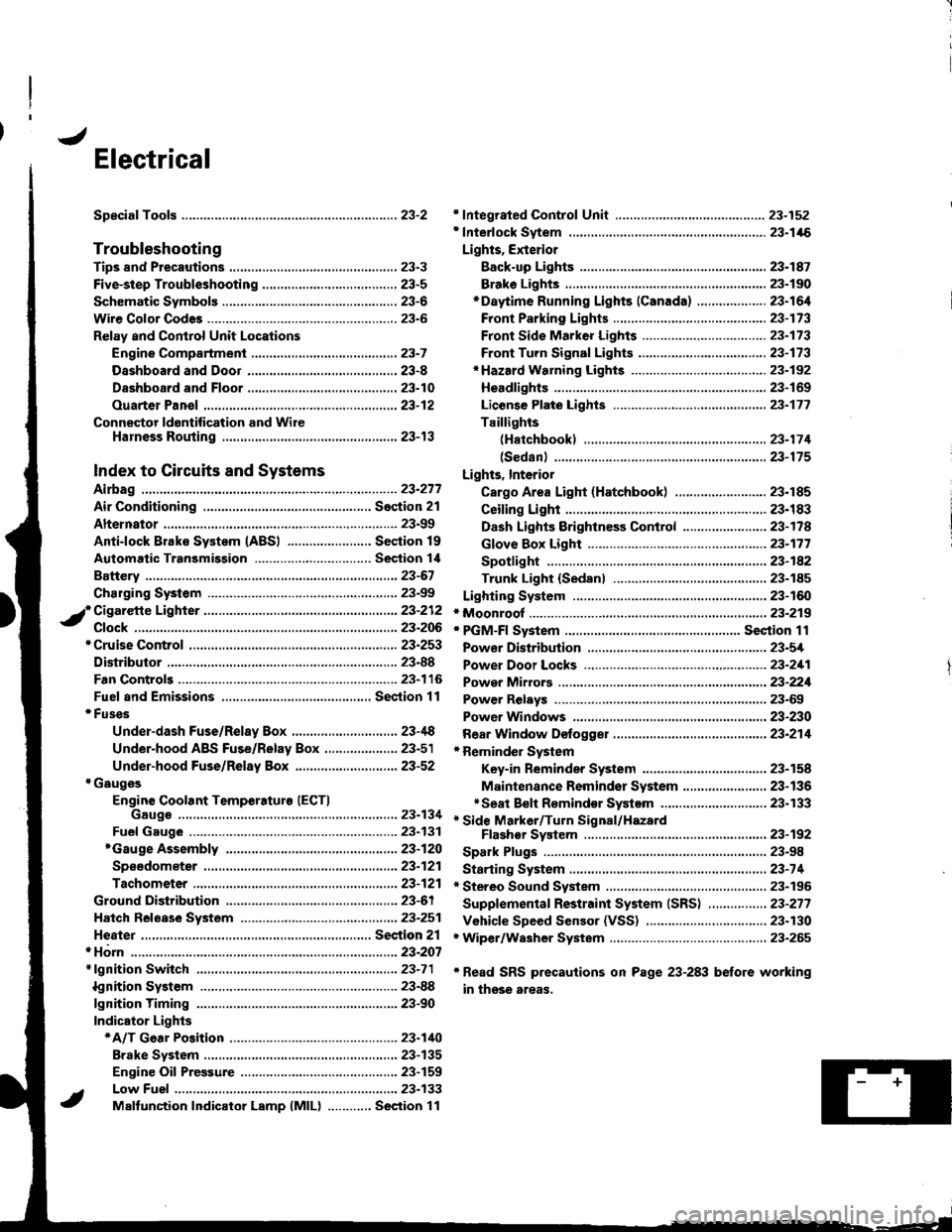
J
Electrical
Speciaf Toofs ..........................23-2
Troubleshooting
Tips 8nd Precautions .......................,..,.,.,.,.,......,..., 23-3
Five-step Troubleshooting ............,......,.,.,...,..,....., 23-5
Schsmatic Svmbols ...............23-6
Wire Color Code3 .. ................. 23-6
Relay and Control Unit Locations
Engine Compartment ......,.,.................,.,.,.,.,.,,,, 23-7
Dashboard and Door .........,...........,.....,.,....,.,.... 23-8
Dashboard and Floor ......................................... 23-10
Ouarter Pan€f .,,.,...,.,..,...,,,23-12
Connector ldontification and WireHarness Routing ......,.,......23-'13
Index to Circuits and Systems
Airbag
* Integrated Control Unit .....,.,.,.....23-152* Interlock Sytem .,...,.,...........,. 23.146
Lights, Exterior
Eack-up LighB ..................23.187
Brake Ligh$ ......................23-190*Daytime Running Lights (Canada) ................... 23"164
Front Parking Lights .......................................... 23-173
Front Side Marker Lights .................................. 23-173
Front Turn Signal Lights ..................-.......,...,.,. 23-173* Hazard Warning Lights ....................,........,....... 23-192
Headlights.....23-169
23-253 powerDistribution..................... 23-5/r
Air Conditioning.....,....... Soction 21
Alternator ..........,................... 23.99
iCigarette Lighter .........23-212
*Cruise Control
Distributor
'.'.,.'.'.,.'...,,,,.,''.'.,.',.'''.' 23.277
.............................. 23.88
................... 23-90lgnition Timing ......
Indicator Lights
Key-in Reminder System
Maintenance Reminder System*Seat Belt R€mindor System .,...........................* Side Marker/Turn Signal/HazardFlashcr Svstem .................23-192
Spark Plugs ............................23-98
Starting System .....................23-74* Stereo Sound System ...,......,..........,...,......,.,.,.,..,., 23-196
Supplemental Restraint System (SRS) ................ 23-277
Vshicle Speed Sensor (VSS) ................................. 23.130r Wiper/Washer System .........................................., 23-265
*Read SRS precautions on Psge 23-283 before working
in those areas,
23-154
23.136
23"133
Page 1077 of 1681
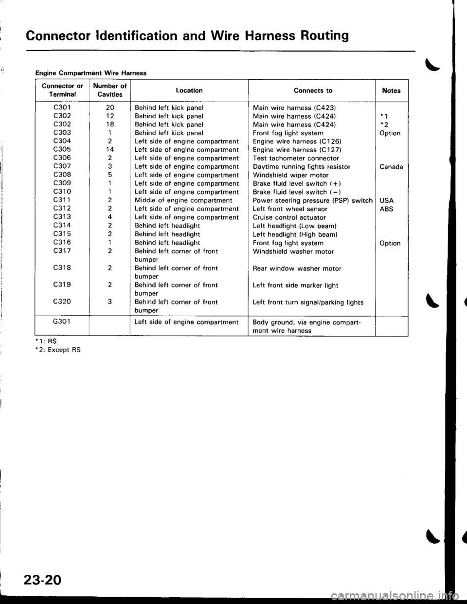
Connector ldentification and Wire Harness Routing
Engine Compartment Wire Halness
nll
Connectoa ot
Terminal
Number of
CavitiesLocationConnects toNotes
c301
c302
c 302
c303
c304
c306
c307
c308
c309
c310
c3l 1
c312
c314
c316
c317
c318
c319
c320
20
't8
1
14
2
3
5
1
1
2
2
4
2
2
1
2
2
2
3
Behind left kick panel
Behind left kick panel
Behind left kick panel
Behind left kick panel
Lett side of engine compartment
Lett side of engine companment
Lett side of engine compartment
Left side of engine compartment
Left side of engine compartment
Left side of engine compartment
Left side of engine compartment
Middle of engine compartment
Lett side of engine companment
Left side of engine compartment
Behind left headlight
Behind left headlight
Behind left headlight
Behind left corner of front
DUmper
Behind left corner ol front
bumper
Behind lett corner of front
bumper
Behind left co.ner of lront
bumper
Main wire harness (C423)
Main wire harness {C424)
N4ain wire harness (C424)
Front fog light system
Engine wire harness (C126)
Engine wire harness (C'127)
Test tachometer connector
Daytime running lights resistor
Windshield wiper motor
Brake f luid level switch (+ )
Brake f luid level switch ( - )
Power steering pressure (PSP) switch
Lett front wheel sensor
Cruise control actuator
LeIt headlight (Low beam)
Lett headlight {High beam)
Front fog light system
Windshield washer motor
Rear window washer motor
Left front side marker light
Left front turn signal/parking lights
Option
Canada
USA
ABS
Option
G301Lelt side of engine compartmentBody ground, via engine compart-
ment wire harness
23-20
Page 1079 of 1681
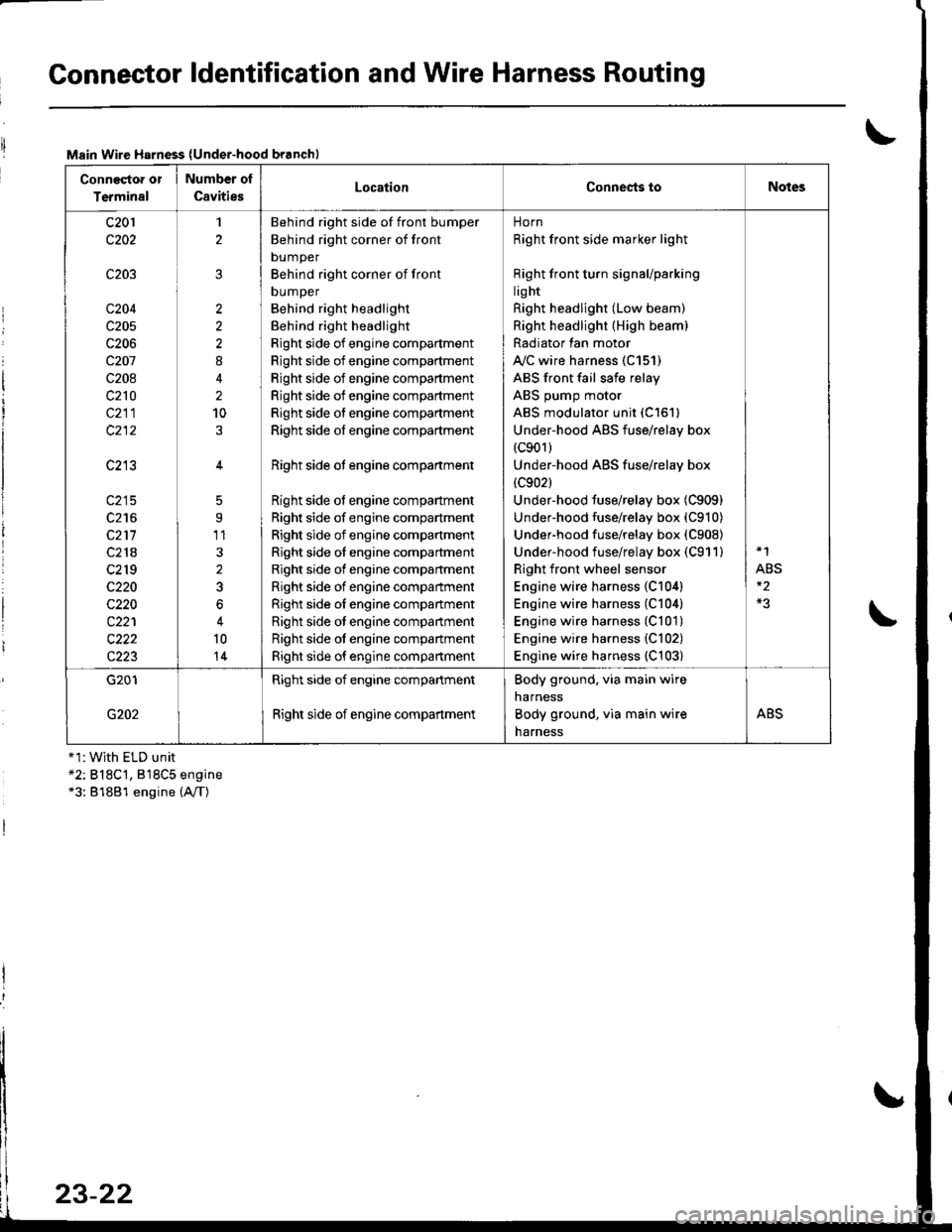
Connector ldentification and Wire Harness Routing
Main Wire Harness (Under-hood branchl
Conneqtor or
Terminal
Number ol
CavitiesLocationConnests toNotes
c201
c202
c203
c204
c205
c206
c207
c208
c210
c211
c213
c215
c216
c211
c218
c2r 9
c220
c220
c221
c222
c223
1
2
2
2
2
8
2
10
5
9'11
3
2
3
6
10
14
Behind right side of front bumper
Behind right corner of front
bumper
Behind right corner of front
DUmper
Behind right headlight
Behind right headlight
Right side of engine compartment
Right side of engine compartment
Right side of engine compartment
Right side of engine compartment
Right side of engine compartment
Right side of engine compartment
Right side ot engine compartment
Right side of engine compartment
Right side of engine compartment
Right side of engine compartment
Right side of engine compartment
Right side of engine compartment
Right side of engine compartment
Right side oI engine companment
Right side ot engine compartment
Right side ot engine compartment
Right side of engine compartment
norn
Right front side marker light
Right front turn signaUparking
lig ht
Right headlight (Low beam)
Right headlight (High beam)
Radiator lan motor
A"/C wire harness (C151)
ABS front fail safe relay
ABS pump motor
ABS modulator unit (C151)
Under-hood ABS fuse/relay box(c901)
Under-hood ABS fuse/relay box
{c902}
Under-hood fuse/relay box (C909)
Under-hood fuse/relay box (C910)
Underhood fuse/relay box (C908)
Under-hood fuse/relay box (C911)
Right front wheel sensor
Engine wire harness {C104)
Engine wire harness (C104)
Engine wire harness (C101)
Engine wire harness {C102)
Engine wire harness (C103)
*1
ABS
G201
G202
Right side of engine compartment
Right side of engine compartment
Body ground. via main wire
narness
Body ground, via main wire
harness
ABS
+1:With ELD unit*2: B18C't, 818C5 engine*3: 81881 engine (A,/T)
23-22
Page 1085 of 1681
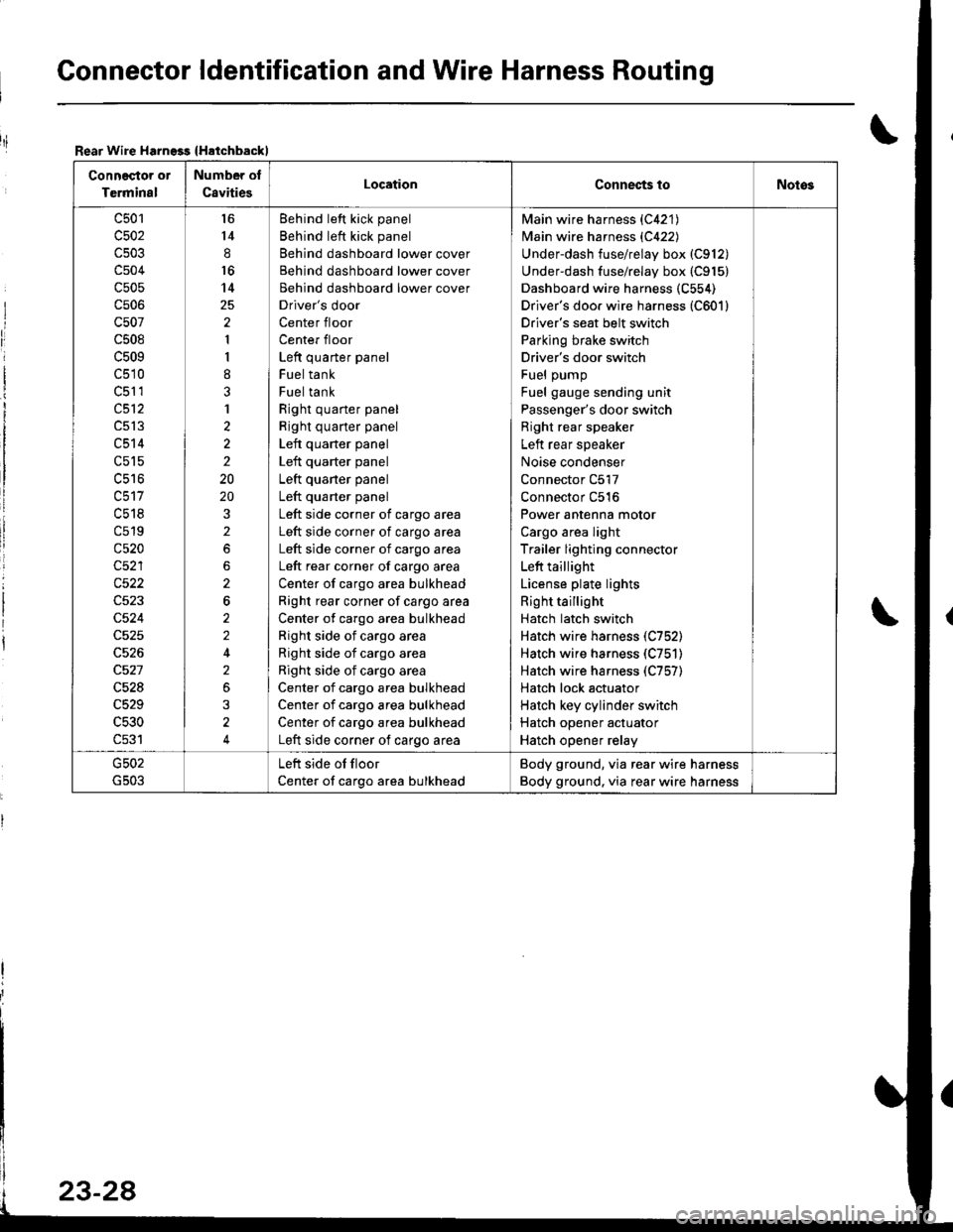
Gonnector ldentification and Wire Harness Routing
Rear Wire Harngss {Hatchbackl
Connector or
Terminal
Number of
C8vitiesLocationConnec{s toNotos
c501
c502
c504
c505
cs06
c507
c508
c509
c510
c51 1
c512
c513
c514
c515
uc to
c518
c519
c520
c522
c524
c528
c529
c530
c531
l6
14
8
16
14
2
1
I
8
3
1
2
2
2
20
20
2
2
6
2
2
2
3
4
Behind left kick panel
Behind left kick panel
Behind dashboard lower cover
Behind dashboard lower cover
Behind dashboard lower cover
Driver's door
Center floor
Center floor
Left quarter panel
Fuel tank
Fuel tank
Right quarter panel
Right quarter panel
Left quarter panel
Left quarter panel
Left quaner panel
Left quarter panel
Left side corner of cargo area
Left side corner of cargo area
Left side corner of cargo area
Left rear corner of cargo area
Center of cargo area bulkhead
Right rear corner of cargo area
Center of cargo area bulkhead
Right side of cargo area
Right side of cargo area
Right side of cargo area
Center of cargo area bulkhead
Center of cargo area bulkhead
Center of cargo area bulkhead
Left side corner of cargo area
Main wire harness {C421)
Main wire harness {C422)
Underdash fuse/relay box (C912)
Underdash fuse/relay box (C915)
Dashboard wire harness (C554)
Driver's doo. wire harness (C601)
Driver's seat belt switch
Parking brake switch
Driver's door switch
Fuel pump
Fuel gauge sending unit
Passenger's door switch
Right rear speaker
Left rear speaker
Noise condenser
Connector C517
Connector C516
Power antenna motor
Cargo area light
Trailer lighting connector
Left taillight
License plate lights
Right taillight
Hatch latch switch
Hatch wire harness (C752)
Hatch wire harness (C751)
Hatch wire harness (C757)
Hatch lock actuator
Hatch key cylinder switch
Hatch opener actuator
Hatch opener relay
Left side of floor
Center of cargo area bulkhead
Body ground, via rear wire harness
Body ground. via rear wire harness
riI