Head HONDA INTEGRA 1998 4.G Service Manual
[x] Cancel search | Manufacturer: HONDA, Model Year: 1998, Model line: INTEGRA, Model: HONDA INTEGRA 1998 4.GPages: 1681, PDF Size: 54.22 MB
Page 765 of 1681
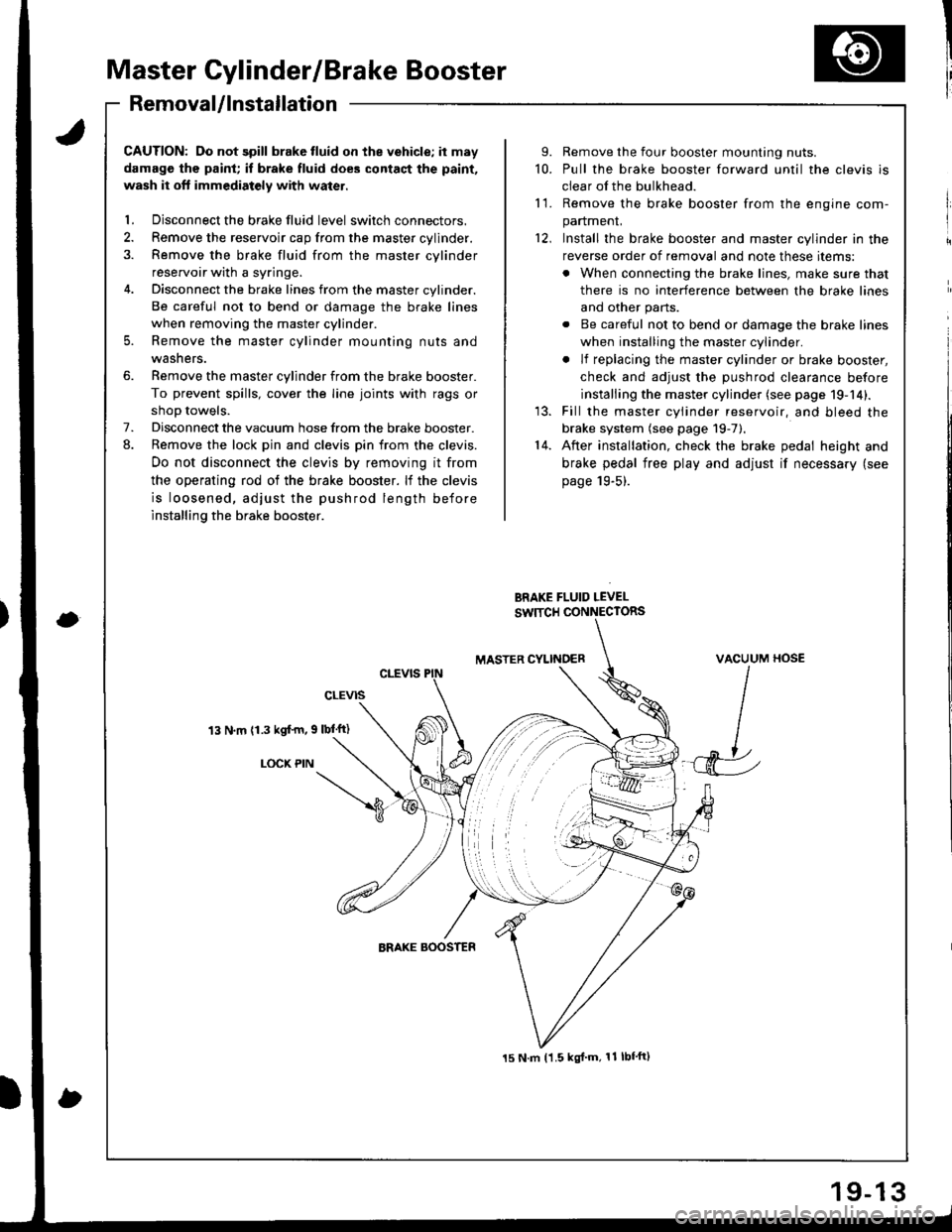
Master Cylinder/Brake Booster
I'RemovaUlnstallation
CAUTION: Do not spill brake tluid on the vehicle; it may
damage the paint; if brake fluid does contact the paint,
wash it oft immediatoly with water.
l. Disconnect the brake fluid level switch connectors.
2. Remove the reservoir cap from the master cylinder.
3. Remove the brake fluid from the master cvlinder
reservoir with a syringe.
4. Disconnect the brake lines from the master cylinder.
Be careful not to bend or damage the brake lines
when removing the master cylinder.
5. Remove the master cylinder mounting nuts and
washers.
6. Remove the master cylinder from the brake booster.
To prevent spills, cover the line joints with rags or
shoD towels.
7. Disconnect the vacuum hose from the brake booster.
8. Remove the lock pin and clevis pin from the clevis.
Do not disconnect the clevis by removing it from
the operating rod of the brake booster. lf the clevis
is loosened, adjust the pushrod length before
installing the brake booster.
13 N.m (1.3 kgf'm, 9 lbl'ft)
LOCX PIN
9. Remove the four booster mounting nuts.
10. Pull the brake booster forward until the clevis is
clear of the bulkhead.
11. Remove the brake booster from the enqine com-
panmenL
12, Install the brake booster and master cylinder in the
reverse order of removal and note these items:
. When connecting the brake lines, make sure that
there is no interference between the brake lines
and other parts.
. Be careful not to bend or damage the brake lines
when installing the master cylinder.
. lf replacing the master cylinder or brake booster,
check and adiust the DUshrod clearance before
installing the master cylinder (see page 19-14).
13. Fill the master cylinder reservoir, and bleed the
brake system (see page 19-7).'14. After installation, check the brake pedal height and
brake pedal free play and adjust if necessary (see
page 19-5).
BRAKE FLUID LEVEL
SW]TCH CONNECTORS
MASTER CYLINOERVACUUM HOSE
J
15 N.m t1.5 kgl'm, 11 lbf'ft)
Page 816 of 1681
!
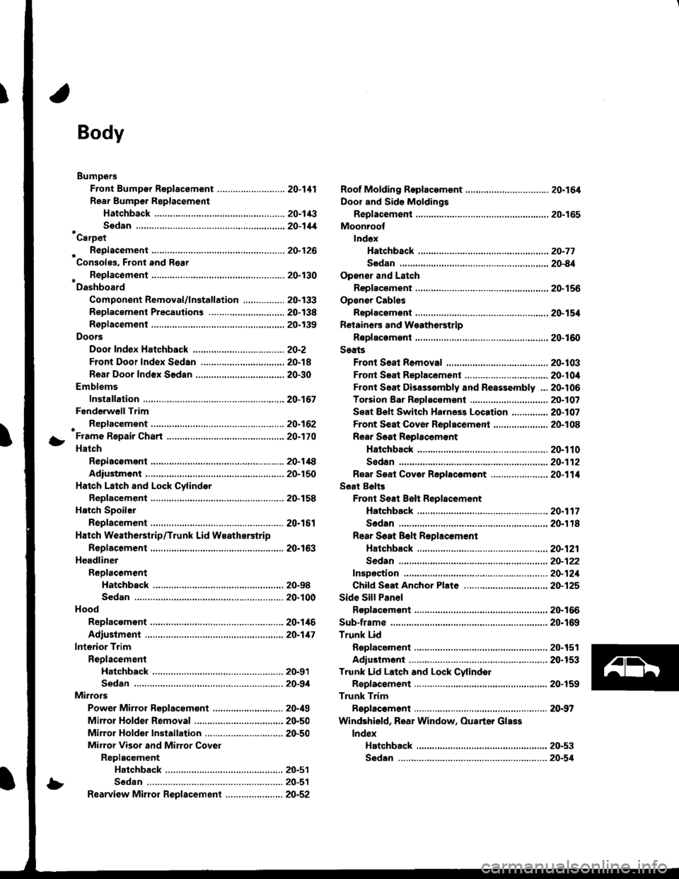
Body
Bumpers
Front Bumper Replacement ....................-..... 20-111
Rear Bumpar Replacemeni
Hatchback ................. 20-1/B
Sedan .................... ....20-111'Carpet
. Repfacemenl .,.,.,.,,..-....-.20-126
Consoles, Front and Rear
* Replacement ..................20-130
Dashboard
Component Removal/lnstallation ................ 20-133
Replacement Precautions ...........,................. 20-138
R€placement ....,.,...........20-139
Doors
Door Index Hatchback ................................... 20-2
Front Door Index Sedan .................,.,..,.,....,.. 20-18
Rear Door Index Sedan ........,.,........,.............. 20-30
Emblems
Installation .....................20-167
FenderwellTrim
+ Replacement., ................20.162
Fram€ Repair Chart .-..........20-170
Hatch
Replacoment .......,..........20-118
Adiustment .................... 20-150
Hatch Latch and Lock Cylinder
Replacement ..,.,..... ........ 20-158
Hstch Spoiler
Replacement ......... .......-.20.161
Hatch Weatherstrip/Trunk Lid Wsatherstrip
Replacement ..................20.163
Headliner
ReDlacement
Hatchbsck ,.,....,......,.. 20-98
Sedan .........................................................20-100
Hood
Replacsment ......... ......... 20.146
Adiustment ....................20-117
lnterior Trim
Reolacement
Hatchback ................. 20-91
Sedan .........................................................20-9,1
Mirrors
Power Mirror Reolacement ..........,................ 20-49
Mirrol Holder Removal ............................,..... 20.50
Mirror Holder Installation .............................. 20-50
Mirror Visor and Mirrot Covet
Replacement
Haichback ............20-51
Sedan .................................................... 20-51
Rearview Mirror Reolacement ..........-....-.-.... 20.52
Roof Molding Rep|acament ................................ 20.164
Door and Sid€ Moldings
Replacement .,..........,..... 20-165
Moonroot
lnd6x
Hatchback -................20-77
Sodan .........................................................20-8il
Opener and Latch
Replacement .......... ......,. 20-156
Opensr Cables
Replacamsnt .,.,...,.. ......., 20-154
Retainers and W€atherstrip
Replacement .................. 20-160
Seats
Front Seat Romoval ....................................... 20-103
Front Seat Replacement ...........................,.,.. 20-104
Front Soat Disassembly and Reassembly ...20-106
Torsion Bar ReDlacomant .....,...,......,.......,..,., 2O-1O7
Seat Eelt Switch Ha.ness Location ..,...,.,.,..,2O-1O7
Front Seat Cover Replacemont ..,....,..,..,.....,. 20-108
Rear Soat Roplscemont
Hatchback ................. 20.110
Sedan.........................................................20-112
R€al Seat Cover Replacomont ...................... 20-114
Seat Belts
Front Seat Beh Replacement
Hatchback..................20.117
Sedan20-r18
Rear S6at Bolt R€plac€ment
Hatchback .-......-.-......20-121
Sedan.......................-.-....-.-..........-.............20-122
fnspection ......-.-.,....-.-....20-121
Chifd Seat Anchor Plate ................................ 20-125
Side Sill Panol
Beplacom€nt .................. 20-166
Sub-frame ........................... 20.169
Trunk Lid
Replacement ......... ..,..,.,.20-151
Adiustmeni .................... 20-153
Trunk Lid Latch and Lock Cvlindot
Replac€ment ......... ......... 20-159
Trunk Trim
Replacement .,.,,.,........... 20-97
Windshield, Rear Window, Ouarter Glass
lndex
Hatchback ...........,,.20-53
!
S6dan ......................................................... 20.54
Page 870 of 1681
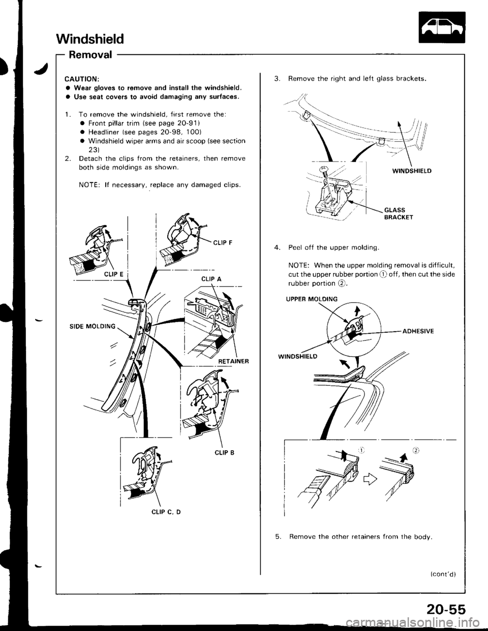
Windshield
Removal
CAUTION:
a Wear gloves to remove and inslall the windshield,
a Use seat covers to avoid damaging any surtaces.
1. To remove the windshield, Jirst remove the:
a Front pillar trim (see page 2O-91)
. Headliner (see pages 20-98, 1O0)
a Windshield wiper arms and air scoop (see section
231
2. Detach the clips from the retainers, then remove
both side moldings as shown.
NOTE: lf necessary, replace any damaged clips.
3. Remove the right and left glass brackets.
WINOSHIELD
Peel off the upper molding.
NOTE: When the upper molding removal is dillicult,
cut the upper rubber portion O off, then cut the side
rubber portion @.
UPPER MOLDING
ADHESIVE
WINDSHIELD
5. Remove the other retainers from the bodv.
CLIP C, D
(cont'd )
Page 883 of 1681
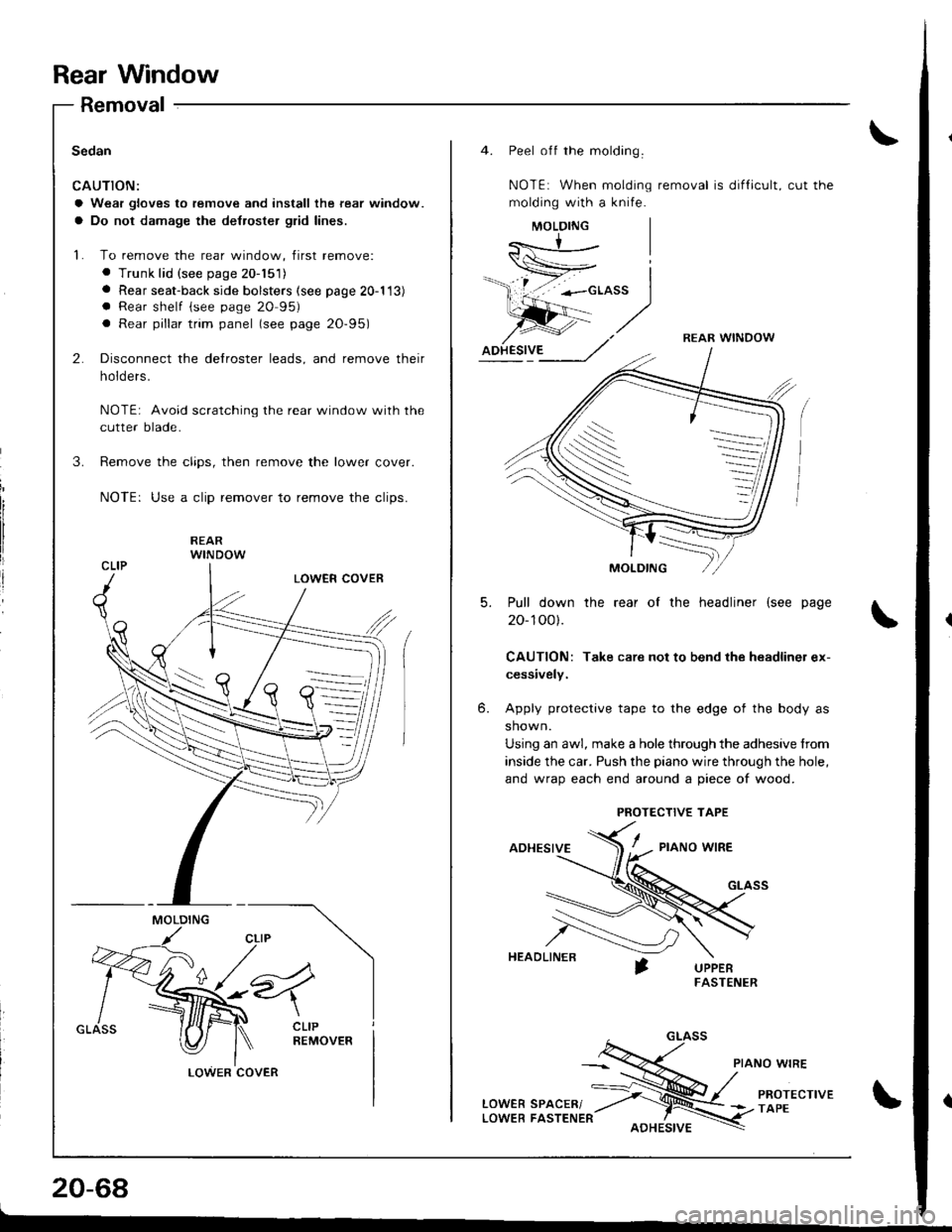
Rear Window
Removal
Sedan
CAUTION:
a Wear gloves to remove and install the rear window.
a Do not damage the de{roster glid lines.
L To remove the rear window, first remove:
. Trunk lid (see page 20-151)a Rear seat-back side bolsters (see page 20-113)a Rear shelf (see page 20 95)
a Rear pillar trim panel (see page 20-95)
2.
3.
Disconnect the delroster leads, and remove their
holders.
NOTE: Avoid scratching the rear window with the
cutter blade.
Remove the clips, then remove the lower cover.
NOTE: Use a clip remover to remove the clips.
_\--n _/i<.-,|
MOLDING
v"4
\CLIPREMOVER
LOWERCOVER
20-68
L
4. Peel off the molding.
NOTEi When molding removal is dif{icult, cut the
molding with a knife.
REAR WINDOW
S
-
5.Pull down
20- 100).
CAUTION:
cessively.
the rear of the headliner (see page
Take care not to bend the headliner ex-
6.Apply protective tape to the edge of the body as
shown.
Using an awl, make a hole through the adhesive from
inside the car. Push the piano wire through the hole,
and wrao each end around a oiece of wood.
ADHESIVE/ - ,,o"o *,aa
HEAOLINER
PROTECTIVE TAPE
Page 894 of 1681
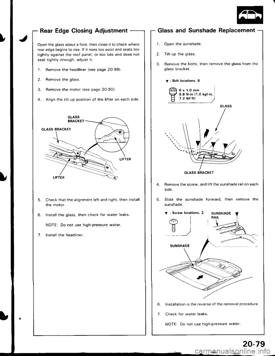
Rear Edge Closing Adjustment
Open the glass about a foot, then close it to check where
rear edge begins to rise. lf it rises too soon and seats too
tightly against the roof panel, or too late and does not
seat tightly enough, adjust it.
'l . Remove the headliner (see page 2O-98).
2. Remove the glass.
3. Remove the motor (see page 2O-80).
4. Align the tilt up position of the lifter on each side.
Check that the alignment le,ft and right, then install
the motor.
Install the glass, then check for water leaks.
NOTE: Do not use high-pressure water.
Install the headliner.
1.
2.
3.
Glass and Sunshade Replacement
Open the sunshade.
Tilt up the glass.
Remove the bolts, then remove the glass from the
glass bracket.
V : Bolt localions, 6
GLASS
t
4. Remove the screw, and lift the sunshade railon each
srcle.
5. Slide the sunshade torward, then remove the
sunshade.
v : Screw locations, 2
I
I
i
6x1.0mm l9.8 N.m {1.O kgt.m,l7.2 tbt.ftt )
Installation is the reverse of the removal procedure-
Check for water leaks.
NOTE: Do not use high-pressure water.
GLASS BRACKET
20-79
Page 895 of 1681
Moonroof
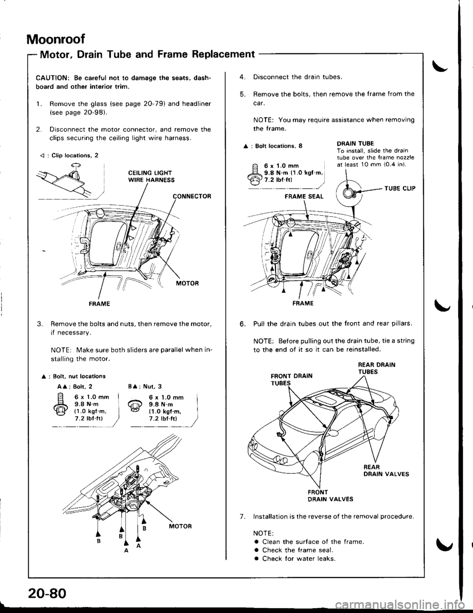
Motor, Drain Tube and Frame Replacement
CAUTION: Be careful not to damage the seats, dash-
boa.d and other interior trim.
1. Remove the glass (see page 20-79) and headliner
{see page 2O-98}.
2. Disconnect the motor connector, and remove the
clips securing the ceiling light wire harness.
Remove the bolts and nuts, then remove the motor,
if necessary.
NOTE: Make sure both sliders are parallel when in-
stalling the motor.
3.
: Bolt, nut locations
A
: 8olt, 2
6x 1.0mm I9.8Nm L
Nut, 3
6 x 1.0 mm I9.4 N.m
BA:
6@{1.0 kgf7 .2 tbl:!)(1.O kgf m, I
1'�lIltl /
< : Clip locations, 2
4,
FRAME
Oisconnect the drain tubes.
Remove the bolts, then remove the lrame from the
car.
NOTE: You may require assistance when removing
the trame.
A : Bolt locations, 8
TUBE CLIP
FRAME SEAL
Pull the drain tubes out the front and rear pillars.
NOTE: Before pulling out the drain tube, tie a string
to the end of it so it can be reinstalled.
REAR DRAINTUBES
7. Installation is lhe reverse of the removal procedure.
NOTE:
a Clean the surtace of the frame.
a Check the lrame seal.
a Check tor water leaks.
DRAIN TUBETo install, slide the draintube over the {rame nozzleat least 10 mm i0.4 in).
-'
6 x 1.0 mm9.8 N.m 11.0 kgt m,7.2 tbf.fr)
FRAME
FRONTDRAIN VALVES
!
\"
20-80
\
v
Page 901 of 1681
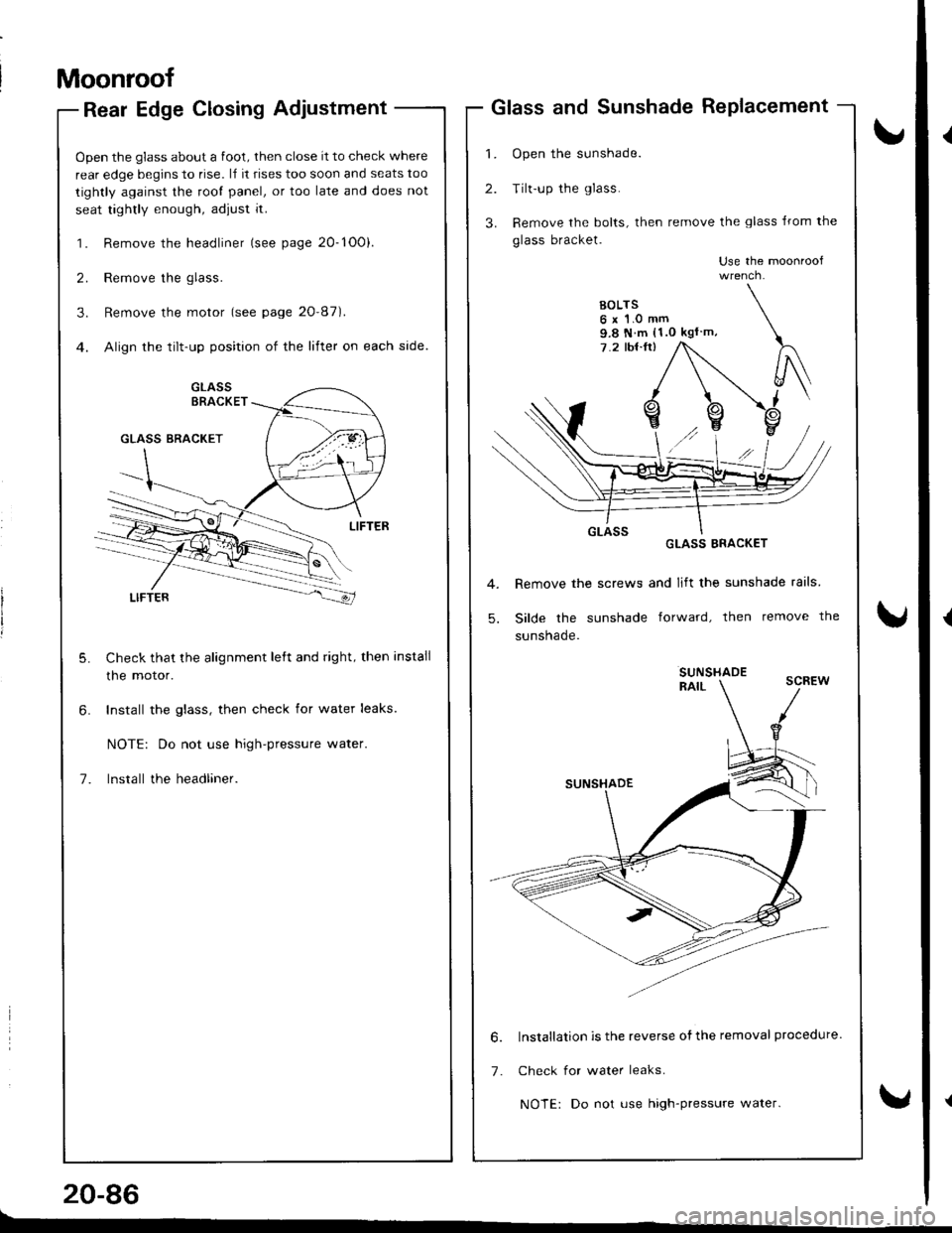
Moonroof
Rear Edge Closing Adjustment
Open the glass about a foot, then close it to check where
rear edge begins to rise. l,f it rises too soon and seats too
tightly against the root panel, or too late and does not
seat tightly enough, adjust it.
1. Remove the headliner (see page 20-1O0).
2. Remove the glass.
3. Remove the motor (see page 20'87).
4. Align the tilt-up position of the lifter on each side.
Check that the alignment left and right, then install
the motor.
Install the glass, then check for water leaks.
NOTE: Do not use high-pressure water.
lnstall the headliner.
20-86
Glass and Sunshade RePlacement
1. Open the sunshade.
2. Tilt-up the glass.
3. Remove the bolts, then remove the glass lrom the
glass bracket.
Use the moonroof
GLASS ERACKET
Remove the screws and lift the sunshade rails
Silde the sunshade forward, then remove the
sunsnaqe.
SUNSHADERAIL
lnstallation is the reverse ofthe removal procedure.
Check for water leaks.
NOTE: Do not use high-pressure water.
9.8 N m (1.0 kgl m,
6.
7.
Page 902 of 1681
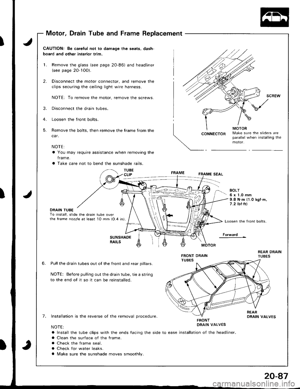
Motor, Drain Tube and Frame Replacement
J
J
CAUTION: Be ca.eful not to damage the seats, dash-
board and other interior trim,
1. Remove the glass (see page 2O-86) and headliner(see page 20- 1OO).
2. Disconnect the motor connector, and remove the
clips securing the ceiling light wire harness.
NOTE: To remove the motor, remove the screws.
3. Disconnect the drain tubes.
4. Loosen the front bolts.
5. Remove the bolts, then remove the frame from the
car.
NOTE:
a You may require assistance when removing the
f rame.
a Take care not to bend the sunshade rails.
TUBECLIP
CONNECTORMake sure the sliders areparallel when installing themotor.
FRAMEFRAME SEAL
DRAIN TUBETo Install, slide the drain tube overthe frame nozzle at least 10 mm (0.4 in).
EOLT6 x 1.0 mm9.8 N.m l1.O kgf .m,
7 .2 tbt.ltl
Loosen the front bolts,
Fo.ward
6.
7.
SUNSHADERAILS
Pull the drain tubes out of the front and rear pillars.
NOTE: Before pulling out the drain tube, rie a string
to the end oI it so it can be reinstalled.
Installation is the reverse ol the removal procedure.
NOTE:
a Install the tube clips with the ends {acing the side to ease
a Clean the surface of the frame.
a Check the frame seal.
a Check lor water leaks.
a Make sure the sunshade moves smoothly.
FRONTDRAIN VALVES
installation of the headliner.
Page 913 of 1681
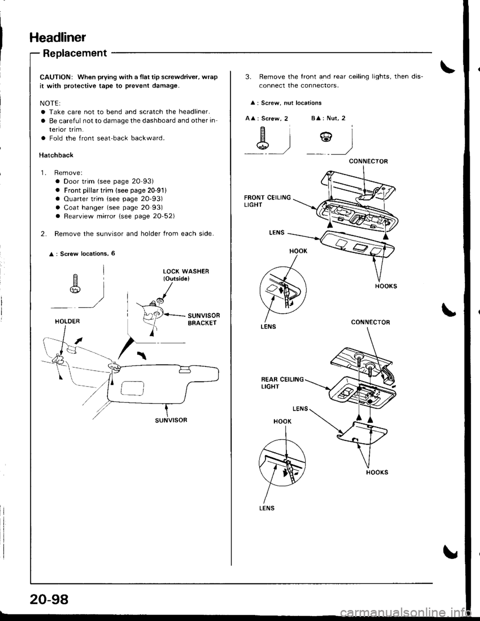
Headliner
Replacement
CAUTION: When prying with a llat tip screwdriver. wrap
it with protective tape to prevent damage.
NOTE:
a Take care not to bend and scratch the headliner.
a Be careful not to damage the dashboard and other in
renor rr|m.
a Fold the front seat-back backward.
Hatchback
1. Remove:
a Door trim (see page 20-93)
. Front pillar trim (see page 20-91)
a Ouarter trim (see page 20-93)
a Coat hanger (see page 20 93)
a Rearview mirror (see page 20-52\
2. Remove the sunvisor and holder from each side.
: Sc.ew locations, 6
^l
r$,,
)
LOCK WASHER(o{rtsid€}
^cl
H
A2P-suNvlsoR
)
ERACKErHOLOER
20-98
3. Remove the lront and rear ceiling lights, then dis-
connect the connectors.
: Screw, nut locations
A : Screw, 2B : Nut, 2
\g .)Y)
HOOK
)
(s)
V AI ./
LENS
HOOK
A
N)
YLENS
CONNECTOR
CONNECTOR
Page 914 of 1681
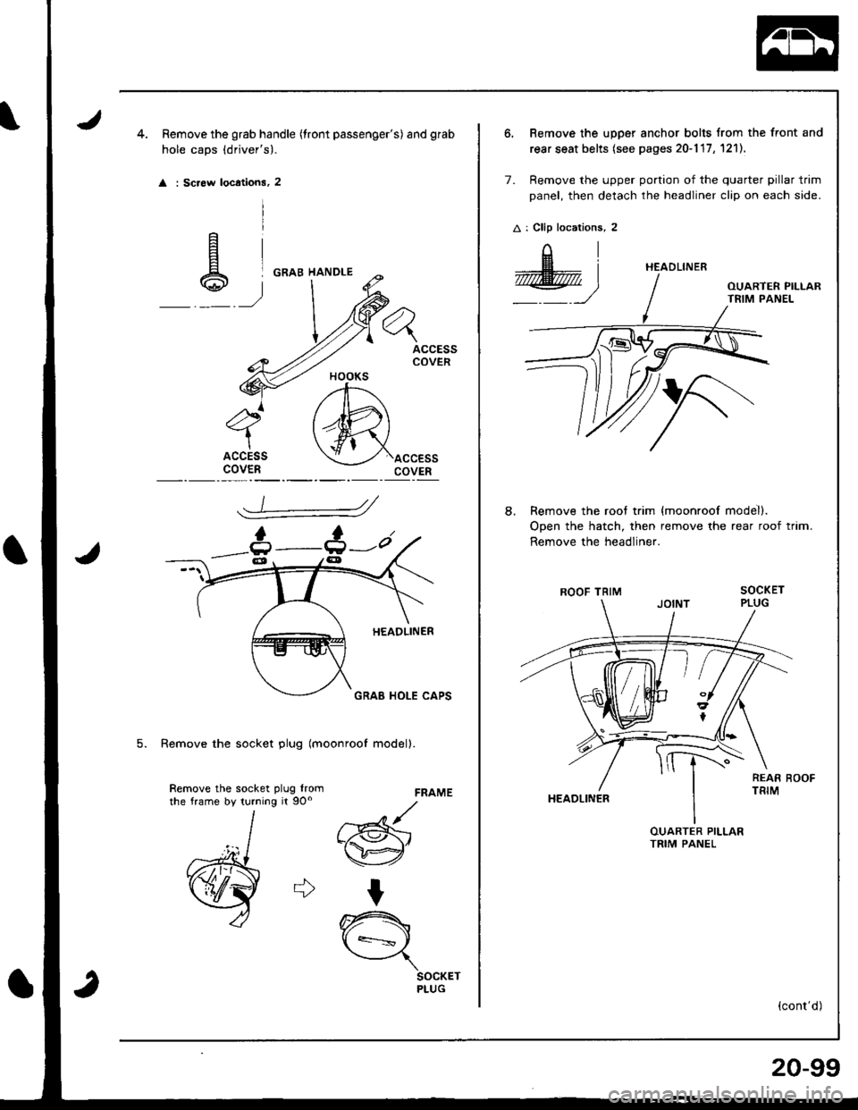
Remove the grab handle (tront passenger's) and gfab
hole caps (drjver's).
: Screw locations, 2
ACCESSCOVER
ACCESScovEnaccEssCOVER
FRAME
d
w"
t
A
\={
SOCKETPLUG
5. Remove the socket plug lmoonroof modell.
Remove the socket plug lromrhe frame by turning it 9Oo
6. Remove the upper anchor bolts from the front and
rear seat belts (see pages 20-117 , 1211.
7. Remove the upper portion of the quarter pillar trim
panel, then detach the headliner clip on each side.
A : Clip locations, 2
AI
@)
Remove the roof trim
Open the hatch, then
Remove the headliner.
ROOF TRIM
HEAOLINER
{moonroof model).
remove the rear roof trim.
(cont'd)
HEADLINER
8.
20-99