Head HONDA INTEGRA 1998 4.G Owner's Guide
[x] Cancel search | Manufacturer: HONDA, Model Year: 1998, Model line: INTEGRA, Model: HONDA INTEGRA 1998 4.GPages: 1681, PDF Size: 54.22 MB
Page 343 of 1681
t"iI
Emission Gontrol System
System Description
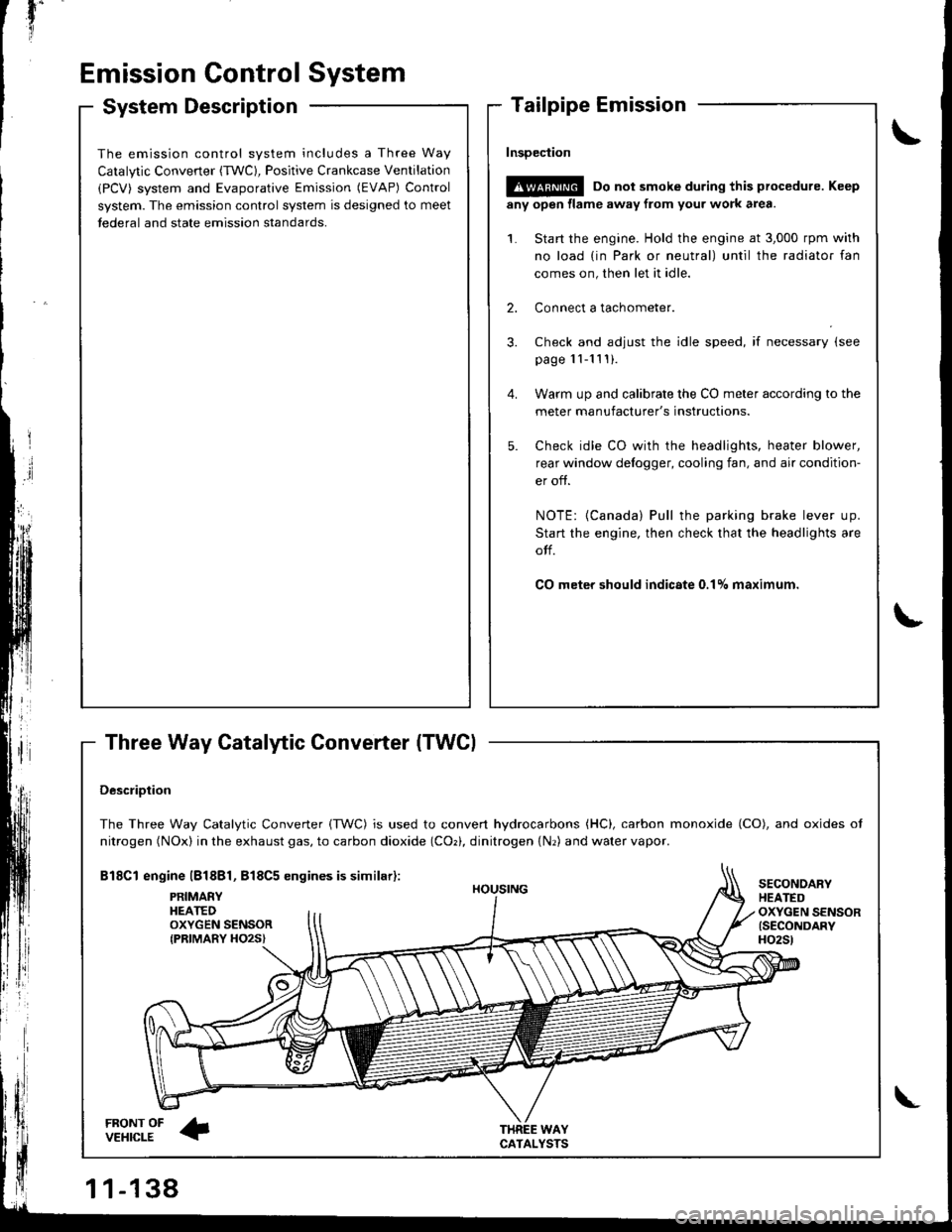
Three Way Catalytic Converter (TWCI
\
t
The emission control system includes a Three Way
Catalytic Converter (TWC), Positive Crankcase Ventilation
(PCV) system and Evaporative Emission (EVAP) Control
system. The emission control system is designed to meet
tederal and state emission standards.
InsDeciion
!@@ Do not smoke during this procedure. Keep
any open llame away from your work area.
1. Start the engine. Hold the engine at 3,000 rpm with
no load {in Park or neutral) until the radiator fan
comes on, then let it idle.
2. Connect a tachometer.
Check and adjust the idle speed, if necessary (see
page '11-11 ! ).
Warm up and calibrate the CO meter according to the
meter manufacturer's instructions.
Check idle CO with rhe headlights, heater blower,
rear window defogger, cooling fan, and air condition-
er off.
NOTE: {Canada) Pull the parking brake lever up.
Start the engine, then check that the headlights are
olf.
CO meter should indicste 0.17o maximum.
DescriDtion
The Three Way Catalytic Converter {TWC) is used to convert hydrocarbons (HC), carbon monoxide (CO), and oxides of
nitrogen (NOx) in the exhaust gas, to carbon dioxide (COr), dinitrogen {Nr) and water vapor.
Bl8Cl engine l818Bl, 818C5 engines is similar):
FRONT OFVEHICLE
PRIMAEYHEATEDOXYGEN SENSORIPRIMARY HO2S}
HOUSING
WAYCATALYSTS
SECONOARYHEATEDOXYGEN SENSOR{SECONDARYH02St
\
Page 403 of 1681
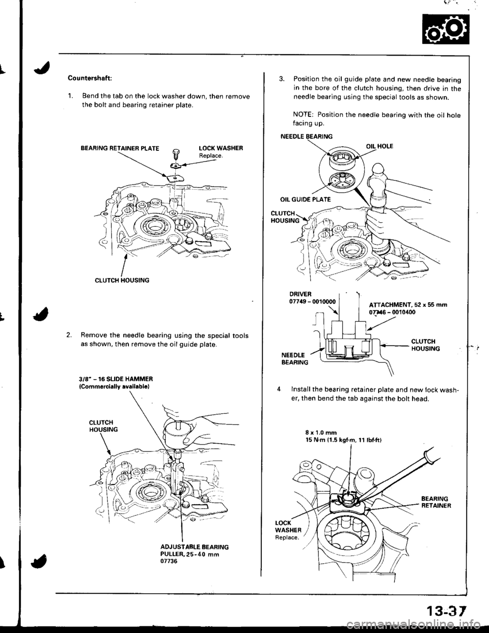
Countershaft:
1. Bend the tab on the lock washer down, then remove
the bolt and bearing retainer plate.
CLUTCH
;:-
2.Remove the needle bearing using the special
as shown, then remove the oil guide plate.
3/8- - 16 SLIDE HAMMER
lcommercially .vailablel
tools
ADJUSIABLE BEARINGPULLER,25-40 mm07736
3. Position the oil guide plate and new needle bearing
in the bore of the clutch housing, then drive in theneedle bearing using the special tools as shown.
NOTE: Position the needle bearing with the oil holefacing up.
NEEDLE
OIL HOLE
OIL GUIDE PLATE
CLUTCHHOUSING
lnstall the bearing retainer plate and new lock wash-
er, then bend the tab against the bolt head.
8x1.0mm15 N.m 11.5 kgf.m, 11 lbtftl
LOCKWASHERReplace.
ATTACHMENT, 52 x 5s mm
13€r
Page 579 of 1681
![HONDA INTEGRA 1998 4.G Owners Guide 18. Install the sub-shaft assembly in the transmission
housing {see page 14-142],.
19. Install the reverse idler gear and gear shaft holder(see page 14-158).
20. Install the differential assembly in HONDA INTEGRA 1998 4.G Owners Guide 18. Install the sub-shaft assembly in the transmission
housing {see page 14-142],.
19. Install the reverse idler gear and gear shaft holder(see page 14-158).
20. Install the differential assembly in](/img/13/6069/w960_6069-578.png)
18. Install the sub-shaft assembly in the transmission
housing {see page 14-142],.
'19. Install the reverse idler gear and gear shaft holder(see page 14-158).
20. Install the differential assembly in the torque con
verter housrng.
21. Assemble the mainshaft and countershaft sub-
assembly, then install them together in the torque
converler noustng.
22. Turn the shilt fork so the large chamlered hole is fac-
ing the fork bolt hole, then installthe shift tork with
the reverse selector and torque the lock bolt. Bend
the lock tab against the bolt head.
SHIFT FORK
23. Install the reverse gear with the collar and needte
bearing on the countershaft.
24. Align the spring pin of the control shaft with the
transmission housing groove by turning the control
shaft.
25. Place the transmission housing on the torque con-
verter housing with a new gasket and the three
dowel pins.
CONTROL
TRANSMISSION HOUSING
lnstall the transmission housing mounting bolts along
with the transmission hanger and the connector
bracket, then torque the bolts in two or more steps
in the sequence shown.
TOROUE: rt4 N'm (4.5 kgt.m, 33 lbt.lt)
TRANSMISSION
26.
LOCK WASHERReplace.
6 x 1.0 mm4 t{.m(1.4 kgf.m, 10
e
Large chamfered hole
/ -'K\,,
a
14-163
Page 658 of 1681
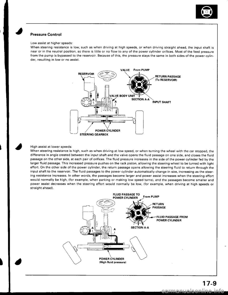
INPUT SHAFT
High assist at lower speedsl
When steering resistance is high, such as when driving at low speed, or when turning the wheel with the car stopped, the
diiference in angle created between the input shaft and the valve opens the tluid passage on one side, and closes the fluidpassage on the other side, at each pair of orifices. The fluid pressure lncreases in the side of the power cylinder fed by thelarger fluid passage. This increased pressure pushes on the rack piston, allowing the steering wheel to be turned with light
effon. On the other side of the power cylinder, the return passage opens allowing the steering fluid to return through theinput shaft to the reservoir. The fluid passages to the power cylinder automatically change in size, increasing as the steer-ing resistance increases. In other words, the passages become larger and power assist increases when the steering effort
would normally be high, (for example, when parking or making low speed turns), and the passages become smaller andpower assist decreases when the steering effort would normally be low, (for example, when driving at high speeds or
straight ahead).
FLUIO PASSAGE TOPOWER CYLINDER
Ce) r.r;
VK
Pressure Control
Low assist at higher speedsl
When steering resistance is low, such as when driving at high speeds, or when driving straight ahead. the lnput shaft is
near or in the neutral position, so there is liftle or no flow to any of the power cylinder orifices. Most of the feed pressure
from the pump is bypassed to the reservoir. Because of this, the pressure stays the same in both sides of the power cvlin-
der, resulting in low or no assist.
RETURN PASSAGE{To RESERVOIR)
POWER CYLINDERlHigh fluid pressurelI
ALVE FTom PUMP
RESERVOIR
SECTION A-A
17-9
Page 667 of 1681
Inspection and Adjustment
Steering Operation
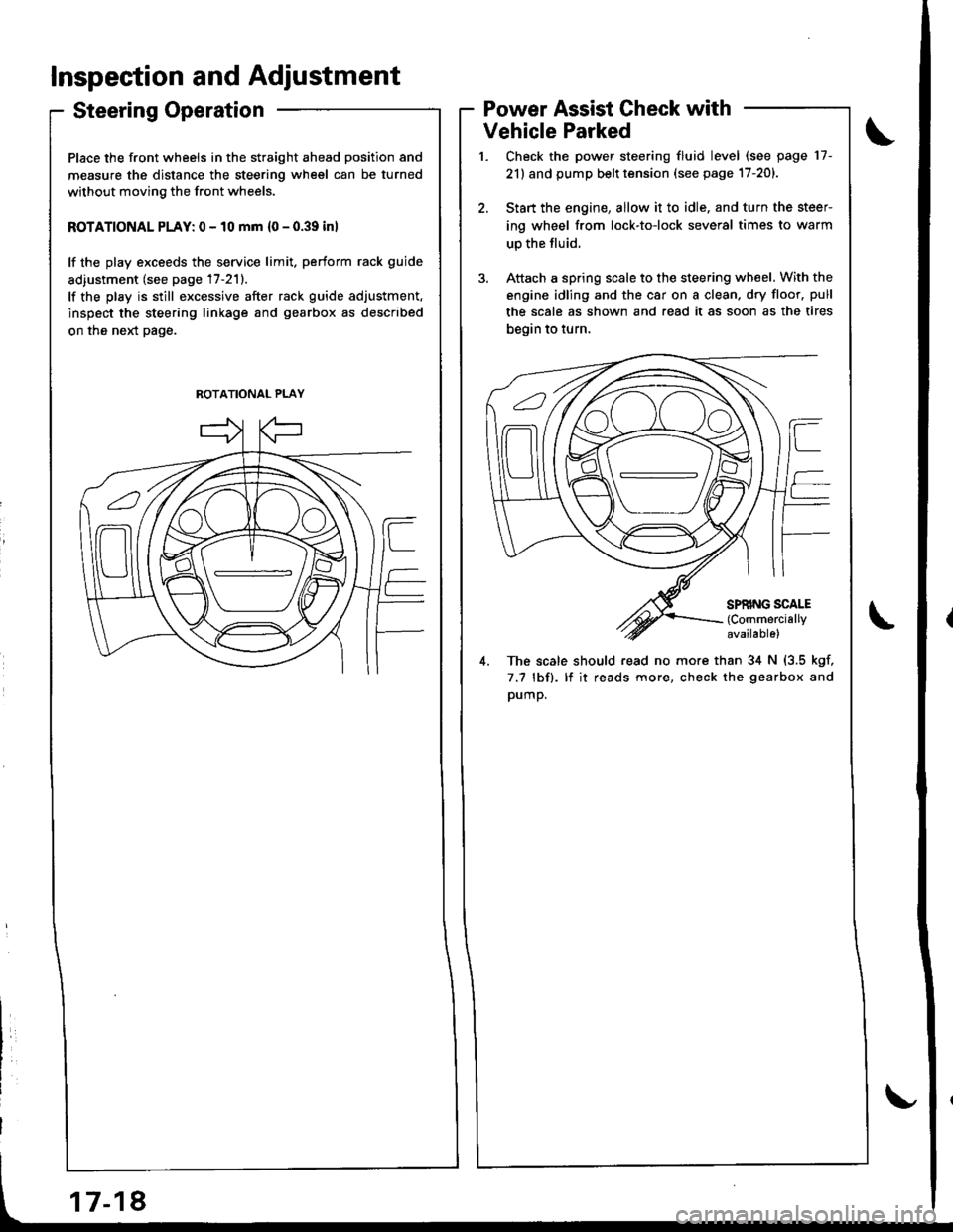
Place the front wheels in the straight ahead position and
measure the distance the steering wheel can be turned
without moving the front wheels.
ROTATIONAL PLAY: 0 - 10 mm {0 - 0.39 inl
lf the play exceeds the service limit. perform rack guide
adiustment (see page 17-211.
lf the play is still excessive after rack guide adjustment.
inspect the steering linkage and gearbox as described
on the neld page.
Power Assist Check with
Vehicle Parked
Check the power steering fluid level (see page 17-
21) and pump belt tension (see page 17-201.
Start the engine, allow it to idle. and turn the steer
ing wheel from lock-to-lock several times to warm
up the fluid.
Attach a spring scale to the steering wheel. With the
engine idling and the car on a clean. dry floor. pull
the scale as shown and read it as soon as the tires
begin to turn,
4. The scale should read no more than 34 N (3.5 kgf,
7.7 lbf). lf it reads more, check the gearbox and
pump.
ROTATIONAL PLAY
Page 670 of 1681
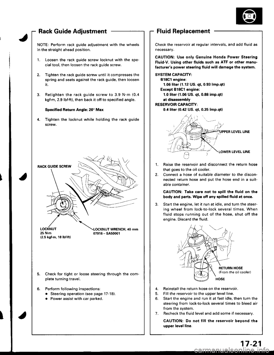
Rack Guide AdjustmentFluid Replacement
Check the reservoir at regular intervals, and add fluid as
neceSsary.
CAUTION: Use only Genuine Honda Powel Ste€ring
Fluid-V. Using other fluids such as ATF or othor manu-
laclurer's power ste€ring fluid will damag€ the systom.
SYSTEM CAPACIW:
B18Gl ongine:
1.06lit€r (1.12 US. qt,0.93 lmp.qt)
Excopt 8l8Cl ongino:
1.0 lher (r.06 US. qt.0.88 imp.qtl
at disa$ombly
RESERVOIR CAPACITY:
0.,0 liter {0.42 US. qt, 0.35 lmp.qt}
LEVEL LINE
LEVEL LINE
Raise the reservoir and disconnect the return hose
that goes to the oil cooler.
Connect a hose of suitable diameter to the discon-
nected return hose and put the hose end in a suit-
able container.
CAUTION: Take care not to spill thq fluid on lhe
body and parts. Wipe off any spilled fluid al onc€.
Start the engine. let it run at idle, and turn the steer-
ing wheel from lock-to-lock several times. When
fluid stops running out of the hose, shut off the
engine. Discard the fluid.
2.
RETURN HOSE{From the oilcooler)
4. Reinstallthe return hose on the reservoir.
5. Fill the reservoir to the uDDer level line.
6. Start the engine and run it at fast idle, then turn the
steering from lock-to-lock several times to bleed air
from the system,
7. Recheck the fluid level and add some it necessary.
CAUTION: Do not lill the reservoir boyond thc
upper level line.
J.
4.
NOTE: Perform rack guide adjustment with the wheels
in the straight ahead position.
1. Loosen the rack guide screw locknut with the spe-
cialtool, then loosen the rack guide screw.
Tighten the rack guide screw until it compresses the
spring and seats against the rack guide, then loosen
it.
Retighten ihe rack guide screw to 3.9 N.m (0.4
kgf.m, 2.9 lbi.ft), then back it ofl to specified angle.
Speciliad Roturn Anglo: 20' Max
Tighten th€ locknut while holding the rack guide
screw.
RACK GUIDE SCREW
25Nm{2.5 kgf.m, 18 lbf ft)
LOCKNUT WRENCH. ilo mm079't 6 - SA50001
E
6.
Check for tight or loose steering through the com-
plete turning travel.
Perform following inspections:
. Steering operation (see page 17-18).
a Power assist with car parked.
I
Page 675 of 1681
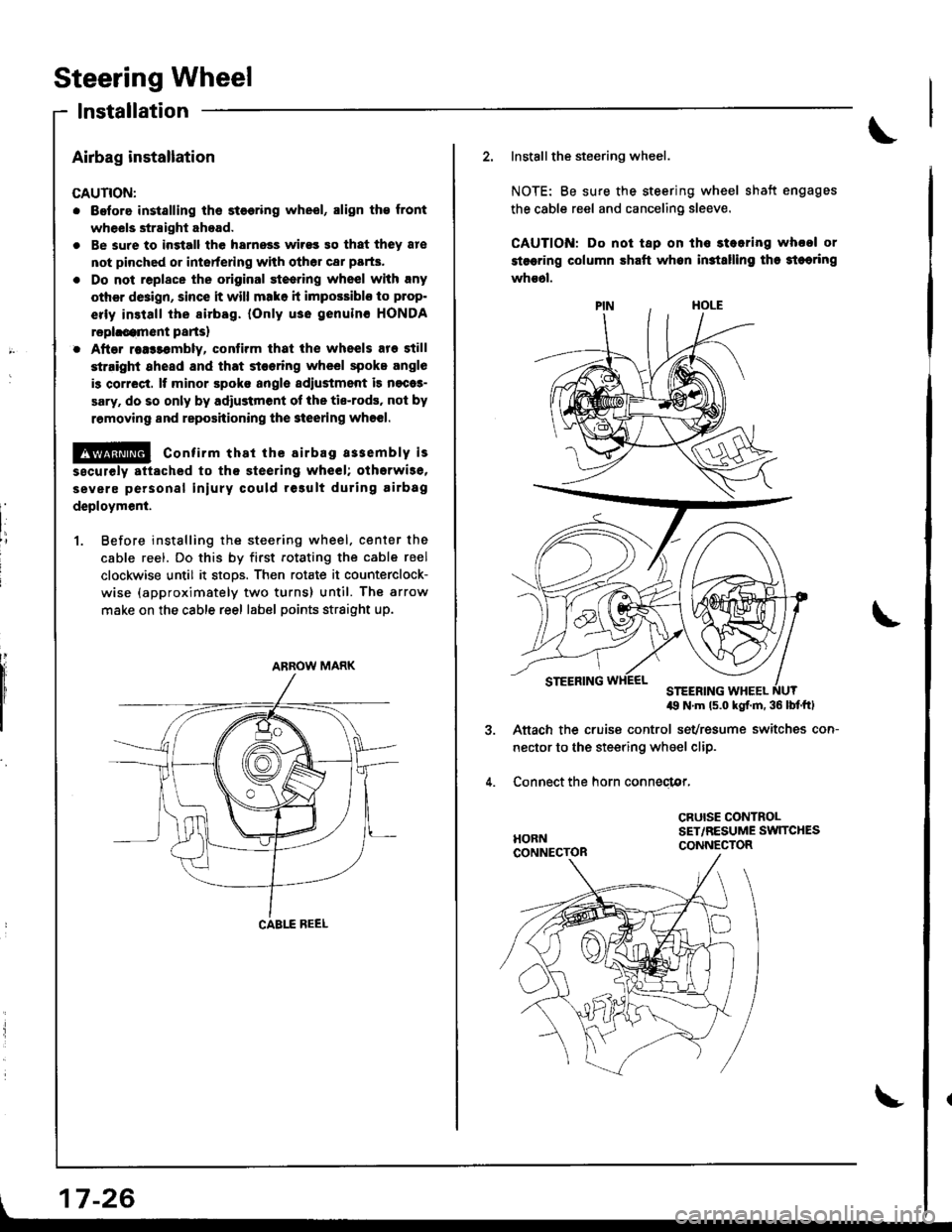
Steering Wheel
lnstallation
Airbag installation
CAUTION:
. Before installing ths st€€ring wheel, align th€ front
wheels straight ahead.
. Be sure to ingtall the harnoss wirss 90 that they 8re
not pinched or intorfering with other car parts.
. Do not replace the original st€ering wheel with rny
other d8ign, since it will mako h impossiblo to p.op-
erly install the sirbag. {Only use genuinc HONDA
rephcamont parts)
. After rea$embly, contirm that ih€ wheels are still
st.ight 8head and that stooring wheel spoke angle
is correct. It minor spoko aogle sdiustment is n€cas-
sary. do so only by adiustment ol the tis-rods, not by
removing and reposhioning the 3teering who€|.
!@ confirm thst the airbag a33embly is
sscurely attached to th€ steering wheel; otherwi3e,
severe personal iniury could result during airbag
deploymenl.
1. Before instslling the steering wheel. center the
cable reel. Do this by first rotating the cable reel
clockwise until it stoos. Then rotate it counterclock-
wise (approximately two turns) until. The arrow
make on the cable reel label points straight up.
ARROW MARK
| 17-26
\
2. Installthe steering wheel.
NOTE: Be sure the steering wheel shatt engages
the cable reel and canceling sleeve.
CAUTION: Do not tap on ths stearing whool or
stsering column shaft whon in3tslling tha 3teoring
whs6l.
49 N'm ls.o kgf.m. 36 lbf'ftl
Aftach the cruise control sevresume switches con-
nector to the steering wheel clip.
Connect the horn conneclor,
CRUISE CONTROLSET,/RESUME SW]TCHESCONNECTOR
Page 692 of 1681
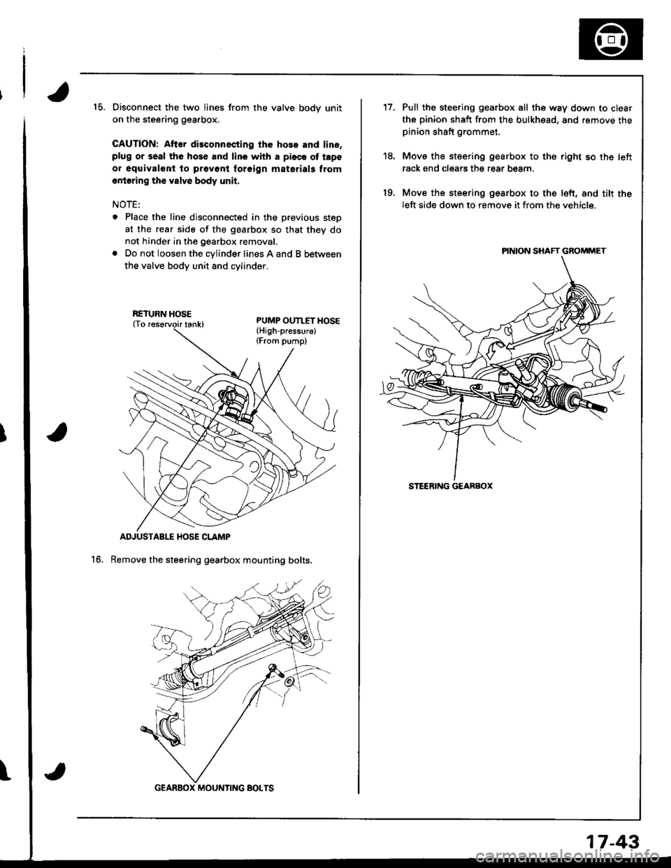
15. Disconnect the two lines from the valve bodv unit
on the steering gearbox.
CAUTION: After disconnscting the hose and line,plug or seal the hose and lino whh I pi6ce ot tape
o. oquivalent to prevont foreign matarials from
6rioring the vslve body unit,
NOTE:
. Place the line disconnected in the previous steD
at the rear side of the gearbox so that they do
not hinder in the gearbox removal.
. Do not loosen the cylinder lines A and B between
the valve body unit 8nd cvlinoer.
ADJUSTABLE HOSE CLAMP
Remove the steering gearbox mounting bolts.16.
\
RETURN HOSE
GEARBOX MOUNTING BOTTS
17-43
't7.
19.
Pull the steering gearbox all the way down to clear
the pinion shaft from the bulkhead, and remove thepinion shaft grommet.
Move the steering gearbox to the right so th€ left
rack end clears the rear beam.
Mov€ the steering gearbox to the loft, and tilt theleft side down to remove it from the vehicle.
PINION SHAFT GBOMMET
STEERING GEARBOX
Page 706 of 1681
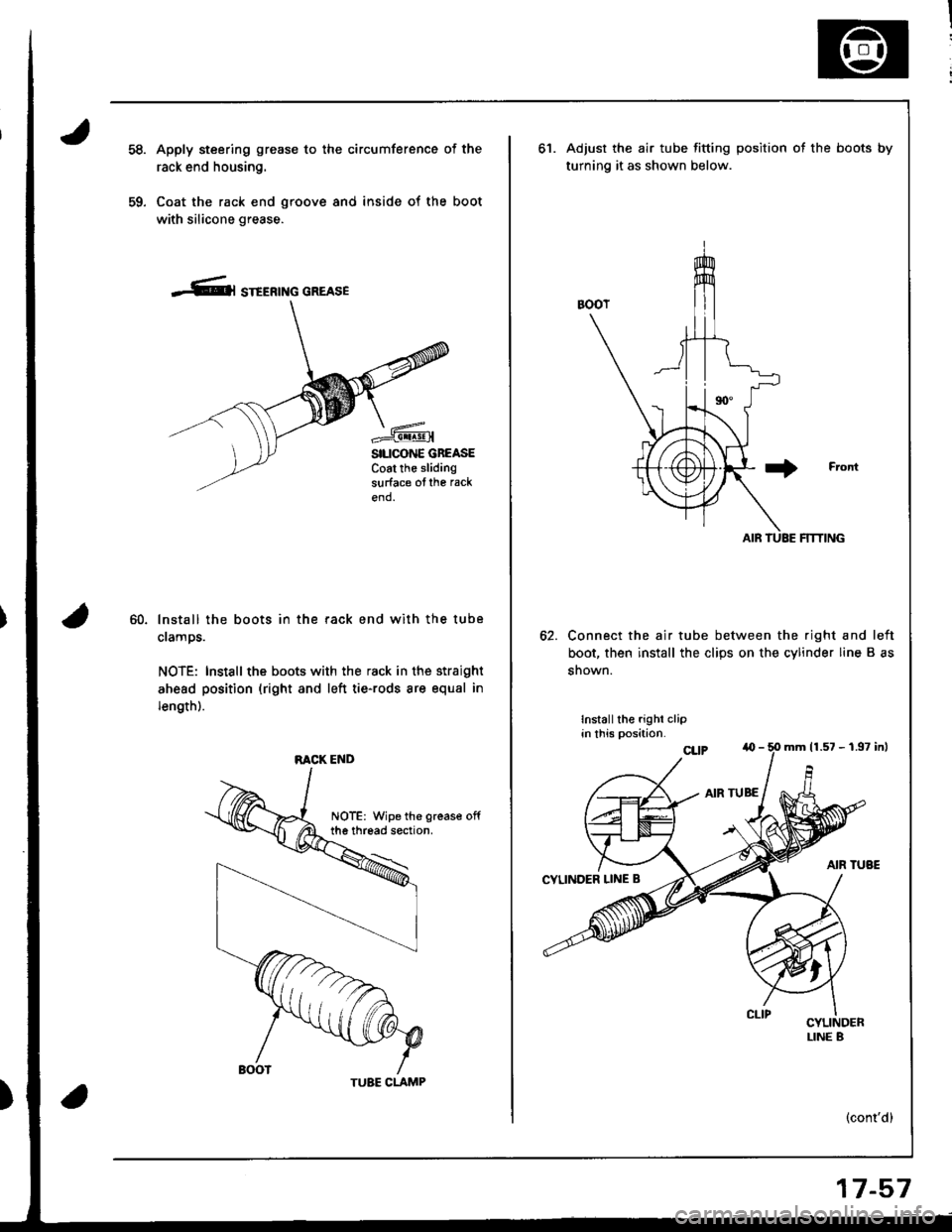
59.
Apply steering grease to the circumference of the
rack end housing.
Coat the rack end groove and inside of the boot
with silicone grease.
-Cl STEERTNG GREASE
SILICONE GBEASECoat the slidingsurface ofthe rack
end.
60.lnstall the boots in the rack end with the tube
clamps.
NOTE: Install the boots with the rack in the straight
ahead position (right and left tie-rods are equal in
length).
RACK END
TUBE CLAMP
17-57
ot.Adjust the air tube fitting position ot the boots by
turning it as shown below.
Connect the air tube between the right and left
boot, then install the clips on the cylinder line B as
snown.
Installthe righi clipin this position.
(cont'd)
mrn 11.57 - 1.97 inl
Page 715 of 1681
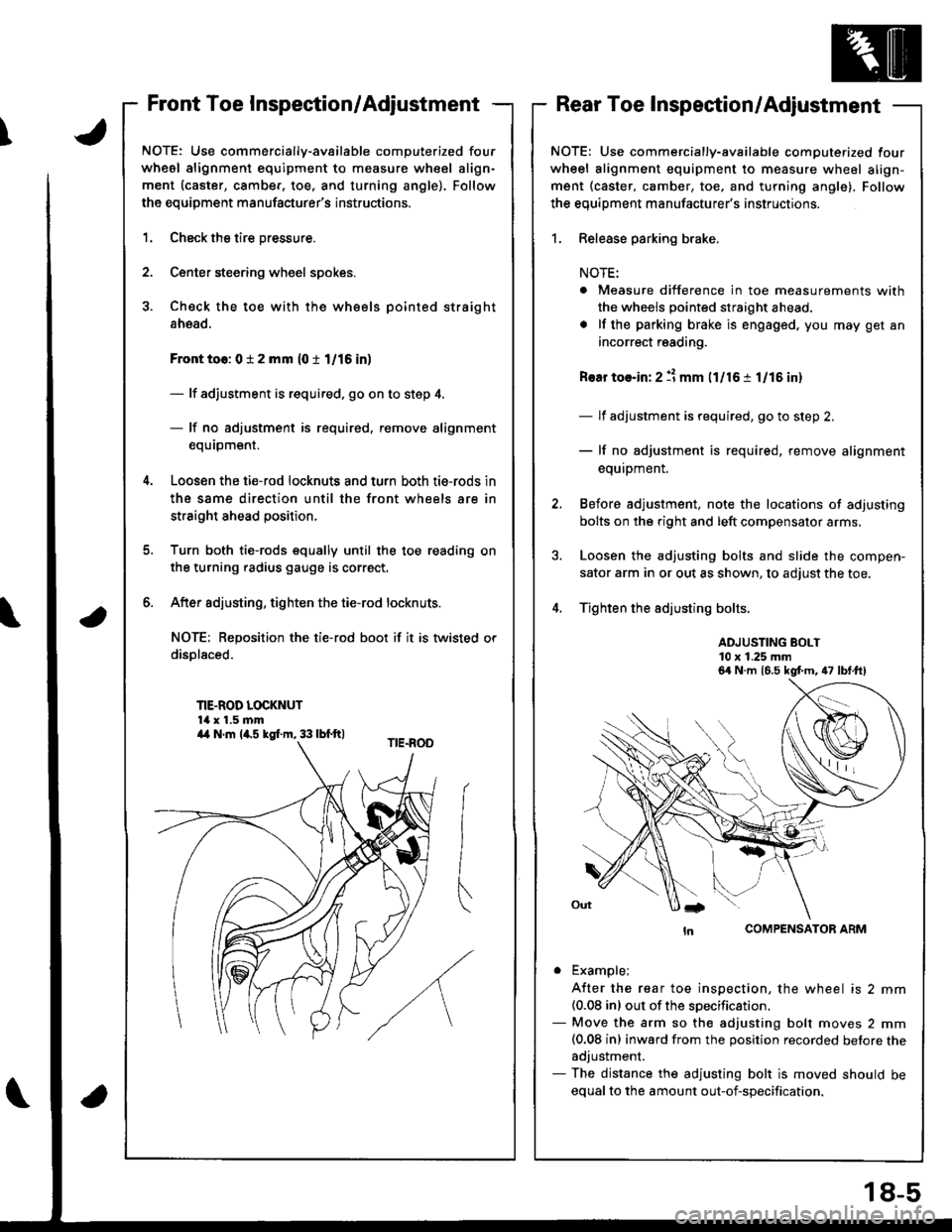
\
Front Toe Inspection/AdjustmentRear Toe Inspection/Adjustment
NOTE: Use commercially-available computerized four
whesl alignment equipment to measure wheel align-
ment (caster, camber, toe. and turning angle). Follow
the equipment manufacturer's instructions.
1.
2.
Check the tire pressure.
C€nter steering wheel spokes.
Check the toe with the wh€els pointed straight
ahead.
Front to6: 0 i 2 mm (0 t 1/16 in)
- lf adjustment is required. go on to step 4.
- lf no adjustment is required, remove alignment
equrpm€nr,
Loosen the ti€-rod locknuts and turn both tie-rods in
the same direction until the front wheels are in
straight ahead position.
Turn both tie-rods equally until the toe reading on
the turning radius gauge is correct.
After sdjusting, tighten the tie-rod locknuts.
NOT€: Reposition the tie-rod boot if it is twisted or
displaced.
TIE-ROD LOCKNUT14 x 1.5 mm
6.
a
NOTE: Use commercially-available computerized four
wheel alignment equipment to measure wheel align-
ment (caster, camber, toe, and turning angle), Follow
the equiDment manufacturer's instructions.
1. Release parking brake.
NOTE:
. Measure difference in toe measurements with
the wheels pointed straight ahead.
. lf the parking brake is engaged. you may get an
incorrect reading.
Rear toe-in: 2 11 mm l1l16 i 1/15 in)
- lf adjustment is required, go to step 2.
- lf no adjustment is required, remove alignment
equipment.
Before adjustment, note the locations of adjusting
bolts on the right and left compensator arms.
Loosen the adjusting bolts and slide the compen-
sator arm in or out as shown, to adjust the toe.
Tighten the adjusting bolts.
ADJUSTING BOLT10 x 1.25 mm
COMPENSATOR ARM
. Example;
A{ter the rear toe inspection, the wheel is 2 mm(0.08 inl out of the soecification.- Move the arm so the adjusting bolt moves 2 mm(0.08 inl inward from the position recorded betore theadjustment.- The distance the adjusting bolt is moved should be
equal to the amount out-of-specification.
6a N.m 16.5 kgt m, 47 lbt.ft)
a4 N.m la.s kgI.m, 33 lbf.ft)
18-5