engine coolant HONDA INTEGRA 1998 4.G Repair Manual
[x] Cancel search | Manufacturer: HONDA, Model Year: 1998, Model line: INTEGRA, Model: HONDA INTEGRA 1998 4.GPages: 1681, PDF Size: 54.22 MB
Page 1500 of 1681
Gauges (cont'd)
- How the Circuit Works
When the ignition switch is in ON (ll) or START (lll),
battery voltage is supplied through fuse 25 to the
gauges in the gauge assembly.
Speedometer and Odometer
The odometer and speedometer drive circuits
receive pulses lrom the vehicle speed sensor
(VSS). The pulse rate increases as the car
accelerates. The frequency and duration of these
input pulses are measured and displayed by the
speedometer, odometer and tripmeter.
Tachometer ('98-'99 Models)
The tachometer drive circuit receives oulses from
the ignition control module (lCM) in the distributor
assembly. The solid-state tachometer then displays
these pulses as engine speed. For each 200 pulses
per minute from the ignition control module (lCM),
the tachometer displays 100 RPM.
Tachometer ('00 Model)
The tachometer drive circuit receives pulses f rom
the PCM or ECM. The solid-state tachometer then
displays these pulses as engine speed. For each
200 oulses oer minute trom the PCM or ECM the
tachometer displays 1 00 RPM.
Engine Coolant Temperature Gauge and Fuel
Gauge
The engine coolant temperature gauge has two
intersecting coils wound around a permanent
magnet rotor. Voltage applied to the coils, through
fuse 25, generates a magnetic field. The magnetic
field, controlled by the engine coolant temperature
gauge sending unit, causes the rotor to rotate and
the gauge needle to move. As the resistance in the
sending unit varies, current through the gauge coils
changes. The gauge needle moves toward the coil
with the strongest magnetic tield. The fuel gauge
works the same way.
The engine coolant temperature gauge sending
unit's resistance varies from about 137 ohms at low
engine temperature to between 30-46 ohms at high
temperature (radiator fan running).
The fuel gauge sending unit's resistance varies from
about 2-5 ohms at full, to about 110 ohms at empty.
When you turn the ignition switch to LOCK (0), the
gauge remains at the last reading until you turn lhe
ignition switch to ON (ll) or START (lll) again.
Refer to the Service Manual (Section 23, Electrical)
for specific tests or troubleshooting procedures.
81'2
Page 1598 of 1681
Connector ldentification and Wire Harness Routing (cont,d)
Connector
or
Terminal
Number ot
Cavities/
Color
LocationConnects toNotes
Engine Wire Harness (RS, LS, GS)
c101
c102
c103
c104
c105
c106
c 107
c108
c108
c'1 09
c110
c111
cl12
c113
c'114
c115
c116
c117
c118
c119
c1 19
c120
c121
c122
c123
c124
cl25
cl26
c127
Ql28
c128
c129
c 129
c130
c'l30
c131
4.GRY
1O.GRY
14-GRY
6-GRY
1.BLK
2-GRY
,1-BLK
2-GRY
2.GRY
1O-GRY
2-GRY
2-GRY
3-GRY
4-GRY
3-GRY
3-GRY
2-GRY
2.BLK
.1-BLK
4-GRN
3-GRN
2-GRY
2.BLK
2-BLK
2-BLK
2.BLK
8-GRY
2-GRY
14-GRY
3-GRY
2.GRY
2.GRY
2-BLK
3-GRY
2-BLK
2-BLK
Right side of engine compartment
Right side of engine compartment
Right side ot engine compartment
Right side of engine compartment
Right end of engine
Right end of engine
Right end of engine
Transmission
Transmission
lvliddle ol engine
Lett rear underside of engine
Right side ol engine
Rear of engine compartment
Middle rear ol engine compartment
Middle ol engine
Middle of engine
Middle ol engine
l\4iddle of engine
Middle of engine
Left end ot engine
Lett end of engine
Middle of engine
N,liddle ol engine
Middle of engine
Middle of engine
Middle of engine
Left rear corner of engine compt.
Lelt rear corner of engine compt.
Left rear corner of engine compt.
Transmission
Transmission
Transmission
Transmission
Transmission
Transmission
Transmission
Main wire harness
Main wire harness
Main wire harness
Main wire harness
Starter solenoid
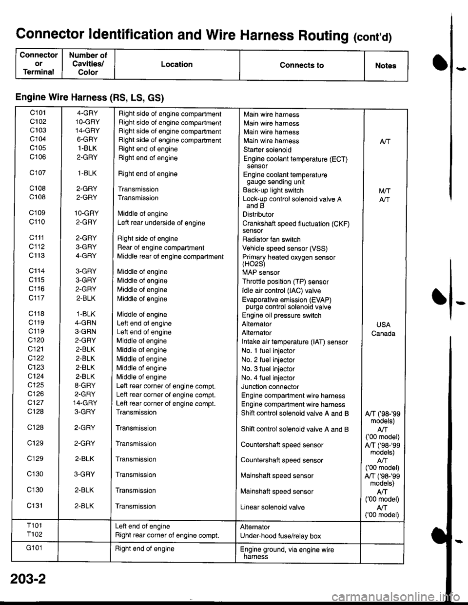
Engine coolant temperature (ECT)sensor
Engine coolant temperaturegauge sending unit
Back-up light switch
Lock-up control solenoid valve Aand B
Distributor
Crankshaft speed fluctuation (CKF)sensor
Radiator fan switch
Vehicle speed sensor (VSS)
Primary heated oxvoen sensor(H02s)
MAP sensor
Throttle position (TP) sensor
ldle air control (lAC) valve
Evaporative emission (EVAP)purge control solenoid valve
Engine oil pressure switch
Alternator
Alternator
Intake air temperature (lAT) sensor
No. I fuel injector
No. 2 fuel injector
No. 3 tuel injector
No. 4 fuel injector
Junction connector
Engine compartment wire harness
Engine compartment wire harness
Shitt control solenoid valve A and B
Shift control solenoid valve A and B
Countershaft speed sensor
Countershatt speed sensor
lvtainshatt speed sensor
Mainshaft speed sensor
Linear solenoid valve
NT
[/VT
A"/T
USA
Canada
A/T (98199models)
AIT('00 model)
A,/T ('98-'�99models)
('00 model)
A,/T f98-'99models)
Atf('00 model)
AN('00 model)
T101
T102
Left end of engine
Right rear corner of engine compt.
Alternator
Under-hood fuse/relay box
G'101Right end ot engineEngine ground, via engine wirenarness
o
I
203-2
Page 1600 of 1681
Connector ldentification and Wire Harness Routing (conrd)
Connector
ol
Terminal
Number of
Cavities/
Golor
LocationConnects toNotes
Engine Wire Harness (GS-R, Type R)
c101
c102
c103
c104
U IUC
c106
c107
c108
c109
c110
c111
c112
c113
c114
c115
c116
c117
c118
c11 9
c119
c120
c121
cl22
c123
vtzl
wt10
c127
c131
c132
c133
c134
4-GRY
1O-GRY'I4-GRY
3-GRY
1 -BLK
2-GRY
1.BLK
2-GRY
1O-GRY
2-GRY
2-GRY
3-GRY
4-GRY
3-GRY
3.GRY
or BLU
2-GRY
2-BLK
1 -BLK
4-GRN
3-GRN
2.GRY
2-BLK
2-BLK
2-BLK
2-BLK
8-GRY
2.GRY
14-GRY
1-GRY
2-GRN
2-GRN
2-GRY
Right side of engine compartment
Right side of engine compartment
Bight side of engine compartment
Right side of engine compartment
Right side of engine compartment
Right end of engine
Right end of engine
Transmission
Middle end of engine
Left rear underside of engine
Right end of engine
Right end of engine compartment
Middle rear of engine compartment
Middle of engine
Middle of engine
Middle of engine
Middle of engine
Middle of engine
Left end of engine
Left end of engine
Middle of engine
Middle of engine
Middle of engine
Middle of engine
Middle of engine
Left rear corner of engine compt.
Left rear corner of engine compt.
Left rear corner of engine compt.
Right side of engine
Right side of engine
Left end of engine
Left end of engine
Main wire harness
Main wire harness
Main wire harness
Main wire harness
Starter solenoid
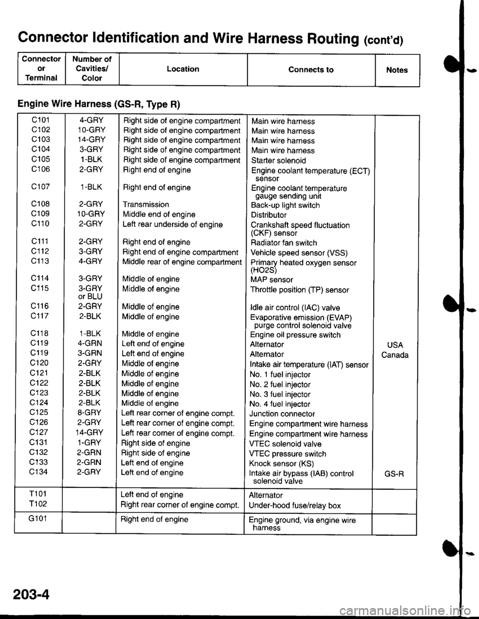
Engine coolant temperature (ECT)
sensor
Engine coolant temperaturegauge sending unit
Back-up light switch
Distributor
Crankshaft speed f luctuation(CKF) sensor
Radiator fan switch
Vehicle speed sensor (VSS)
Primarv heated oxvoen sensor(Hozs)
MAP sensor
Throttle position (TP) sensor
ldle air control (lAC) valve
Evaporative emission (EVAP)purge control solenoid valve
Engine oil pressure switch
Alternator
Alternator
Intake air temperature (lAT) sensor
No. 1 fuel injector
No. 2 fuel injector
No. 3 fuel injector
No. 4 fuel injector
Junction connector
Engine compartment wire harness
Engine compartment wire harness
VTEC solenoid valve
VTEC pressure switch
Knock sensor (KS)
Intake air bypass (lAB) controlsolenoid valve
USA
Canada
GS.R
T101
r102
Left end of engine
Right rear corner of engine compt.
Alternator
Under-hood fuse/relay box
G101Right end of engineEngine ground, via engine wirenarness
203-4
Page 1640 of 1681
Under-hood Emissions Gontrol Label
Emission GrouP ldentification
Example:
50 STATE TIER 1
THIS VEHICLE CONFORMS TO U.S. EPA AND CALIFOR-
NIA REGULATIONS APPLICABLE TO 2OO1 MODEL YEAR
NEW PASSENGER CARS.
50 STATE TLEV + NLEV (UNRESTRICTEDI:
THIS VEHICLE CONFORMS TO U.S. EPA NLEV REGULA-
TIONS APPLICABLE TO 2OO1 MODEL YEAR NEW TLEV
PASSENGER CARS AND CALIFORNIA REGULATIONS
APPLICABLE TO 2OO1 MODEL YEAR NEW TLEV PAS.
SENGER CARS.
CANADIAN TIER 1
THIS VEHICLE CONFORMS TO CANADIAN TIER 1 STAN.
DARDS FOR 2OO1 MODEL YEAR NEW PASSENGER
HONDA l/0T0R c0. , LTD P72-401
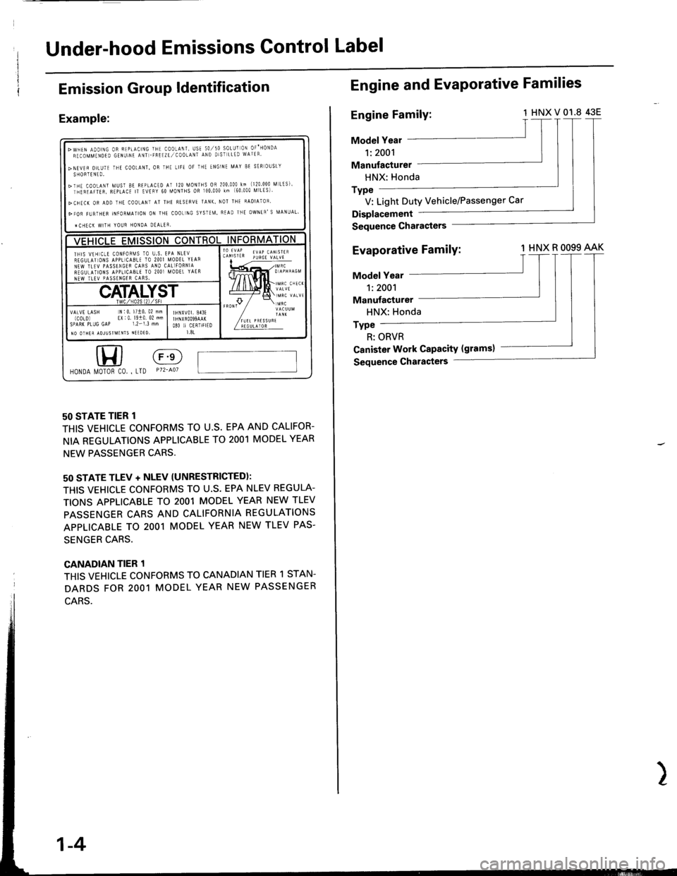
>wHEN ADDTNG oR FEPtActNG THE co0LANT, usE 50,/50 soLUr oN oF'HoNDARECOMMTNDED GENUINE ANT -FREIZE,/COOtANT AND DIST LLED WATEF'
>NEVEfl DILUTE THE COOtANT, OR IHE LIFE OF THE ENGINF MAY BE SER]OUSLYSHORTENTO.
>THE COoLANT MUST BE BEPLACED AT I20 MONTHS OR 200.000 km (120 000 [,| LtS]'rnirilrren, B€pLAcE rT EvEFY 60 [roNTHs oR 100.000 km (60 000 [ilLEs)'
>CHEC( OR ADD THE COOLANI AT THE RESERVE TANK. NOT THE RADIATOF'
>FOR FI,JRTHER INFORMATION ON ]HE COOL]NG SYSTEM. READ THE OWNEN'S MANUAL'
ICHECK WITH YOUR HONOA DEALER,
ll,5lil, 5;i;,'iX;';'THIS VTH CtE CONFOF[IS TO U.S. EPA NLEVREGULATIONS APPL]CABLE TO 2OO] MODEL YTAsNEW TLTV PASSENGEF CAFS AIID CAL]FORNIAREGUTATIONS APPLICABLE TO 2OO] MOOET YAERNEW TLEV PASSENGER CARS.
IHNXVOI, 813FI HNXROO99AAKO8O II CERIIFIED1.81
VATVE LASH N:0. l/10. 02 mm(COLD) EX|0 19i0 02 mmSPARK PLUG GAP 1.2-1.3 mmIO OTHER ADJUSIMENIS NIEDTO,
Engine and EvaPorative Families
Engine Family:1HNXV01.8 43E
Model Year
1:2001
Manufacturer
HNX: Honda
Type
V: Light Duty Vehicle/Passenger Car
Displacement
Sequence Gharasters
Evaporative FamilY:1 HNX R OO99 AAK
Model Year
1:2001
Manufacturer
HNX: Honda
Type
R: ORVR
Ganister Work CaPacitY (gramsl
Sequence Characters
1-4
Page 1648 of 1681
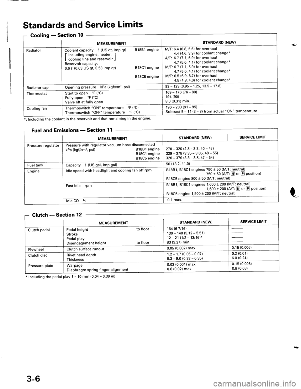
Standards and Service Limits
missions - Section 11
* Including the pedal play 1 - 10 mm (0.04 - 0.39 in).
0Gooling - Sectlon
MEASUREMENTSTANDARD (NEW}
RadiatorCoolant capacity / (US qt, lmp qt) 81881 engine
I Including engine, heater, II cooling line and reservoir IReservoir capacity:0.6 f (0.63 US qt, 0.53 lmp qt) 818C1 engine
818C5 engine
M/T: 6.4 (6.8, 5.6) for overhaul4.4 14.6,3.9) for coolant change*
A,/T: 6.7 (7.1, 5.9) for overhaul4.7 $.0,4.1)for coolant change*
M/T: 6.7 (7.1,5.9) for overhaul4.7 (5.0, 4.1) for coolant change*
M/T: 6.5 (6.9, 5.7) for overhaul4.5 (4.8, 4.0) for coolant change*
Radiator capOpening pressure kPa (kgf/cm'�, Psi)93 - 123 (0.95 - 1.25, 13.5 - 17.8)
ThermostatStart to open 'F ("C)
Fully open "F ("C)
Valve lift at fully open
169 - 176 (76 - 80)194 (90)
8.0 (0.31)min.
Cooling fanThermoswitch "ON" temperature "F ('C)
Thermoswitch "OFF" temperature "F ("C)196 - 203 (91 - 95)Subtract 5 - 14 (3 - 8) from actual "ON" temperature
*: Including the coolant in the reservoir and that remaining in the engine
Fuel and E
MEASUREMENTSTANDARD (NEW}SERVICE LIMIT
Pressure regulatorPressure with regulator vacuum hose disconnected
kPa (kgf/cm'�, psi) 81881 engine818C1 engine818C5 engine
270 - 320 (2.8 - 3.3, 40 - 47].
329 - 378 (3.35 - 3.85, 48 - 55)
320 - 370 (3.3 - 3.8, 47 -541
Fuel tankCapacity / (US gal, lmp gal)50 (13.2, 11.0)
Engineldle speed with headlight and cooling fan off rpm81881, 818C1 engines 750 t 50 (M/T: neutral)750 I 50 (A/T: N or E Position)818C5 engine 800 t 50 (M/T: neutral)
Fast idle rpmB1881, 818C1 engines 1,600 t 200 (M/T: neutral)1,600 t 200 (A/T: E or E Position)818C5 engine 1,500 t 200 (M/T: neutral)
ldle CO %0.1 max.
Clutch - Section 'lZ
MEASUREMENTSTANDARD (NEW}SERVICE LIMIT
Clutch pedalPedal height to floor
StrokePedal playDisengagement height to floor
164 (6 7/16)130 - 140 (5.12 - 5.51)12 -21 (12 - 13/16)*83 (3.27) min.
FlywheelClutch surface runoul0.05 (0.002) max,0.15 (0.006)
Clutch discRivet head depthThickness
1.2 - 1.7 (0.05 - 0.07)8.3 - 9.0 (0.33 - 0.35)0.2 (0.01)
6.0 (0.24)
Pressu re plateWarpageDiaphragm spring finger alignmenl
0.03 (0.001) max.0.6 (0.021 max.
0.15 (0.006)
0.8 (0.03)
3-6
Page 1670 of 1681
Cooling
Radiator
Engine Coolant Refilling and
Bfeeding .... 10-2
NOTE: Refer to the '98 INTEGRA Service Manual, PiN 61ST705, for the
items not shown in this section.
,f
Outline of ModelChange
Engine coolant has been changed.
rfltmlfr
Page 1671 of 1681
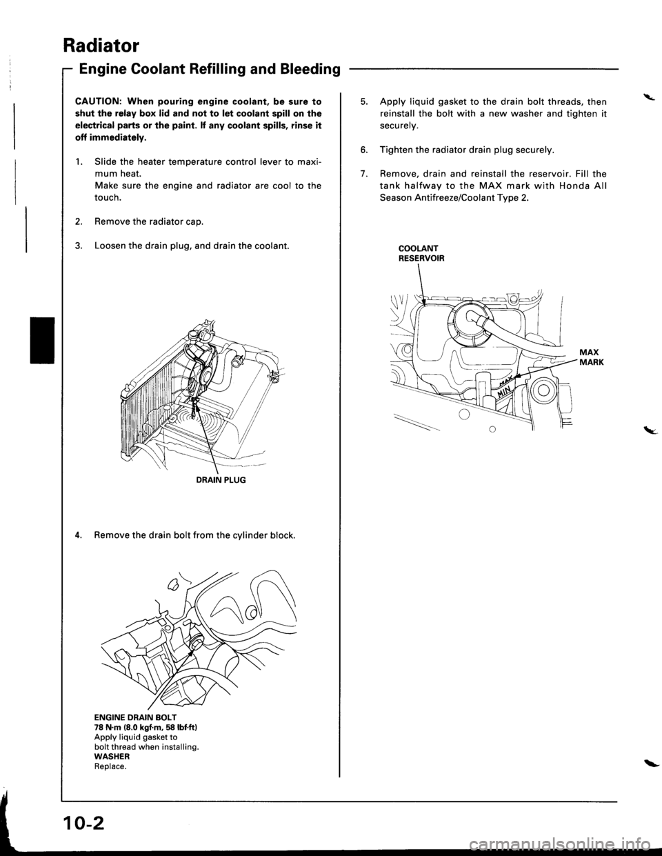
Radiator
Engine Goolant Refilling and Bleeding
CAUTION: When pouring engine coolant, be sure to
shut the relay box lid and not to let coolant spill on the
electrical parts or the paint. lf any coolant spills, rinse it
off immediately.
1. Slide the heater temperature control lever to maxi-
mum heat.
Make sure the engine and radiator are cool to the
touch.
2. Remove the radiator caD.
3. Loosen the drain plug, and drain the coolant.
4. Remove the drain bolt from the cylinder block.
ENGINE DRAIN BOLT78 N.m (8.0 kgf.m,58 lbf.ftlApply liquid gasket tobolt thread when installing.WASHERReolace.
DRAIN PIUG
I \.--
\_-l - I
\
6.
7.
5. Apply liquid gasket to the drain bolt threads, then
reinstall the bolt with a new washer and tighten it
securely.
Tighten the radiator drain plug securely.
Remove, drain and reinstall the reservoir. Fill the
tank halfway to the MAX mark with Honda All
Season Antifreeze/Coolant Type 2.
COOLANTRESERVOIR
tW.
\-
Page 1672 of 1681
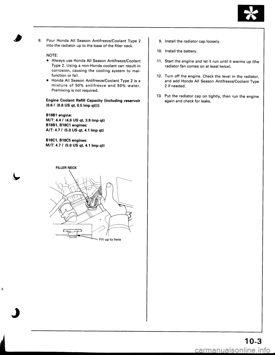
tt.Pour Honda All Season Antifreeze/Coolant Type 2into the radiator up to the base of the filler neck.
NOTE:
o Always use Honda All Season Antifreeze/Coolant
Type 2. Using a non-Honda coolant can result incorrosion, causing the cooling system to mal-function or fail.
o Honda All Season Antifreeze/Coolant Type 2 is amixture of 50% antifreeze and 50% water.Premixing is not required.
Engine Coolant Refill Gapacity [including reservoir(0.6 f {0.6 US qt, 0.5 lmp qtlll:
81881 engine:
M/T: 4.4 / {4.6 US qt, 3.9 lmp qtl
B18B1, Bl8Cl engines:
AIT:4.7 / (5.0 US qt,4.1 lmp qtl
818C1, B18C5 engines:
MIT:4.7 / (5.0 US qt,4.1 lmp qtl
FILLER NECK
Fill up to here
9.
10.
11.
12.
Install the radiator cap loosely.
Install the battery.
Start the engine and let it run until it warms up (the
radiator fan comes on at least twice).
Turn off the engine. Check the level in the radiator,
and add Honda All Season Antifreeze/Coolant Type2 if needed.
Put the radiator cap on tightly, then run the engine
again and check for leaks.
13.