engine coolant HONDA INTEGRA 1998 4.G Owner's Guide
[x] Cancel search | Manufacturer: HONDA, Model Year: 1998, Model line: INTEGRA, Model: HONDA INTEGRA 1998 4.GPages: 1681, PDF Size: 54.22 MB
Page 464 of 1681
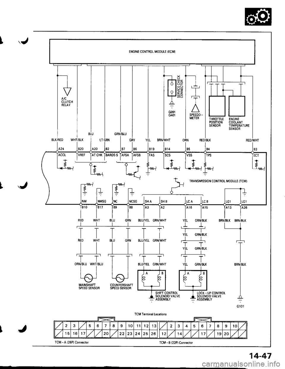
'.J
THROTTLErcsm0NSENSOR
ENGINECOOLANTTEMPERATURESENSOR
WHT/BLKBLK/RED
820424
OBNREO/BLK
84
J
MAINSHAFI COUNTERSHAFISPEED SENSOR SPfED SENSOR
I SHIFT CONTROL I LOCK -UP CONTBOL
+135Eil,?1o'uo'u' 4i85El,o''P'uo'u'
TCM T6nninal locations
TCM -B l22P)Conn€ctor
VREF IATCHK IBASOSS IAFSA IAFSB IFAS ISCS
----T;- t-T-*
+.. | +.., I + ,+
l+ | J l/vt-l .i{-'1M-l L-{-lr^/t-lt't'/!-?
*\::
r--rr!\.1 -r!\./ rartsurssrot coNTFoL M'DULE tTcMr
ltEltn r' -rrt= t= t? t=
NMSG INC INCSG ISH A ISH B ILC A ILC B
576I101112578I10
151617,/1,/20251214,/1,/171920,/1,/J
TCM -A (26P1 Connector
14-47
Page 466 of 1681
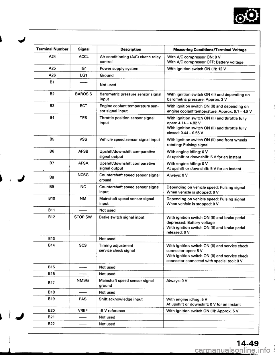
Terminal NumberSignalDescriptionMaasuring Conditlons/Tarminal Voliage
424ACCLAir conditioning (Ay'C) clutch relay
control
With A,/C comDressor ON: 0 V
With Ay'C compressor OFF: Battery voltage
A25tG1Power supply systemWith ignition switch ON (ll)r 12 V
426LG1Ground
B1Not used
82BAROS SBarometric pressure sensor signal
input
With ignition switch ON (ll) and depending on
barometric pressure: Approx. 3 V
B3ECTEngine coolant temperature sen-
sor signal input
With ignition switch ON (ll) and depending on
engine coolant tem perature: Approx. 0.1 - 4.8 V
B4TPSThrottle position sensor signal
input
With ignition switch ON (ll) 8nd throttle fully
open: 4.14 - 4.82 V
With ignition switch ON (ll) and throttle fully
closed: 0.44 - 0.56 V
B5VSSVehicle speed sensor signal inputWith ignition switch ON (ll) and front wheels
rotating; Pulsing signal
B6AFSBUpshifvdownshift comparative
signal output
With engine idling: 0 V
At uDshift or downshift: 5 V for an instant
B7AFSAUpshifvdownshift com parative
srgnal output
With engine idling: 0 V
At upshift or downshift: 5 V for an instant
B8NCSGCountershaft speed sensor signal
ground
Always: 0 V
B9NCCountershaft speed sensor signal
Input
Depending on vehicle speed: Pulsing signal
When vehicle is stopped:0 V
B10NMMainshaft speed sensor signal
input
Depending on vehicle speed: Pulsing signal
When vehicle is stoDoed: 0 V
811Not used
812STOP SWBrake switch signal inputWith ignition switch ON {ll) and b.ake pedal
depressed: Battery voltage
With ignition switch ON (lll and brake pedal
released:0 V
813Not used
814scsTiming adjustment
service check signal
With ignition switch ON (ll) and service check
connector oDen:5 V
With ignition switch ON (ll) and service check
connector connected with special tool: 0 V
815Not used
816Not used
817NMSGMainshaft speed sensor signalgroundAlways: 0 V
818Not used
819FASShift acknowledge inputWith engine idling: 5 V
At upshift or downshift: 0 V for an instant
820VBEF+5 V referenceWith ignition switch ON {lll: Approx. 5 V
82'lNot used
Not used
14-49
Page 471 of 1681
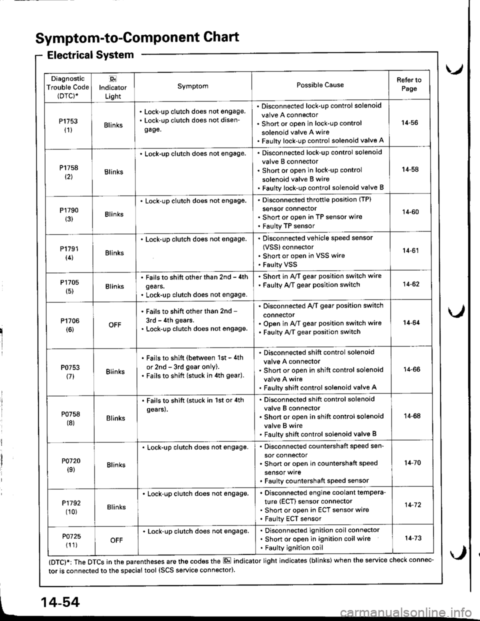
Diagnostic
Trouble Code(Drc)*
,94
lndicator
Light
SymptomPossible CauseRefer to
Page
P1153(1)Blin ks
Lock-up clutch does not engage,
Lock-up clutch does not disen-
gage.
Disconnected lock-up control solenoid
valve A connector
Short or open in lock-uP control
solenoid valve A wire
Faulty lock-up control solenoid valve A
14-56
P1758
t2lBlinks
. Lock-up clutch does not engage.Disconnected lock-up control solenoid
valve B connector
Short or open in lock-uP control
solenoid valve B wire
Faulty lock-up control solenoid valve B
14-58
P1790(3)Blinks
. Lock-up clutch does not engage.Disconnected throttle position (TP)
sensor connector
Short or open in TP seflsor wire
Faulty TP sensor
14-60
P1191(4)Blinks
. Lock-up clutch does not engage.Disconnected vehicle speed sensor
{VSS} connector
Shon or open in VSS wire
Faulty VSS
14-61
P1705
(5)Blinks
. Fails to shift other than 2nd - 4th
gears.
. Lock-up clutch does not engage.
. Shod in AvT gear position switch wire
. Faulty A,/T gear position switch14-62
P1706(6)OFF
' Fails to shift other than 2nd -
3rd - 4th gears.
. Lock-up clutch does not engage.
Disconnected A/T gear position switch
connector
Open in A/f gear position switch wire
Faulty A/f gear position switch
14-64
P0753
(71Blinks
. Fails to shift (between 1st - 4th
or 2nd - 3rd gear only).. Fails to shift (stuck in 4th gear).
Disconnected shift control solenoid
valve A connector
Short or open in shift control solenoid
valve A wire
Faulty shift control solenoid valve A
14-66
P0758(8)Blinks
. Fails to shift (stuck in 1st or 4th
gears).
Disconnected shift control solenoid
valve B connector
Short or open in shift control solenoid
valve B wire
Faulty shift control solenoid valve B
14-68
P0120(9)Blin ks
Lock-up clutch does not engage.Disconnected countershaft speed sen-
sor connector
Short or open in countershaft speed
sensor wrre
Faulty countershaft speed sensor
1+10
P1192
00)Blinks
. Lock-up clutch does not engage,Disconnected engine coolant tempera-
ture (ECT) sensor connector
Short or open in ECT sensor wire
Faulty ECT sensor
14-72
P0725
{1 1)OFF
Lock-up clutch does not engage.Disconnected ignition coil connector
Short or open in ignition coil wire
Faulty ignition coil
14-73
Symptom-to-ComPonent Chart
Electrical System
(DTC)*: The DTCS in the parentheses are the codes the E indicator light indicates {blinks) when the service check connec-
tor is connected to the special tool (SCS service connector)
4-54
Page 489 of 1681
Electrical Troubleshooting
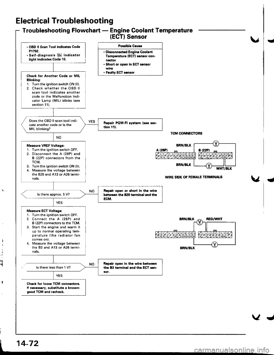
Troubleshooting Flowchart - Engine Coolant Temperature
(EGTISensor
Polribl. Cluta
. Dirconnoct.d Engin. CoollntTampaolur€ IECTI aanaor con.noctot. Short or opcn In ECT..n.or
. F.ulty ECT r.n.or
Tctrrt oot{NEcToRs
WIRE SIDE OF FEMAII TERi'IINAIS
U
{
M6esur. ECT Voh.ge:1. Turn the ignition switch OFF.2. Connect the A (26P) andB (22P) connectors to the TCM.3. Start the engine and w6rm ituP to normal operating tem-pe ratu re (the radiator fancomes on),4, Measure the voltage betweenthe 83 and A13 or A26 termi-nats.
Ii
:
rt.fls there less than 1 V?
Ch.cl fo. looso TCM connac{or3,t nacaasary, substituto a known"good TCM rnd r.chock.
' OBD ll Scsn Tool Indicat6 CodeP1792.. Sett'diagno3i3 E indicatollight indicates Code 10.
Chock tor Anothor Codo or MILBlinking:1. Turn the ignition switch ON (ll).
2. Check wh€ther rhe OBD llscan tool indicates anothercode or the Malfunction Indi-cator Lamp (MlL) blinks (see
section 11).
Does the OBD ll scan tool indi-cate another code or is theMIL blinking?
Moasure VREF Voh.go:1. Turn the ignition switch OFF.2. Disconnect the A {26P) andB (22P) conneotors from theTCM.3. Turn the ignition switch ON (ll).
4. Measu.e the voltage betweenthe 820 and A13 or A26 tormi-nals.
Bap|ir open or thort in tha wircb.two.r th. B:m t.rminll .nd thoECM.
ls there approx. 5 V?
napalr opln in iha wlra brtwaanthe lB t.rminrl lnd th. ECT r.n-ao1.
Page 497 of 1681
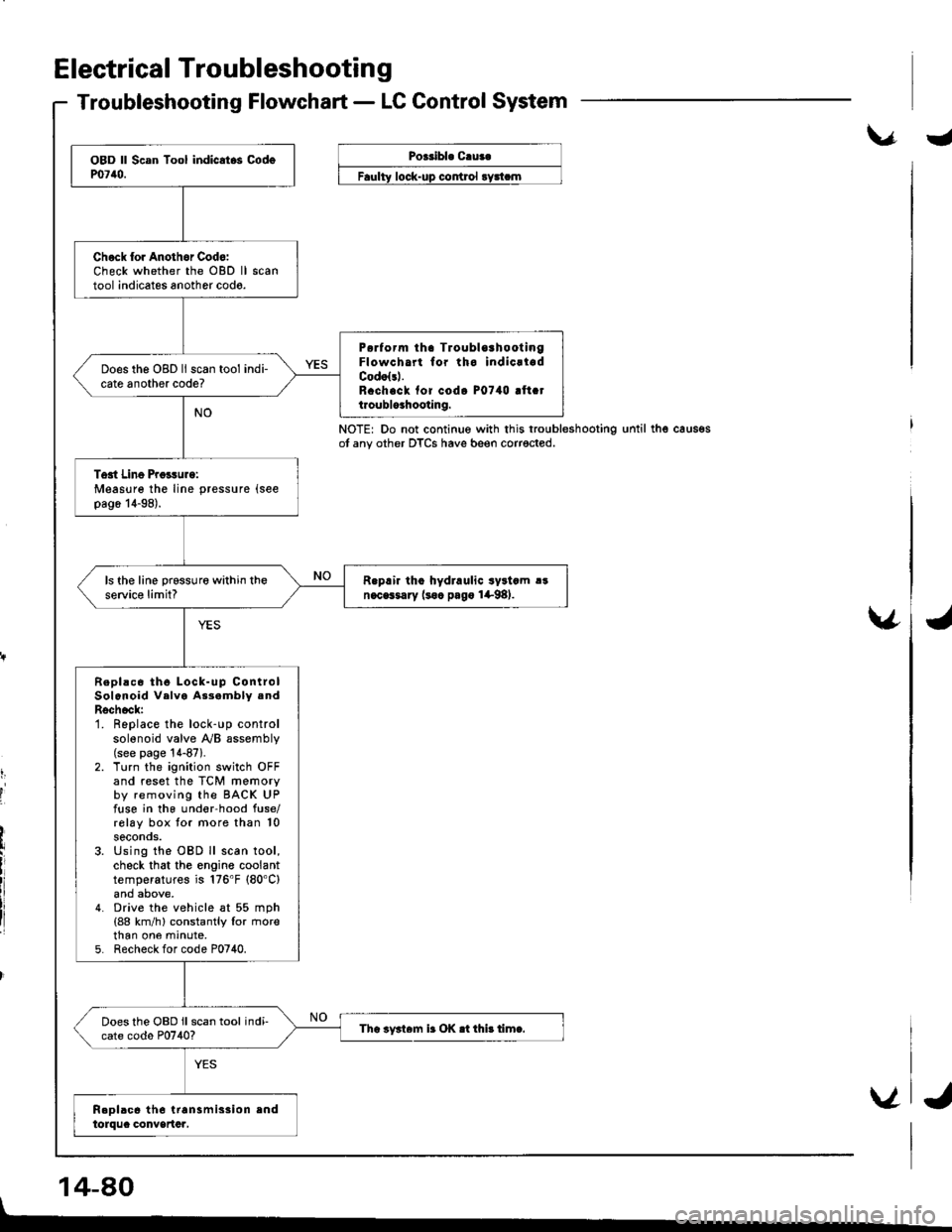
Electrical Troubleshootin g
Troubleshooting Flowchart - LC Control System
\.r.Poeribl. C.ua.
control
NOTE: Do not continue with this troubleshootingot any other DTCS have beeo corrected.until thg caus€s
v
t,
I
'I
14-80
Chock lor Anothor Cod6:Check whether the OBD lltool indicates another codo.
P6rform tha TroublorhootingFlowcha for tho indicrladCodolsl.R.ch.ck fof codo P0740 !ft.tt.oublo3hooting.
Does the OBD ll scan tool indi-cate another code?
Tost Line Proisurg:Measure the line pressure (see
pag6 14-98).
R.prir tho hydraulic syltcm !!n.cGsary (soc pago 1+98).ls the line prsssure within theservic€ limit?
Repl!c6 th6 Lock-up ControlSolenoid Velva As3ambly .ndRschock:1. Replace the lock-up controlsolenoid valve y'y'B assembly(see page '!4-87).
2. Turn the ignition switch OFFand reset the TCM memoryby removing the BACK UPfuse in the und€r-hood fuse/rolay box tor more than 10seconos.3. Using the OBD ll scan tool,check that the engine coolanttemperatures is 176'F (80'C)
4. Drive the vehicle at 55 mph(88 km/h) constantly lor rnorethan one mrnute,5. Recheck for code P0740.
Does the OBD ll scan tool indi-cate codo P0740?Tha iy3t6m ir OK .t thi! timc.
V
I
J
Page 995 of 1681
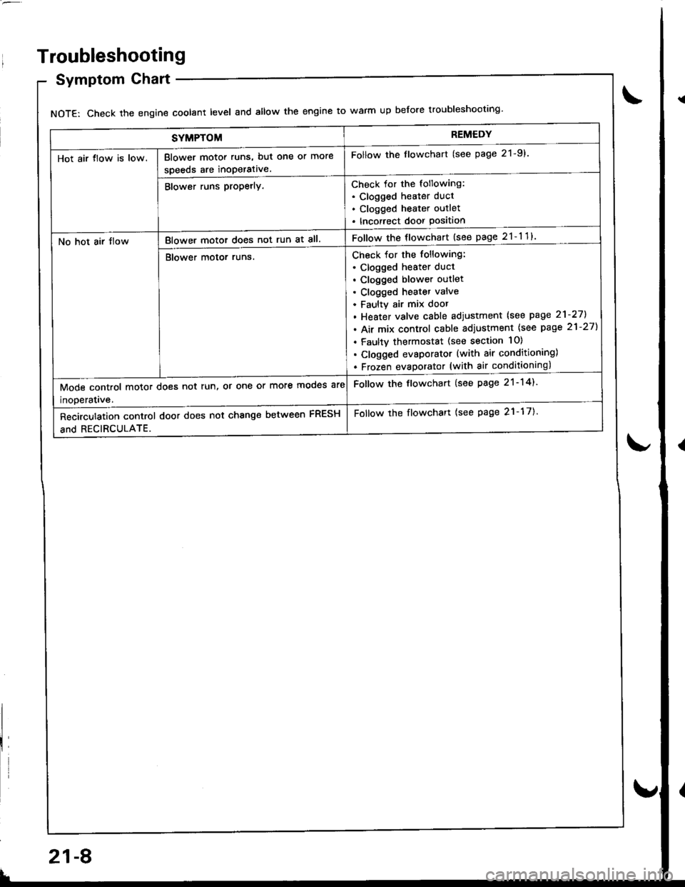
SYMPTOMREMEDY
Hot air tlow is low.Blower motor runs, but one or more
speeds are inoperative.
Follow the flowchart (see page 21-9).
Blower runs propetly.Check for the following:. Clogged heater duct
. Clogged heater outlet
. Incorrect door Position
No hot air tlowBlower motor does not run at all.Follow the flowchart {see page 21-11}
Blower motor runs.Check for the following:
. clogged heater duct
. Clogged blower outlet. Clogged heatet valve
. Faultv air mix door
. Heater valve cable adjustment lsee page 21-27].
. Air mix control cable adiustment {see page 21-27)
. Faulty thermostat (see section 10)
. Clogged evsporator (with air conditioning)
. Frozen evaDorator (with air conditioning)
Mode control motor does not run, or one or more mooes are
inoDeratave.
Follow the flowchart (see page 21-14).
Recirculation control door does not change between FRESH
and RECIRCULATE.
Follow the flowchart {see page 21-17).
Troubleshooting
Symptom Chart
NOTE: Check the engin€ coolant level and allow the engine to warm up before troubleshooting'
21-8
v
Page 1009 of 1681
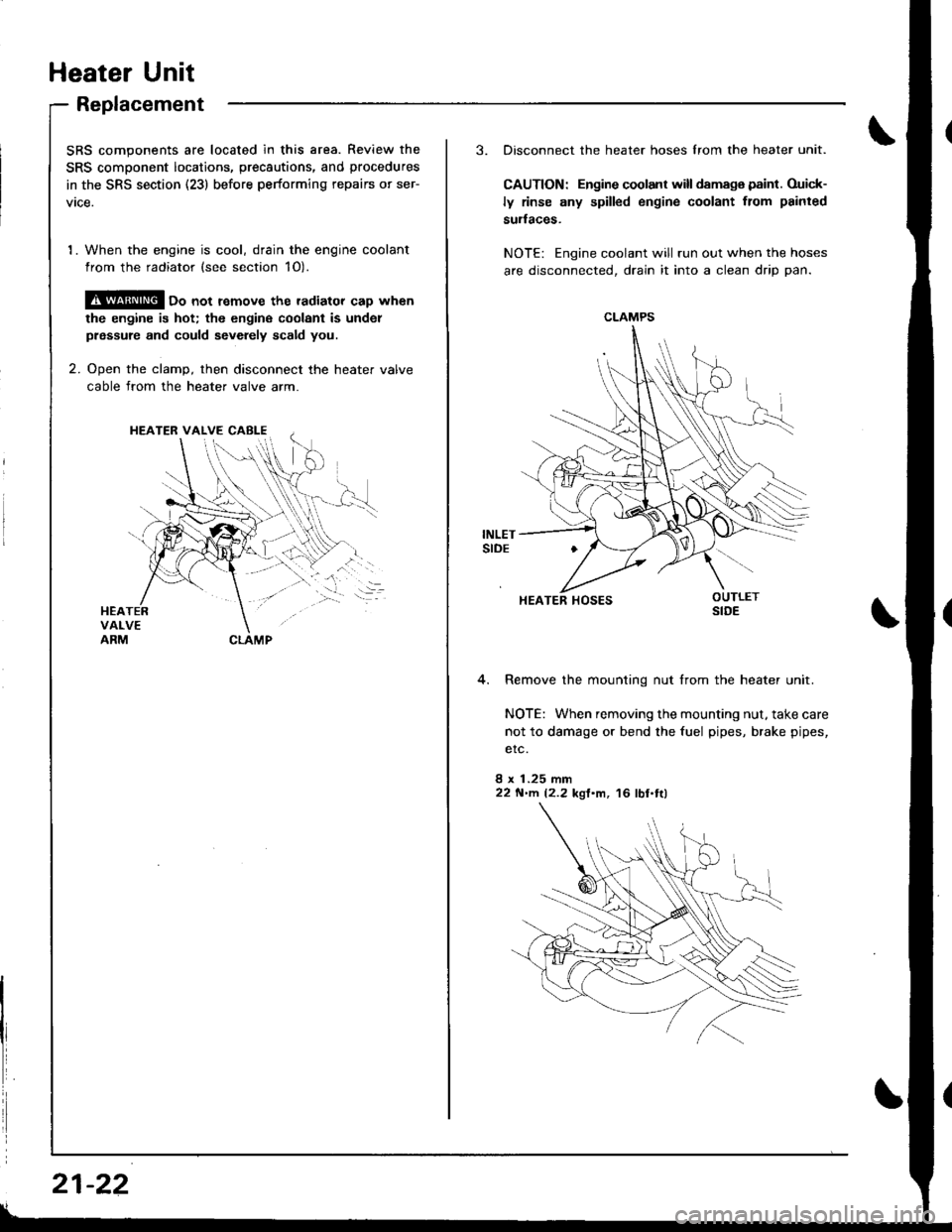
Heater Unit
Replacement
SRS components are located in this area. Review the
SRS component locatio.s, precautions, and procedures
in the SRS section (23) before performing repairs or ser-
vtce.
1. When the engine is cool, drain the engine coolant
from the radiator (see section 1O).
@ oo not remove the radiator cap when
the engine is hot; the engine coolant is undol
prsssure and could sevdely scald you.
2. Ooen the clamD, then disconnect the heater valve
cable from the heater valve arm.
HEATER VALVE CABI-E
I
i
21-22
3. Disconnect the heater hoses lrom the heater unit.
CAUTION: Engine coolant will damaga paint. Ouick-
ly rinse any spilled engine coolant from painted
sudaces.
NOTE: Engine coolant will run out when the hoses
are disconnected, drain it into a clean drip pan.
4. Remove the mounting nut from the heater unit.
NOTE: When removing the mounting nut, take care
not to damage or bend the fuel pipes, brake pipes,
etc.
8 x 1.25 mm22 N'llt. 12.2 kgl'm, 16 lbl.tl)
CLAMPS
HEATER HOSES
Page 1010 of 1681
.J
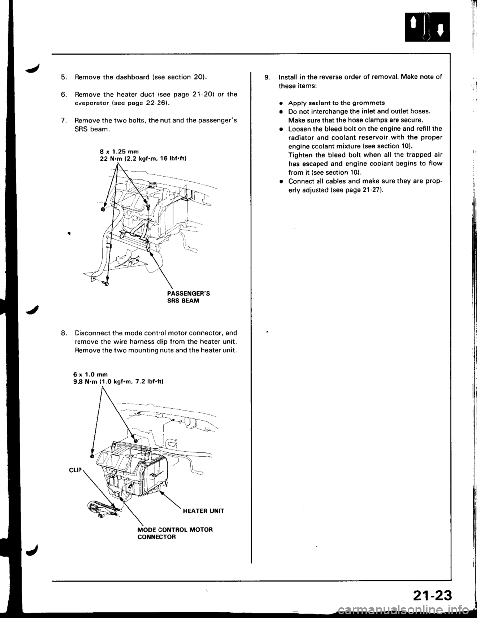
5.
6.
7.
8.
Remove the dashboard (see section 2O).
Remove the heater duct (see page 21 20) or the
evaporator lsee page 22-261.
Remove the two bolts, the nut and the passenger's
SRS beam.
PASSENGER'SSRS BEAM
Disconnect the mode control motor connector. and
remove the wire harness clip from the heater unit.
Remove the two mounting nuts and the heater unit.
6 x 1.0 mm9.8 N.m (1.0 kgf.m, 7.2 lbf.ftl
I r 1.25 mm22 N.m 12.2 kgf.m, 16 lbf'ft)
Il
I
I
lnstall in the reverse order of removal. Make note of
these items:
. Apply sealant to the grommets
. Do not interchange the inlet and outlet hoses.
Make sure that the hose clamps are secure.
. Loosen the bleed bolt on the engine and refill the
radiator and coolant reservoir with the proper
engine coolant minure (see section 10).
Tighten the bleed bolt when all the trapped air
has escaped and engine coolant begins to flow
from it (see section 10).
. Connect all cables and make sure they are prop-
erly adjusted (see page 2'l-271.
;!
i
21-23
Page 1030 of 1681
Troubleshooting
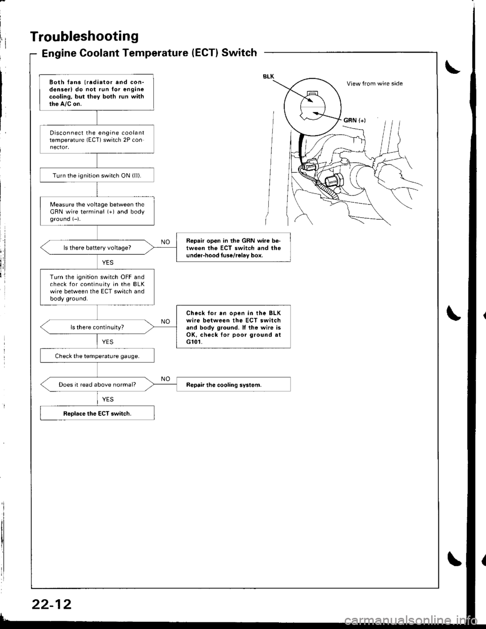
Engine Coolant Temperature(ECT}Switch
Both fans (radiator and con-denserl do not run for enginecooling, but they both run withthe A,/c on.
Disconnect the engine coolanttemperature lECT) switch 2P con
Turn the ignirion switch ON ( ll).
Measure the voltage between theGRN wire terminal (+) and bodyground (-)-
Repair open in the GRN wire b€-tween the ECT switch and theunder-hood luse/rel6v box,ls there battery voltageT
Turn the ignition switch OFF andcheck for continuity in the BLKwire between the ECT switch andbody ground.
Check for en ooen in the BLKwire between the ECT switchand body ground. ll th. wire isOK, check lor poor ground atG101.
ls there continuity?
Check the temperature gauge.
Does it read above normal?
View from wire side
GRN (+)
Page 1073 of 1681
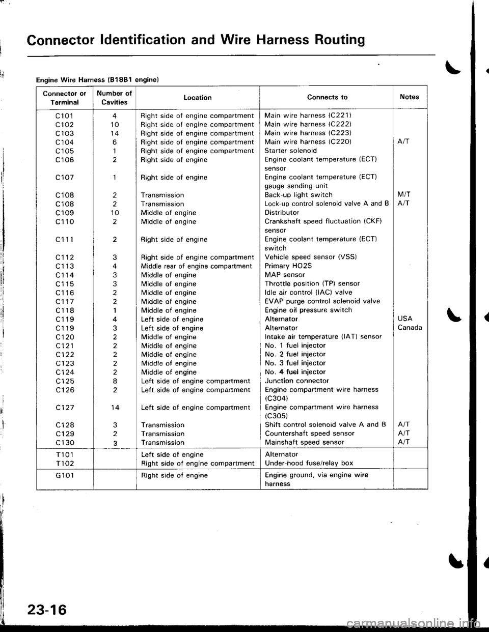
Connector ldentification and Wire Harness Routing
Connectot or
Terminal
Numbel of
CavitiesLocationConnects toNotes
c'to 1
c102
c103
c'1 04
c105
c106
c 107
c108
c108
c109
c110
c112
c113
c'r 14
c115
c116
c117
c118
ct'l9
c119
c120
c121
c122
c124
c't 26
c127
c128
c129
c130
c111
4
10
14
6
I
1
2
2
10
2
3
2
J
4
3
3
2
2
I
3
2
2
2
2
2
I
2
14
Right side of engine compartment
Right side of engine compartment
Right side ot engine compartment
Right side of engine compartment
Right side oI engine compartment
Right side of engine
Right side of engine
Transmission
Transmission
Middle ot engine
Middle ot engine
Right side of engine
Right side of engine compartment
Middle rear of engine compartment
N4iddle of engine
N4iddle ol engine
Middle oI engine
Nliddle ot engine
Middle of engine
Lelt side of engine
Left side of engine
Middle of engine
Middle oI engine
Middle of engine
Middle of engine
Middle ot engine
Left side of engine compartment
Lelt side ot engine compartment
Left side of engine compartment
Transmission
Transmission
Transmission
Main wire harness (C221)
Main wire harness (C222)
Main wire harness 1C223)
lvlain wire harness (C220)
Starter solenoid
Engine coolant temperature (ECT)
sensor
Engine coolant temperature (ECT)
gauge sending unit
Back-up light switch
Lock-up control solenoid valve A and B
Distributor
Crankshatt speed fluctuation (CKF)
sensor
Engine coolant temperature (ECT)
switch
Vehicle speed sensor (VSS)
Primary HO2S
MAP sensor
Throttle position (TP) sensor
ldle air control (lAC) valve
EVAP purge control solenoid valve
Engine oil pressure switch
Alternator
Alternator
lntake air temperature (lAT) sensor
No. 1 fuel injector
No. 2 fuel injector
No. 3 fuel injector
No. 4 fu€l injector
Junction connector
Engine compartment wire harness
(c304)
Engine compartment wire harness
(c30s)
Shift control solenoid valve A and B
Countershaft speed sensor
lvlainshaft speed sensor
M/T
NT
USA
Canada
Afi
Afi
T101
T102
Left side oI engine
Right side of engine compartment
Alternator
Under hood fuse/relay box
G'1 01Right side oI engineEngine ground. via engine wire
harness
Engine Wire Harness (B188l enginel
23-16