Transmission HONDA INTEGRA 1998 4.G Workshop Manual
[x] Cancel search | Manufacturer: HONDA, Model Year: 1998, Model line: INTEGRA, Model: HONDA INTEGRA 1998 4.GPages: 1681, PDF Size: 54.22 MB
Page 629 of 1681
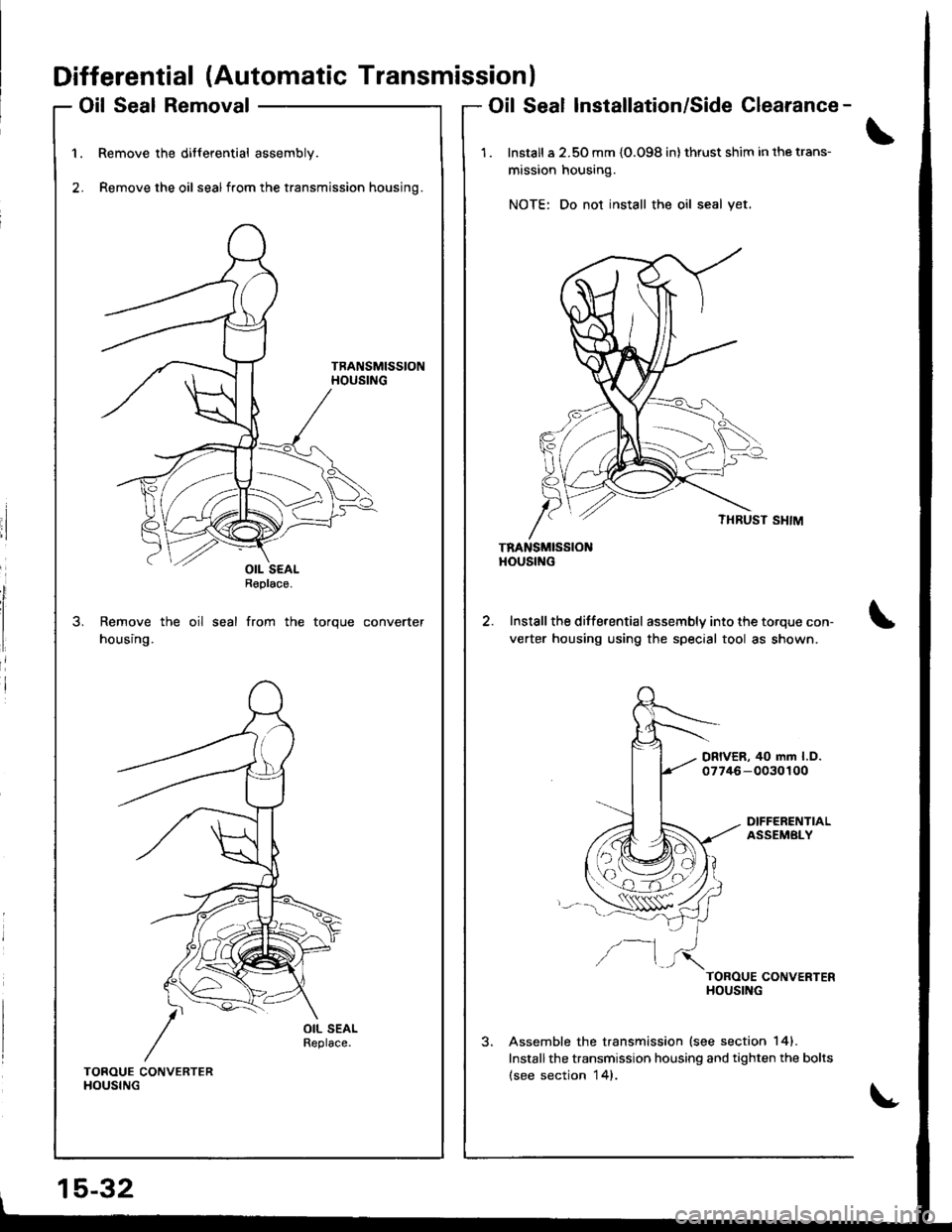
Differential (Automatic Transmissionl
Oil Seal Removal
Remove the differential assembly.
Remove the oil sealfrom the transmission housing.
Remove the oil seal from the torque converter
housing.
Oil Seal Installation/Side Clearance-
1 . Install a 2.50 mm {O.O98 in} thrust shim in the trans-
mission housing.
NOTE: Do not install the oil seal yet.
TRANSMISSIONHOUStf{G
Install the differential assembly into the torque con-
verter housing using the special tool as shown.
DRIVER, 40 mm l.D.07746-0030100
DIFFERENTIALASSEMBLY
/--1TOROUE CONVERTERHOUSING
Assemble the transmission lsee section 141.
Installthe transmission housing and tighten the bolts(see section 14).TOROUE CONVERTERHOUSING
15-32
OIL SEALReplace.
Page 630 of 1681
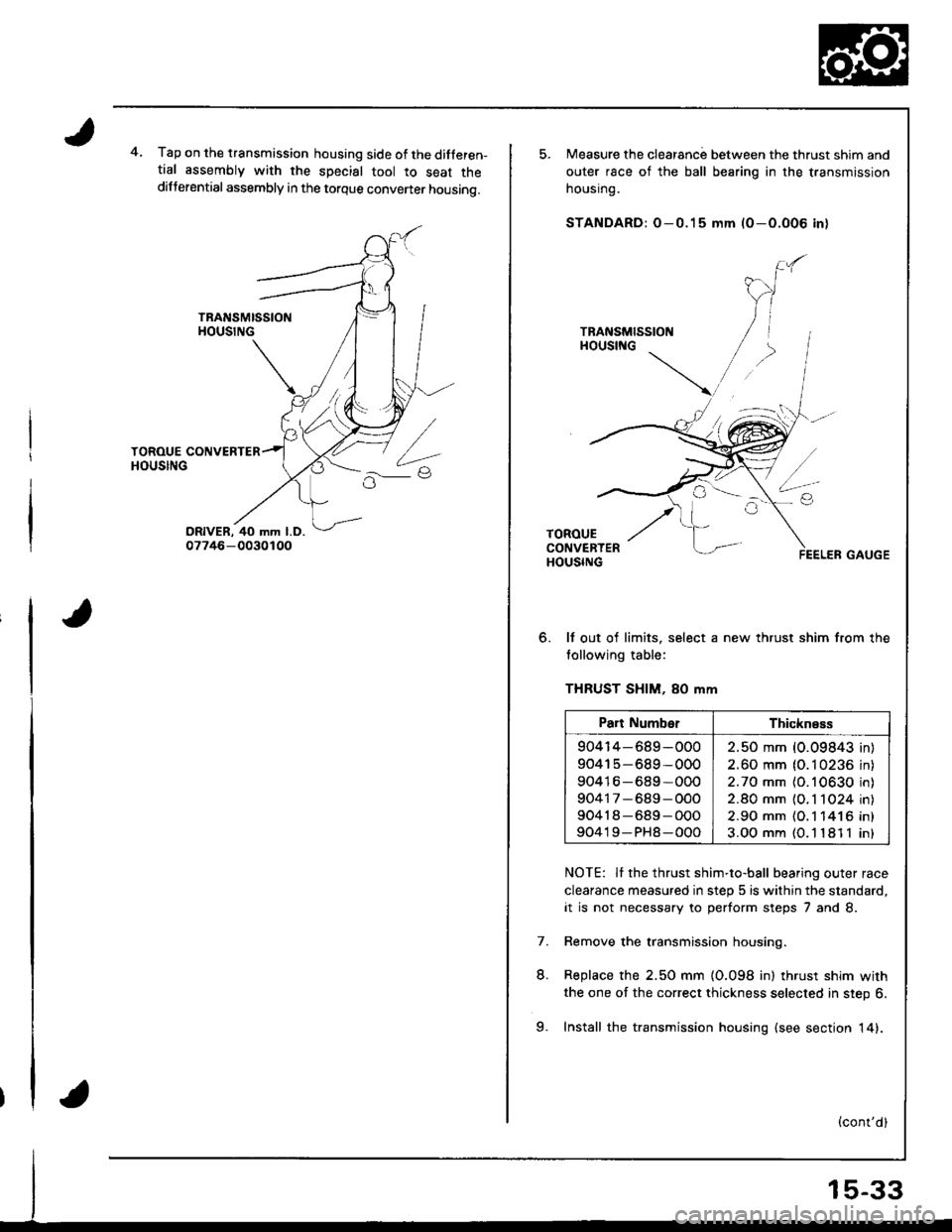
4.Tap on the transmission housing side of the ditferen-tial assembly with the special tool to seat thedifferential assembly in the torque convener housing.
o.
Measure the clearanc; between the thrust shim and
outer race of the ball bearing in the transmission
nousrng.
STANDARD: O-0.15 mm (O-O.O06 in)
It out of limits. select a new thrust shim from the
tollowing table:
THRUST SHIM, 80 mm
NOTE: Il the thrust shim-to-ball bearing outer race
clearance measured in step 5 is within the standard,
it is not necessary to perform steps 7 and 8.
Remove the transmission housing.
Replace the 2.50 mm {0.098 in) thrust shim with
the one of the correct thickness selected in step 6.
Install the transmission housing (see sectjon 14).
7.
L
Part NumberThickness
904r4-689-000
90415-689-000
90416-689*000
90417-689-OOO
90418-689-O00
90419-PH8-000
2.50 mm (0.09843 in
2.60 mm (0.10236 in
2.70 mm (O.10630 in
2.80 mm {O. 1 1O24 in
2.90 mm {O.1 141 6 in
3.OO mm (O. l '181 1 in
9.
Page 631 of 1681
Differential (Automatic Transmission)
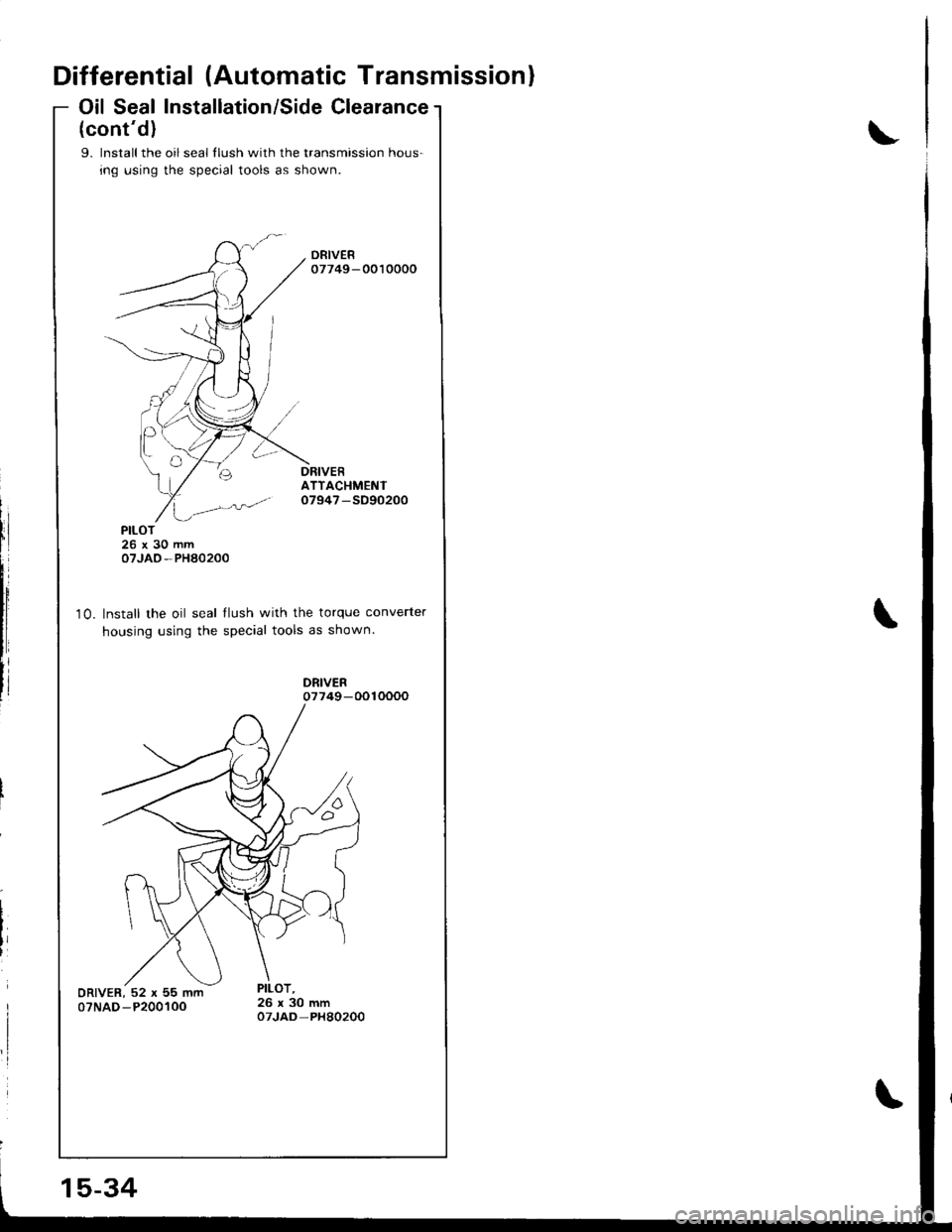
Oil Seal Installation/Side Clearance
(cont'd)
9. lnstall the oil seal llush with the transmission hous-
ing using the special tools as shown.
ATTACHMENTo7947 -SD90200
10.
PILOT26x30mmoTJAO-PHA0200
Install the oil seal llush with the torque converter
housing using the special tools as shown.
15-34
Page 634 of 1681
t
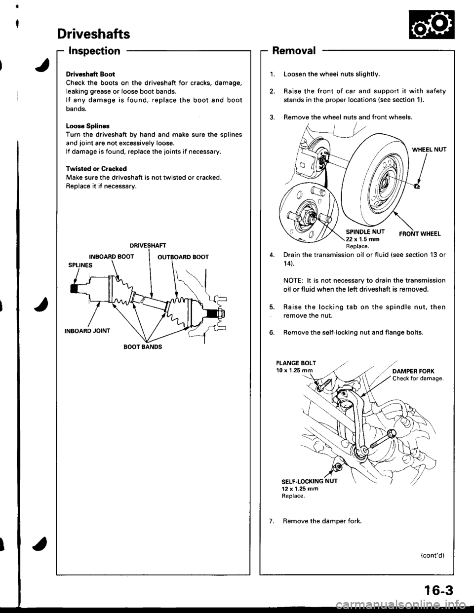
Driveshafts
Inspection
Drivcshatt Boot
Check the boots on the driveshaft tor cracks. damage,
leaking grease or loose boot bands.
lf any damage is found, replace the boot and boot
oanos.
Looso SplineE
Turn the driveshaft by hand and moke sure the splines
and joint are not excessively loose.
lf damage is found, replace the joints if necessary.
Twisled or Crscked
Make sure the driveshaft is not tlvisted or cracked.
Replace it if necessary.
BOOT BANDS
1.Loosen the wheel nuts slightly,
Raise the front of ca. and support it with safety
stands in the prope. locations {see section 1).
Remove the wheel nuts and front wheels.
5.
Drain the transmission oil or fluid (see section 13 or
14t.
NOTE: lt is not necessary to drain the transmission
oil or fluid when the left driveshaft is removed.
Raise the locking tab on the spindle nut, then
remove the nut.
6. Remove the self-locking nut and flange bolts.
FLANGE BOLT'10 x 1.25
SELF.LOCKING NUT
12 x 1.25 mmReplace.
(cont'd)
Replace.
7. Remove the damoer fork.
Removal
6-3
Page 646 of 1681
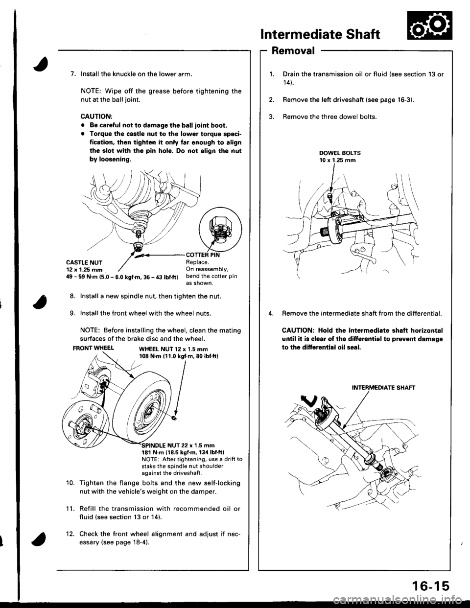
Intermediate Shaft
Removal
Drain the transmission oil or fluid {see section 13 or
14t.
Remove the left driveshaft (see page 16-3).
Bemove the three dowel bolts.
Remove the intermediate sh8ft from the differential.
CAUTION: Hold the intermediate shaft horizontal
until it is clear ot th6 difforantirl to prevont damage
to thc ditf€rential oil seal.
7. Install the knuckle on the lower arm.
NOTE: Wipe off the grease before tightening the
nut at the ball joint.
CAUTION:
. Be careful not to damago the ballioint boot.
. Torque the castle nut to tho low€r torque speci-
tication, then tighten it only lar onough to align
th6 slot whh tho pin hols. Do not align the nut
by loosening.
,.<__coTTEF PtNCASTLE NUT12 x 1.25 mm49 - 59 N.m {5.0 - 5.0 kgf.m, 36 - t3 lbl.ft)
Beplace.On reassembly,bend the cotter pin
8. Install a new spindle nut, then tighten the nut.
9. Installthe front wheel with the wheel nuts.
NOTE: Before installing the wheel, clean the mating
surfaces of the brake disc and the wheel.
FRONT WHEELWH€EL NUT 12 x 1.5 mm108 N.m (11.0 kgt m,80lbf ft)
10.
NUT 22 x '1.5 mm181 N m 118.5 kgl.m, 134lbtftlNOTE: After tightening, use a drift tostake the spindle nut shoulderagainst the driveshatt.
Tighten the flange bolts and the new self-locking
nut with the vehicle's weight on the damper.
Refill the transmission with recommended oil or
fluid (see section 13 or 14).
11.
12. Check the front wheel alignment and adjust if nec-
essary (see page 18-4).
INTERMCOIATE SHAFT
16-15
Page 767 of 1681
1.
8.
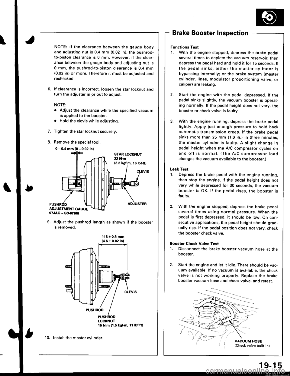
NOTE: lf the clearance between the gauge body
and adjusting nut is 0.4 mm (0.02 in), the pushrod-
to-piston clearance is 0 mm. However, if the clear-
ance between the gauge body and adjusting nut is
0 mm, the pushrod-to-piston clearance is 0.4 mm(0.02 in) or more. Therefore it must be adjusted and
rechecked.
lf clearance is incorrect, loosen the star locknut and
turn the adjuster in or out to adjust.
NOTE:
. Adjust the clearance while the specified vacuum
is applied to the booster.
. Hold the clevis while adjusting.
Tighten the star Iocknut securely.
Remove the special tool.
0 - o.il mm l0 - 0.02 inl
Brake Booster Inspection
Functions Tgst
1. With the engine stopped, depress the brake pedal
several times to deplete the vacuum reservoir, then
depress the pedal hard and hold it for 15 seconds. ll
the pedal sinks, either the master cylinder is
bypassing internally; or the brake system (master
cylinder, lines, modulator proportioning valve, orcaliper) are leaking.
Start the engine with the pedal depressed. lf thepedal sinks slightly, the vacuum booster is operat-
ing normally. lf the pedal height does not vary, the
booster or check valve is faulty.
With the engine running, depress the brake pedal
lightly. Apply just enough pressure to hold back
automatic transmission creep, lf the brake pedal
sinks more than 25 mm (1.0 in.) in three minutes,
the master cylinder is faulty. A slight change inpedal height when the A,,/C compressor cycles on
and off is normal. (The A/C compressor load
changes the vacuum available to the booster.)
Leak Test
1. Depress the brake pedal with the engine running,
then stop the engine. lf the pedal height does not
vary while depressed for 30 seconds, the vacuum
booster is OK. lf the pedal rises, the booster is
fau lty.
2. With the engine stopped, depress the brake pedal
several times using normal pressure. When thepedal is first depressed, it should be low. On con-
secutive applications, the pedal height should grad-
ually rise. lf the pedal position does not vary, check
the booster check valve.
Boostor Ch€ck Valve T6st
1. Disconnect the brake booster vacuum hose at the
booster,
Start the engine and let it idle. There should be vac-
uum available. It no vacuum is available. the check
valve is not working properly. Replace the brake
booster vacuum hose and check valve, and retest.
VACUUM HOSE(Check valve built-in)
STAR LOCKNUT22 t{.m12.2 ksl.m, 16lbf.ftl
cLEVtS
ADJUSTER
ADJUSTMENT GAUGE07JAG - SD40t00
9. Adjust the pushrod length as shown if the booster
is removed.
1161 0.5 mm14.61 0.02 inl
PUSHRODLOCKNUT15 N m 11.5 kgf m, 11 lbf'ftl
10. Instali the master cylinder.
Page 1053 of 1681
J
A/G Compressor Belt
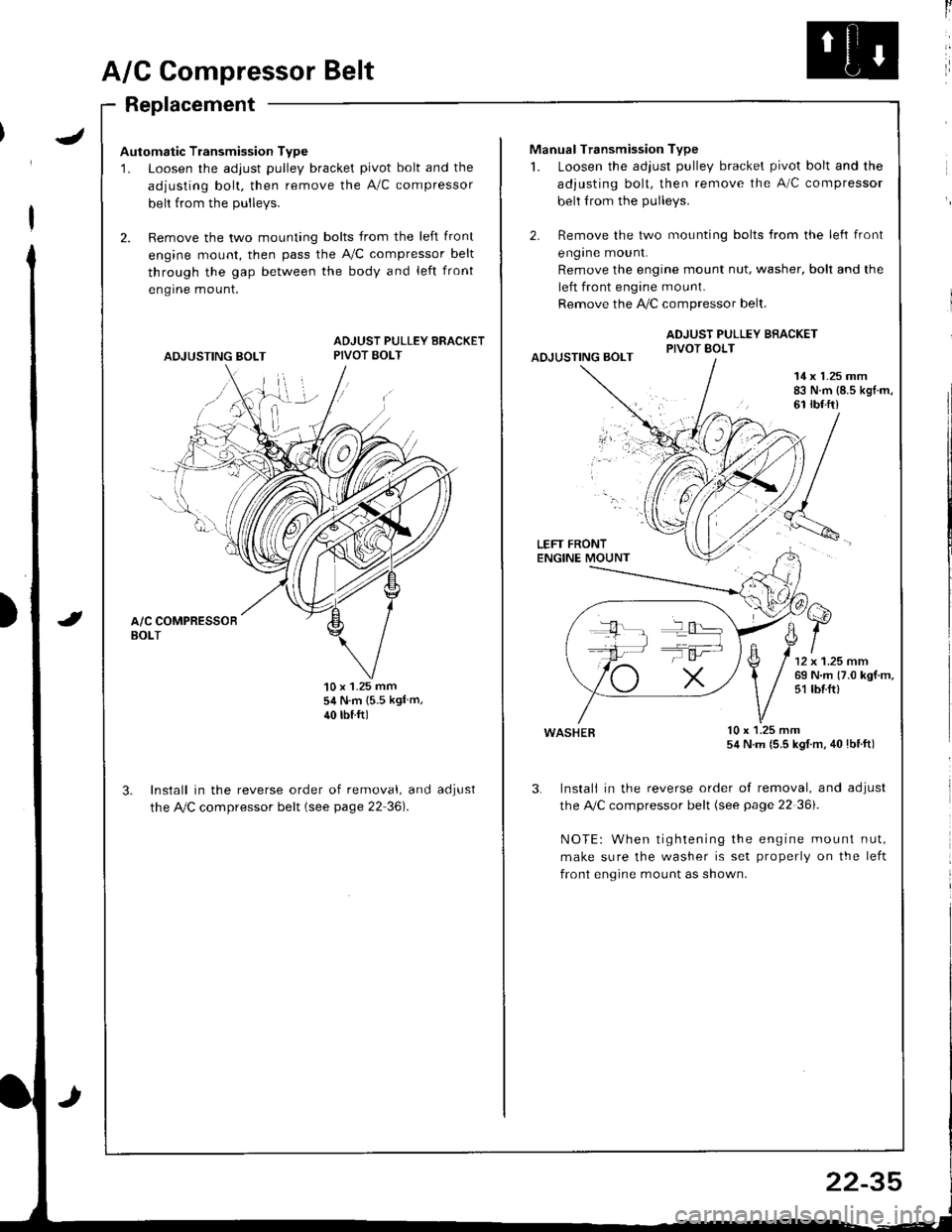
Replacement
Automatic Transmission Type
1. Loosen the adjust pulley bracket pivot bolt and the
adjusting bolt. then remove the A/C compressor
belt from the Dullevs.
2. Remove the two mounting bolts from the left front
engine mount, then pass the A,/C compressor belt
through the gap between the body and left front
engrne mount.
ADJUSTING BOLT
ADJUST PULLEY BRACKETPIVOT BOLT
'10 x 1.25 mm54 N.m {5.5 kgl m,
40 rbtftl
Install in the reverse order of removal, and
the Ay'C compressor belt (see page 22 36).
aoJUsI
ll
Manual Transmission Type
1. Loosen the adjust pulley bracket pivot bolt and the
adjusting bolt, then remove the A/C compressor
belt from the pulleys.
2. Remove the two mounting bolts from the left front
engrne mount.
Remove the engine mount nut, washer, bolt and the
left front engine mount.
Remove the !i/C compressor belt.
ADJUST PULLEY BRACKETPIVOT BOLTAOJUSTING BOLT
14 x 1.25 mm83 N.m {8.5 kgl.m,61 rbf.ft)
LEFT FRONTENGINE MOUNT
wasHEB lu x l.z5 mm54 N.m (5.5 kgl m, 40lbtft)
3. Instali in the reverse order of removal, and adjust
the A,/C compressor belt (see page 22 36i.
NOTE: When tightening the engine mount nut,
make sure the washer is set properly on the left
front engine mount as shown.
T':
22-35
Page 1071 of 1681
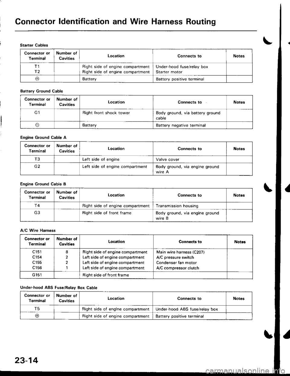
Connector ldentification and Wire Harness Routing
Starter Cables
Connectol ot
Terminal
Numbel of
CavitiesLocationConnects toNotes
Tl
r2
Right side of engine compartment
Right side oI engine compartment
Under-hood Iuse/relay box
Starter motor
oBatteryBattery positive terminal
Battely Ground Cable
Connector ol
Terminal
Numbel of
CavitiesLocationConnects toNotes
Right lront shock towerBody ground, via battery ground
caore
oBatteryBattery negative terminal
Engine Ground Cable A
Connector ol
Terminal
Number ol
CavitiesLocationConnects toNotes
T3Left side of engineValve cover
c2Left side oI engine compartmentBody ground. via engine ground
Engine Ground Cable B
Connector ol
Terminal
Numbel of
CavitiesLocationConnects toNot€s
r4Right side of engine compartmentTransmission housing
Right side of front frameBody ground, via engine ground
wire B
A/C Wire Harness
Connector or
Terminal
Number of
CavitiesLocationConnects toNotos
c 151
cl54
c156
8
2,l
Righr side of engine compartment
Left side of engine companment
Left side of engine compartment
Left side of engine compartment
Main wire harness (C207)
A,/C pressure switch
Condenser fan motor
ly'C compressor clutch
Right side of front frame
Under-hood ABS Fuse/Relav Box Cable
Connector or
Telminal
Number of
CavitiesLocationConnects toNotes
T5Right side o'f engine compartmentUnderhood ABS fuse/relay box
@Right side oI engine compaftmentBattery positive terminal
23-14
Page 1073 of 1681
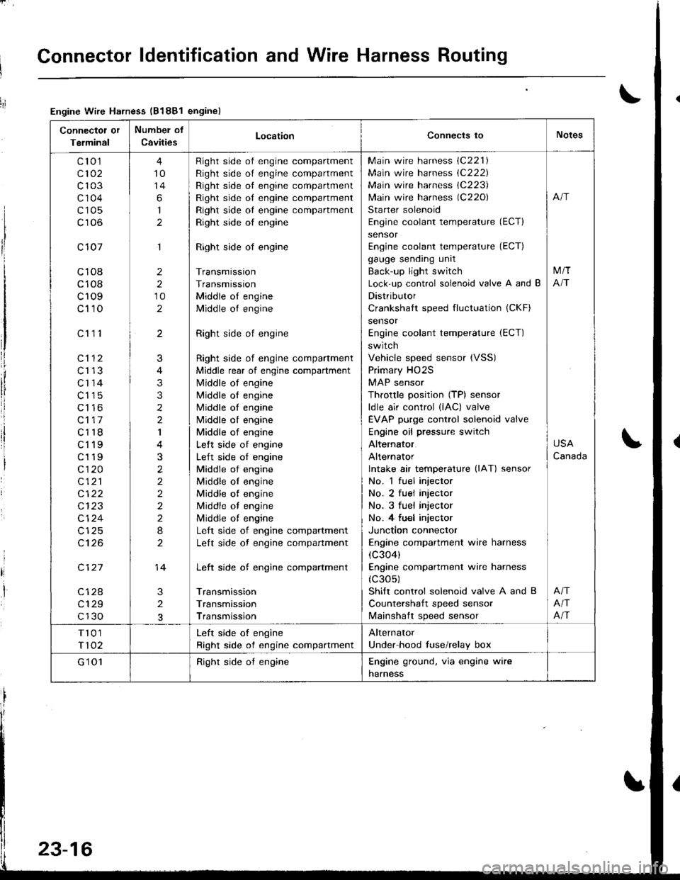
Connector ldentification and Wire Harness Routing
Connectot or
Terminal
Numbel of
CavitiesLocationConnects toNotes
c'to 1
c102
c103
c'1 04
c105
c106
c 107
c108
c108
c109
c110
c112
c113
c'r 14
c115
c116
c117
c118
ct'l9
c119
c120
c121
c122
c124
c't 26
c127
c128
c129
c130
c111
4
10
14
6
I
1
2
2
10
2
3
2
J
4
3
3
2
2
I
3
2
2
2
2
2
I
2
14
Right side of engine compartment
Right side of engine compartment
Right side ot engine compartment
Right side of engine compartment
Right side oI engine compartment
Right side of engine
Right side of engine
Transmission
Transmission
Middle ot engine
Middle ot engine
Right side of engine
Right side of engine compartment
Middle rear of engine compartment
N4iddle of engine
N4iddle ol engine
Middle oI engine
Nliddle ot engine
Middle of engine
Lelt side of engine
Left side of engine
Middle of engine
Middle oI engine
Middle of engine
Middle of engine
Middle ot engine
Left side of engine compartment
Lelt side ot engine compartment
Left side of engine compartment
Transmission
Transmission
Transmission
Main wire harness (C221)
Main wire harness (C222)
Main wire harness 1C223)
lvlain wire harness (C220)
Starter solenoid
Engine coolant temperature (ECT)
sensor
Engine coolant temperature (ECT)
gauge sending unit
Back-up light switch
Lock-up control solenoid valve A and B
Distributor
Crankshatt speed fluctuation (CKF)
sensor
Engine coolant temperature (ECT)
switch
Vehicle speed sensor (VSS)
Primary HO2S
MAP sensor
Throttle position (TP) sensor
ldle air control (lAC) valve
EVAP purge control solenoid valve
Engine oil pressure switch
Alternator
Alternator
lntake air temperature (lAT) sensor
No. 1 fuel injector
No. 2 fuel injector
No. 3 fuel injector
No. 4 fu€l injector
Junction connector
Engine compartment wire harness
(c304)
Engine compartment wire harness
(c30s)
Shift control solenoid valve A and B
Countershaft speed sensor
lvlainshaft speed sensor
M/T
NT
USA
Canada
Afi
Afi
T101
T102
Left side oI engine
Right side of engine compartment
Alternator
Under hood fuse/relay box
G'1 01Right side oI engineEngine ground. via engine wire
harness
Engine Wire Harness (B188l enginel
23-16
Page 1075 of 1681
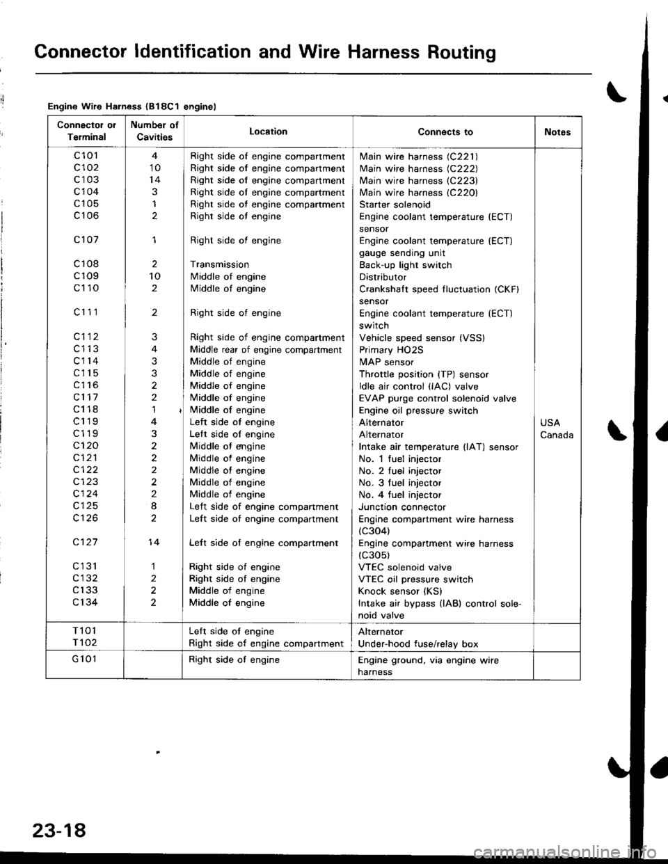
Connector ldentification and Wire Harness Routing
Engine Wire Harness (B18Cl enginel
Connectol ol
Terminal
Number of
CavitiesLocationConnects toNotes
c 101
c102
c103
c104
c105
c106
c101
c108
cr09
c110
c'r 11
cl12
c1't3
c114
c115
c116
cl17
c118
c119
c119
c120
cI2'l
cl24
c126
c127
cl31
c132
c133
c134
10
14
3
1
2
1
2
10
2
'I
3
2
2
2
I
1
2
2
?
3
2
14
Right side of engine compartment
Right side of engine compartment
Right side of engine compartment
Right side ol engine compartment
Right side of engine compartment
Righr side oI engine
Right side of engine
Transmission
Middle of engine
Middle of engine
Right side of engine
Right side of engine compartment
Middle rear of engine compartment
Middle of engine
Middle of engine
Middle of engine
Middle of engine
i/iddle of engine
Left side ot engine
Lelt side ot engine
Middle ot engine
Middle of engine
Middle of engine
Middle of engine
Middle of engine
Left side of engine companment
Left side of engine compartment
Lelt side of engine compartment
Right side of engine
Right side of engine
Middle of engine
Middle of engine
lvlain wire harness (C221 )
Main wire harness {C222)
Main wire harness (C223)
Main wire harness (C220)
Starter solenoid
Engine coolant temperature (ECT)
sensor
Engine coolant temperature (ECT)
gauge sending unit
Back-up light switch
Distributor
Crankshalt speed fluctuation (CKFI
sensor
Engine coolant temperature {ECT)
switch
Vehicle speed sensor (VSS)
Primary HO2S
MAP sensor
Throttle position {TP) sensor
ldle air control (lAC) valve
EVAP purge control solenoid valve
Engine oil pressure switch
Alternator
Alternator
Intake air temperature llAT) sensor
No. 1 fuel injector
No. 2 fuel injector
No. 3 tuel injector
No. 4 tuel injector
Junctron connector
Engine compartment wire harness(c304)
Engine companment wire harness(c30s)
VTEC solenoid valve
VTEC oil pressure switch
Knock sensor (KS)
Intake air bypass {lAB) control sole-
noid valve
USA
Canada
T101
r 102
Left side ot engine
Right side of engine compartment
Alternator
Under-hood fuse/relay box
G 101Right side of engineEngine ground, via engine wire
naaness
23-18