torque HONDA INTEGRA 1998 4.G Manual Online
[x] Cancel search | Manufacturer: HONDA, Model Year: 1998, Model line: INTEGRA, Model: HONDA INTEGRA 1998 4.GPages: 1681, PDF Size: 54.22 MB
Page 984 of 1681
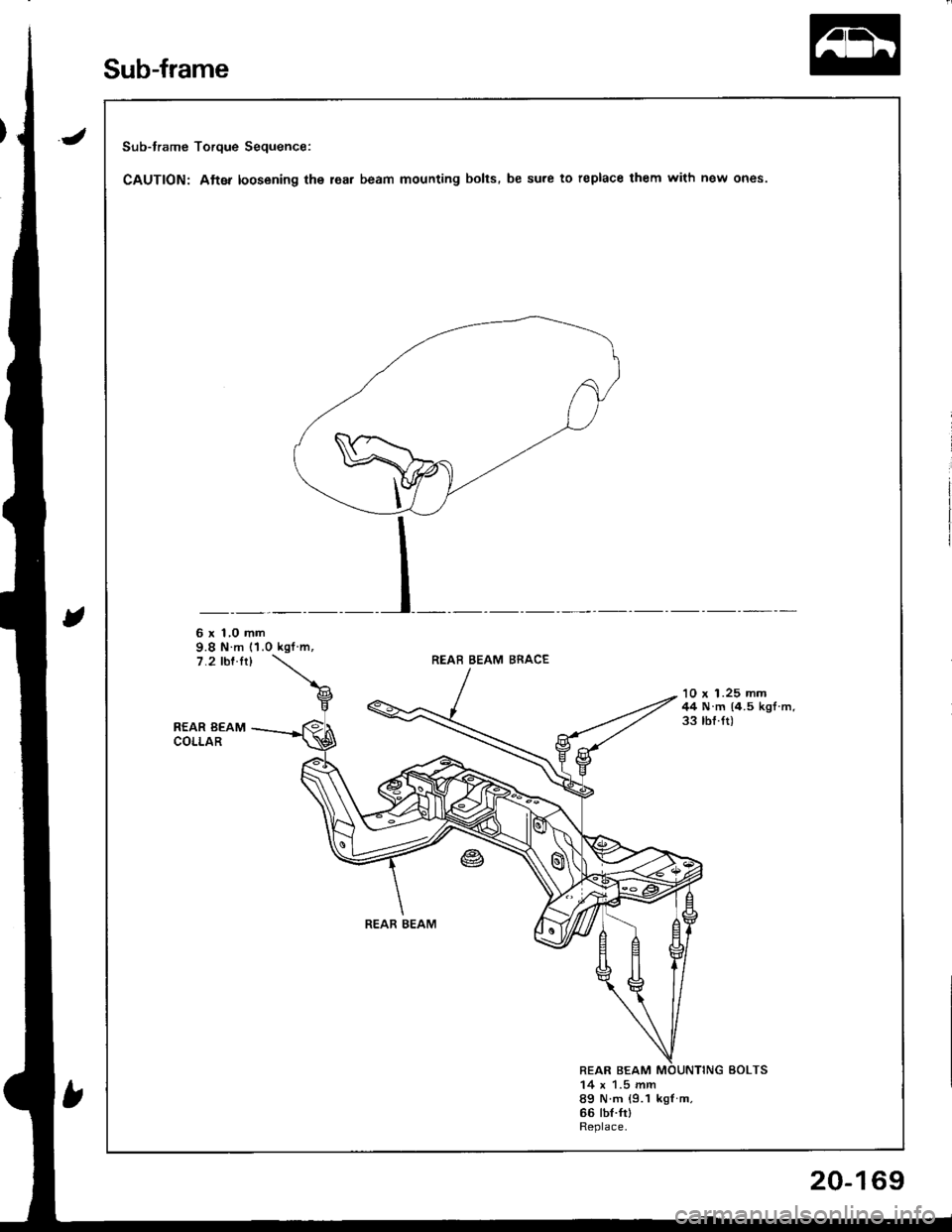
Sub-frame Torque Sequence:
CAUTION: Atter loosening the lea. beam mounting bolts. be sure to replace them with new ones.
6 x 1,0 mm9.8 N m (1.0 kgf m,7.2 rbf.ft)REAB BEAM BRACE
REAR BEAMCOLLAR
'10 x 1.25 mm44 N.m (4.5 kgl.m.33 tbf.ft)
REAR BEAM
REAR BEAM14 x 1.5 mm89 N m {9.1 kgf m.66 tbt.frlReplace.
Sub-frame
20-169
Page 1135 of 1681
Starting System
Starter Test (cont'dl
Check Cranking rpmr
Engine speed during cranking should be above 1OO rpm.
lJ speed is too low, check for:
a Loose batlery or starter terminals
a Excessively worn starter brushes
a Open circuit in commutator segments
a Dirty or damaged helical spline or drive gear
a Defective drive gear overrunning clutch
Check Starter Disengagement:
Press the clutch pedal all the way in (M/T), turn rhe igni
tion switch to "lll" and release to "11".
The starter drive gear should disengage from the flywheel
or torque converter ring gear when you release the key.
It the drive gear hangs up on the flywheel or torque con-
verter ring gear, check for:
a Solenoid plunger and switch mallunction
a Dirty drive gear assembly or damaged overrunning
clutch
5. Check for an open in the BLK/WHT wire circuit be
tween the starter and ignition switch, and con-
necrors,
6. Check the ignition switch (see page 23-71).
7. On cars with automatic transmission, check the A/Tgear position switch (neutral position switch) and
connector. On cars with manualtransmission, check
the starter cut relay, clutch interlock switch, and
connectors.
NOTE: Check the No. 42 (40 A) fuse in the under,hoodfuse/relay box for the starter cut relay.
Check Jor Wear and Damage:
The starter should crank the engine smoothly and stead,ily. lf the starter engages, but cranks the engine errati
cally, remove it. Inspect the starter, drive gear, andllywheel or torque converter ring gear lor damage.
a Check the drive gear overrunning clutch for binding
or slipping when the armature is rotated with the drivegear held. Replace the gears i{ damaged.
Check CJanking Voltage and Current Draw:
Cranking voltage should be no less than 8.O volts.
Current draw should be no more than * amperes.* 1.2 kW: 27O A
1 .4 kW: 360 A
It cranking voltage is too low, or current draw too high,check for:
a Dead or low charged batterya Open circuit in starter armature commutator segmentsa Starter armalure dragging
a Shorted armature windinga Excessive drag in engine
Page 1142 of 1681
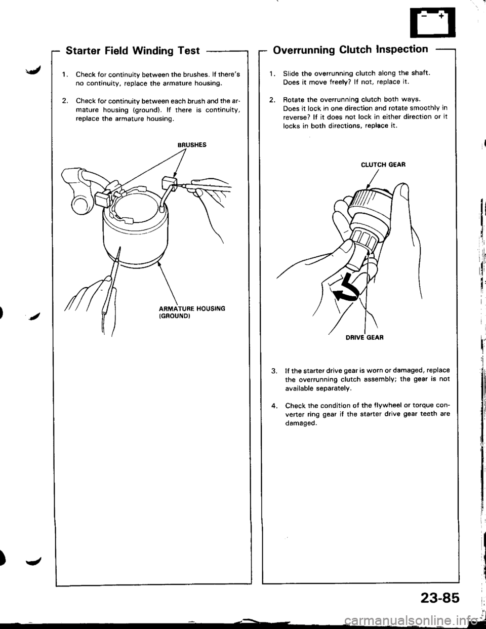
BRUSHES
Startel Field Winding Test
Check for continuity between the brushes. lf there's
no continuity. replace the armature housing.
Check for continuily between each brush and the ar-
mature housing (ground). lf there is continuity,
replace the armature housing.
Overrunning Clutch InsPection
Slide the overrunning clutch along the shaft.
Does it move freely? It not, replace it.
Rotate the overrunning clutch both ways.
Does it lock in one direction and rotate smoothly in
reverse? It it does not lock in either direction or it
locks in both directions, repl8c€ it,
lf the starter drive gear is worn or damaged, replace
the overrunning clutch assembly; the gear is not
available separately.
Check the condition ot the flywheel or torque con-
vener ring gear it the starter drive gear teeth are
damaged.
/
J
CLUTCH G€AR
DRIVE GEAR
23-85
l'l- ,-----_ -'l
Page 1155 of 1681
lgnition System
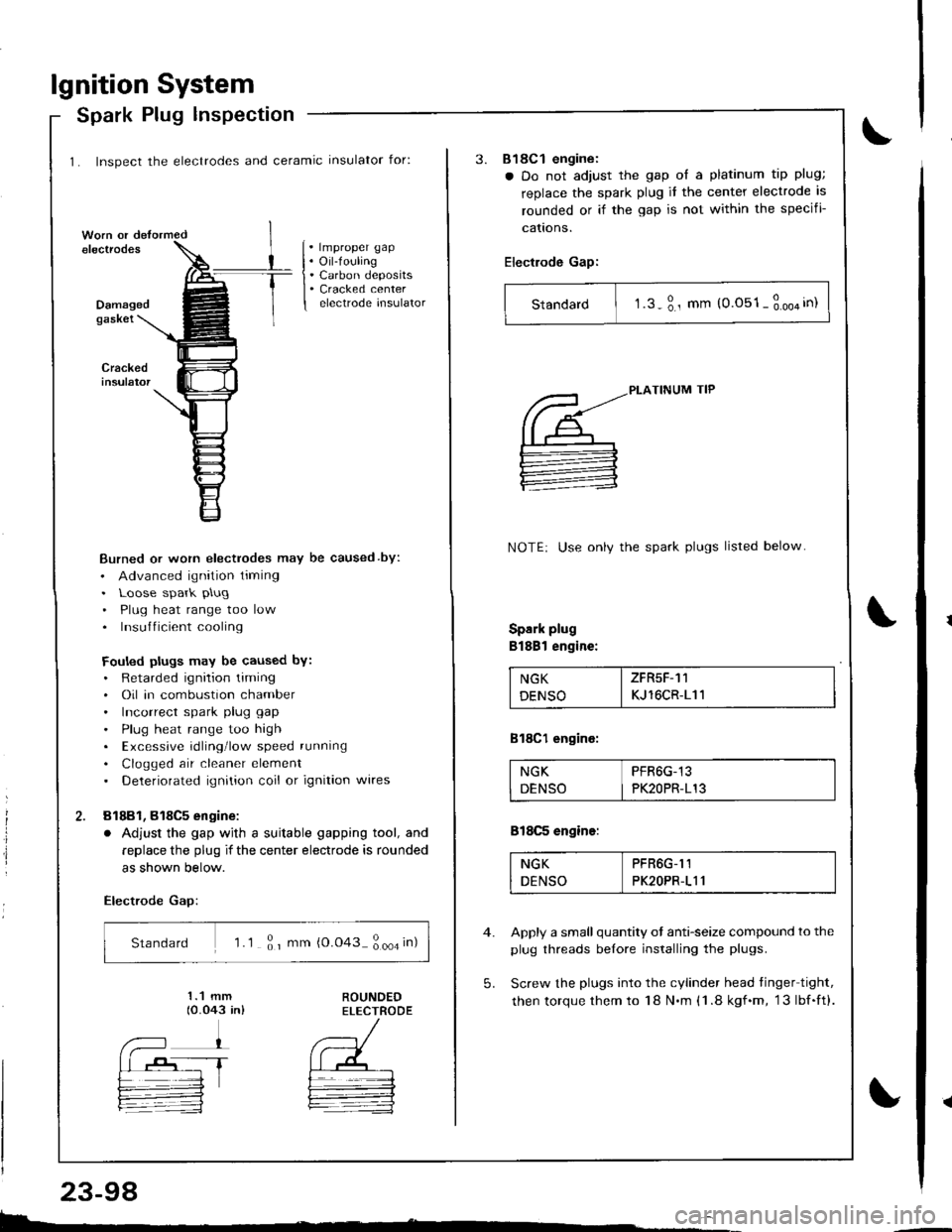
1. Inspect the electrodes and ceramic insulator for:
Spark Plug lnspection
. lmproper gap. Oil-fouling. Carbon deposits. Cracked centerelectrode insulatorDamagedgaskei
Burned or worn electrodes may be caused by:
. Advanced ignition timing. Loose spark plug
. Plug heat range too low. Insufficient cooling
Fouled plugs may be caused bY:. Retarded ignition liming. Oil in combustion chamber. Incorrect spark plug gap
. Plug heat range too high. Excessive rdling'low speed running
. Clogged air cleaner element. Deteriorated ignition coil or ignition wires
81881, 818C5 engine:
. Adjust the gap wjth a suitable gapping tool, and
replace the plug if the center electrode is rounded
as shown below.
Electrode Gap:
Standard 'l .1 ; r mm {0.043 ; ooa in)
E.
23-98
3.818C1 engine:
a Do not adjust the gap ol a platinum tip plug;
replace the spark plug it the center electrode is
rounded or if the gap is not within the specifi-
cattons.
Electrode Gap:
Standard I t.s-3., mm (0.051-3.oo4in)
5.
PLATINUM TIP
NOTE: Use onlv the spark plugs listed below
Spark plug
Bl88l engine:
NGK I ZFR5F-11
DENSO I KJ 16CR-111
818C1 engine:
NGK PFR6G-13
DENSO I PK2OPR-113
818C5 engine:
NGK PFR6G-I1
DENSO PK2OPR-111
Apply a small quantity ot anti-seize compound to the
plug threads belore installing the plugs.
Screw the plugs into the cylinder head tinger tight,
then torque them to 18 N.m (1 .8 kgf.m, 13lbf.ft).
Page 1172 of 1681
)
t
J
Altelnator ttelr Inspecuon ano Aol
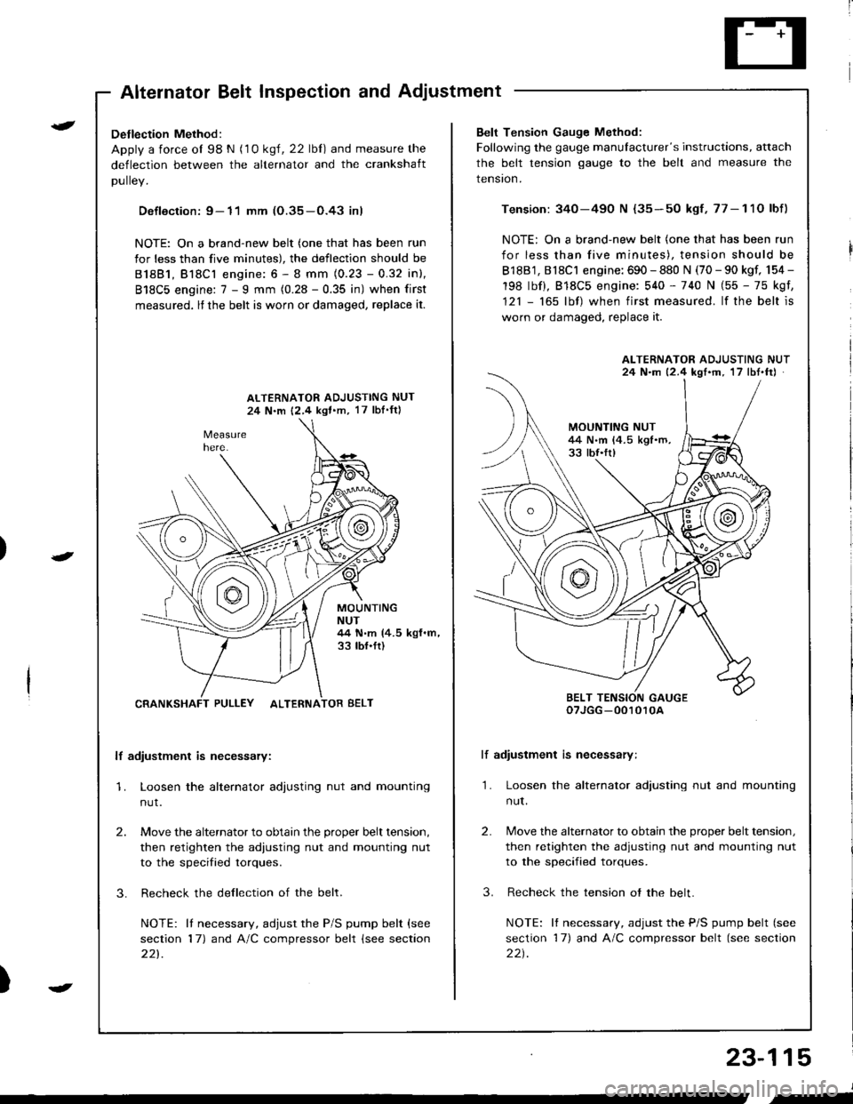
Detlection Method:
Apply a force ol 98 N (1 0 ksl, 22 lbl) and measure the
deflection between the alternator and the crankshaft
DUllev,
Defloction: 9- 11 mm (O.35-O.43 inl
NOTE: On a brand-new belt (one that has been run
for less than five minutes), the deflection should be
81881, Bl8Cl engine: 6 - 8 mm (0.23 - 0.32 inl,
818C5 engine: 7 - I mm (0.28 - 0.35 in) when first
measured, lf the belt is worn or damaged, replace it.
ALTERNATOR ADJUSTING NUT
24 N.m 12,4 kgl.m, 17 lbI'ftl
MOUNTINGNUT44 N.m (4.5 kgf.m,33 tbf.ft)
CRANKSHAFT PULLEY ALTERNATOR BELT
lf adiustment is necessary:
1. Loosen the alternator adjusting nut and mounting
nut.
2.
3.
Move the alternator to obtain the proper belt tension,
then retighten the adiusting nut and mounting nut
to the specified torques.
Recheck the dellection of the belt.
NOTE: lI necessary, adjust the P/S pump belt (see
section 17) and A/C compressor belt (see section
221.
Belt Tension Gauge Method:
Following the gauge manulacturer's instructions, attach
the belt tension gauge to the belt and measure the
tension.
Tension: 340-490 N {35-50 kgf,77-11O lbf)
NOTE: On a brand-new belt (one that has been run
for less than five minutes), tension should be
818B1, 818C1 engine: 690 - 880 N (70 - 90 kgf, 154 -
198 lbf), 818C5 engine: 540 - 740 N (55 - 75 kgf,
121 - 165 lbf) when first measured. lf the belt is
worn or damaged, replace it.
lf adiustment is necessary:
1. Loosen the alternator adjusting nut and mounting
nut.
2.
3.
Move the alternator to obtain the proper belt tension,
then retighten the adjusting nut and mounting nut
to the specified torques.
Recheck the tension ot the belt.
NOTE: It necessary, adjust the P/S pump belt (see
section 17) and A/C compressor belt (see section
22t.
ALTERNATOR ADJUSTING NUT24 N.m 12.4 kgf'm, 17 lbt.ftJ
BELT TENSION GAUGEoTJGG -0010r0A
23-115
J
,-
Page 1642 of 1681
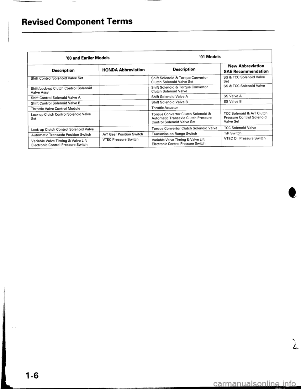
Revised Component Terms
'00 and Earlier Models'01 Models
DescriptionHONDA AbbreviationDescriptionNew Abbreviation
SAE Recommendation
Shift Control Solenoid Valve SetShift Solenoid & Torque ConvertorClutch Solenoid Valve SetSS & TCC Solenoid ValveSet
Shift/Lock-up Clutch Control SolenoidValve Assy
Shift Solenoid & Torque ConvertorClutch Solenoid Valve
SS & TCC Solenoid Valve
Shift Control Solenoid Valve AShift Solenoid Valve ASS Valve A
Shift Control Solenoid Valve BShift Solenoid Valve BSS Valve B
Throttle Valve Control ModuleThroftle Actuator
Lock-uo Clutch Control Solenoid ValveSetToroue Convertor Clutch Solenoid &Automatic Transaxle Cl utch PressureControl Solenoid Valve Set
TCC Solenoid & Av/T ClutchPressure Control SolenoidValve Set
Lock-uo Clutch Control Solenoid ValveTorque Convertor Clutch Solenoid ValveTCC Solenoid Valve
Automatic Transaxle Position SwitchA,/T Gear Position SwitchTransmission Range SwitchT/R Switch
Variable Valve Timing & Valve LiftElectronic Control Pressure Switch
VTEC Pressure SwitchVariable Valve Timing & Valve LiftElectronic Control Pressu re Switch
VTEC Oil Pressure Switch
Page 1652 of 1681
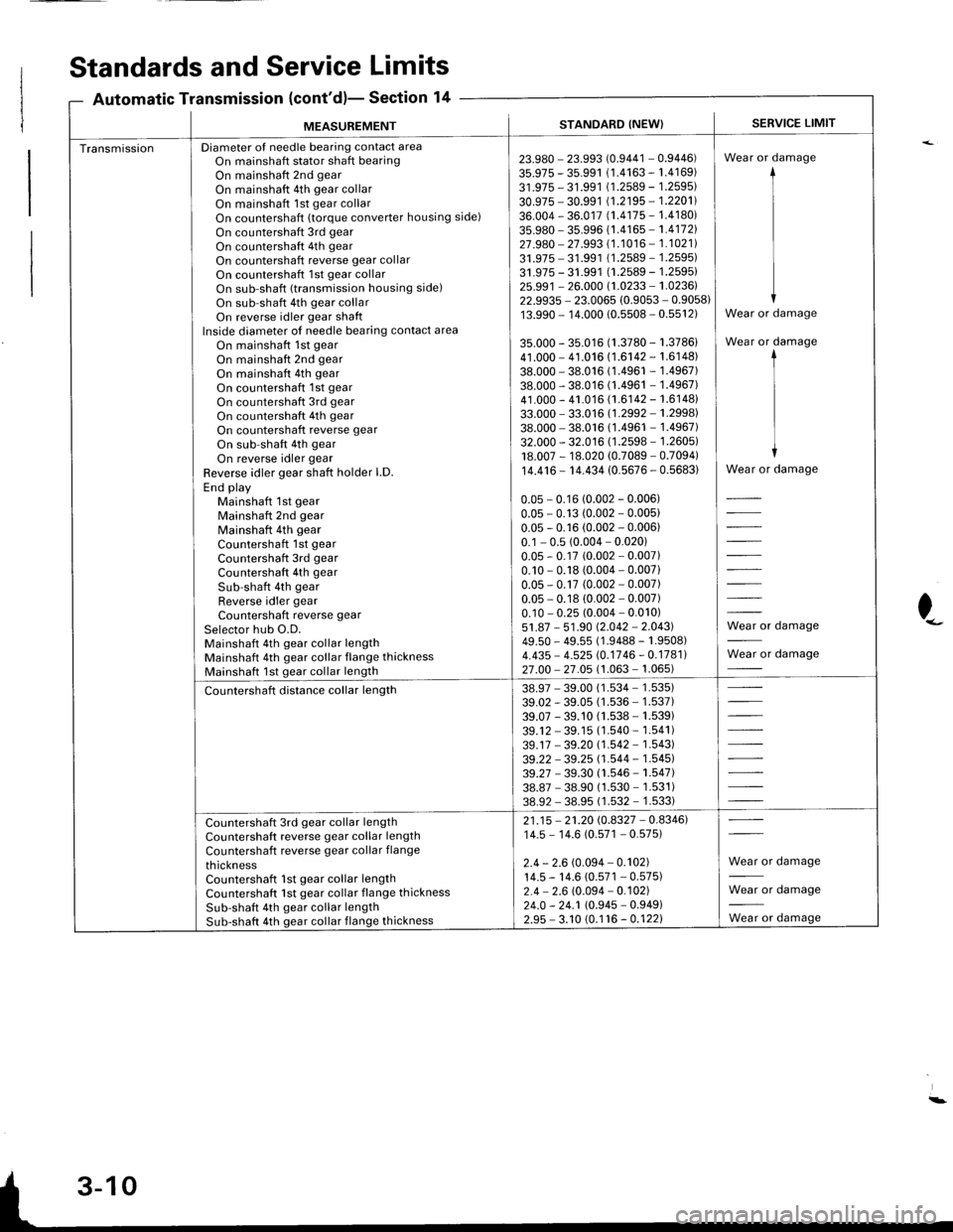
MEASUREMENTSTANDARD (NEW}SERVICE LIMIT
TransmissionDiameter of needle bearing contact areaOn mainshaft stator shaft bearingOn mainshaft 2nd gear
On mainshaft 4th gear collarOn mainshaft 1st gear collarOn countershaft (torque converter housing side)
On countershaft 3rd gear
On countershaft 4th gear
On countershaft reverse gear collarOn countershaft 1st gear collarOn sub-shaft (transmission housing side)
On sub-shaft 4th gear collarOn reverse idler gear shaftInside diameter of needle bearing contact area
On mainshaft 1st gearOn mainshaft 2nd gear
On mainshaft 4th gear
On countershaft 1st gear
On countershaft 3rd gear
On countershaft 4th gear
On countershaft reverse gear
On sub-shaft 4th gear
On reverse idler gear
Reverse idler gear shaft holder LD.End playMainshaft 1st gearMainshaft 2nd gear
Mainshaft 4th gear
Countershaft 1st gear
Countershaft 3rd gear
Countershaft 4th gear
Sub-shaft 4th gear
Reverse idler gearCountershaft reverse gear
Selector hub O.D.Mainshaft 4th gear collar lengthMainshaft 4th gear collar flange thicknessMainshaft 1st gear collar length
23.980 - 23.993 (0.9441 - 0.9446)35.975 - 35.991 (1.4163 - 1.4169)31.975 - 31.991 (1.2589 - 1.2595)
30.975 - 30.991 (1.2195 - 1.2201)
36.004 - 36.017 (1.4175 - 1.4180)
35.980 - 35.996 {1 .4165 - 1.41721
27.980 - 27.993 (1.1016 - 1.1021)31.975 - 31.991 {1.2589 - 1.2595)31.975 - 31.991 (1.2589 - 1.2595)25.991 - 26.000 (1.0233 - 1.0236)22.9935 - 23.0065 (0.9053 - 0.9058)13.990 - 14.000 (0.5s08 - 0.5512)
35.000 - 35.016 (1.3780 - 1.3786)41.000 - 41.016 (1.6142 - 1.6148)38.000 - 38.016 (1.4961 - 1.4967)38.000 - 38.016 (1.4961 - 1.4967)41.000 - 41.016 (1.6142 - 1.6148)33.000 - 33.016 (1.2992 - 1.2998)
38.000 - 38.016 (1.4961 - 1.4967)32.000 - 32.016 (1.2598 - 1.2605)18.007 - 18.020 (0.7089 - 0.7094)
14.416 - 14.434 (0.5676 - 0.5683)
0.05 - 0.16 (0.002 - 0.006)0.05 - 0.13 (0.002 - 0.005)0.05 - 0.16 (0.002 - 0.006)0.1 - 0.5 (0.004 - 0.020)0.05 - 0.17 (0.002 - 0.007)0.10 - 0.18 (0.004 - 0.007)0.05 - 0.17 (0.002 - 0.007)0.05 - 0.18 (0.002 - 0.007)0.10 - 0.25 (0.004 - 0.010)51.87 - 51.90 12.042 - 2.043149.50 - 49.55 (1 .9488 - 1 .9508)4.435 - 4.525 (0.1746 - 0.1781)27 .00 - 27 .05 (1 .063 - 1.065)
Wear or damage
Wear or damage
Wear or damage
1I
II
I
Wear or damage
Wear or damage
Wear or damage
Countershaft distance collar length38.97 - 39.00 (1 .534 - 1 .535)39.02 - 39.05 (1.536 - 1.537)39.07 - 39.10 (1.538 - 1.539)
39.12 - 39.15 (1.540 - 1.541)
39.17 - 39.20 (1.542 - 1.543)
39.22 -39.25 (1.544 - 1.545)39.27 - 39.30 (1.546 - 1.547)
38.87 - 38.90 (1.530 - 1.531)38.92 - 38.95 (1 .532 - 1 .533)
Countershaft 3rd gear collar lengthCountershaft reverse gear collar length
Countershaft reverse gear collar flange
thicknessCountershaft 1st gear collar lengthCountershaft 1st gear collar flange thicknessSub-shaft 4th gear collar lengthSub-shaft 4th gear collar flange thickness
21 .15 - 21.20 (0.8327 - 0.8346)14.5 - 14.6 (0.571 - 0.575)
2.4 - 2.6 (0.094 - 0.102)14.5 - 14.6 (0.571 - 0.575)2.4 - 2.6 (0.094 - 0.102)24.0 - 24.1 (0.945 - 0.949)2.9s - 3.10 (0.1 16 - 0.122)
Wear or damage
Wear or damage
**, damage
Standards and Service
Automatic Transmission (cont'd)-
Limits
Section 14
)--
:-
Page 1653 of 1681
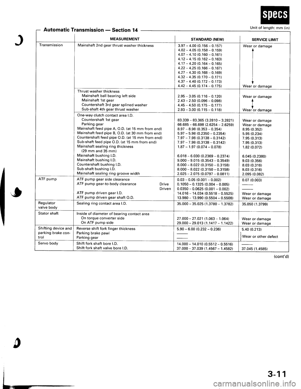
Automatic TransmissionSection 14Unit of length: mm (in)
J
o
c
MEASUREMENTSTANDARD (NEW}SERVICE LIMIT
TransmissionMainshaft 2nd gear thrust washer thickness3.97 - 4.00 (0.1 56 - 0.1 57)4.O2 - 4.05 (0.158 - 0. 1 59)4.07 - 4.10 (0.160 - 0.161 )4.12 - 4.15 (0. 1 62 - 0.163)4.17 - 4.20 (0. 164 - 0. 1 65)4.22 - 4.25 (0.166 - 0.167)4.27 - 4.30 (0.168 - 0. 169)4.32 - 4.35 (0. 170 - 0.171 )4.37 - 4.40 rc.172 - 0.17314.42 - 4.45 (0.174 - 0. 175)
Wear or damage
I
I
IWear or damage
Th rust washer thicknessMainshaft ball bearing left sideMainshaft 1st gearCountershaft 3rd gear splined washerSub-shaft 4th gear thrust washer
2.95 - 3.05 (0.116 - 0.120)2.43 - 2.50 (0.096 - 0.098)4.45 - 4.50 (0.175 - 0.17712.93 - 3.00 (0.1 15 - 0.1 18)
Wear or damage
*""1, damase
One-way clutch contact area l.D.Countershaft lst gearParking gearMainshaft feed pipe A, O.D. (at 15 mm from end)Mainshaft feed pipe B, O.D. (at 30 mm from end)Countershaft feed pipe O.D. (at 15 mm from end)Sub-shaft feed pipe O.D. (at 15 mm from end)Mainshaft sealing ring thickness(29 mm and 35 mm)Mainshaft bushing l.D.Mainshaft bushing LD.Countershaft bushing LD.Sub-shaft bushing l.D.Mainshaft sealing ring groove width
83.339 - 83.365 8.2810 - 3.2821166.685 - 66.698 (2.6254 - 2.6259)8.97 - 8.98 (0.353 - 0.35415.97 - 5.98 (0.2350 - 0.2354)7.97 - 7.98 (0.3138 - 0.3142)7.97 - 7.98 (0.3138 - 0.3142)1.87 - 1.97 (0.074 - 0.078)
6.018 - 6.030 (0.2369 - 0.237 4l9.000 - 9.015 (0.3543 - 0.3549)8.000 - 8.022 (0.3150 - 0.3158)8.000 - 8.022 (0.3150 - 0.3158)2.025 - 2.075 (0.0797 - 0.081 1)
Wear or damageWear or damage8.95 (0.352)
5.95 (0.234)7.95 (0.313)7.95 (0.313)
1.82 (0.0721
6.045 (0.2380)
9.03 (0.356)
8.03 (0.316)8.03 (0.316)
2.095 (0.082)
ATF pumpATF pump gear side clearanceATF pump gear-to-body clearance DriveDrivenATF pump driven gear l.D.ATF pump driven gear shaft O.D.
0.03 - 0.05 (0.001 - 0.00210.1 050 - 0. 1 325 (0.004 - 0.005)0.0350 - 0.0625 (0.001 - 0.002)14.016 - 14.034 (0.5518 - 0.5525)13.980 - 13.990 (0.5504 - 0.5508)
0.07 (0.003)
Wear or damageWear or damageRegulatorvalve bodySealing ring contact area l.D.35.000 - 35.025 (1 .3780 - 1 .3782135.050 (1 .3799)
Stator shaftInside of diameter of bearing contact areaOn torque converter sideOn ATF pump side27 .000 - 27 .021 (1.063 - 1.064)29.000 - 29.013 (1.1417 - 1,1 4221Wear or damageWear or damageShifting device andparking brake con-trol
Reverse shift fork finger thicknessParking brake pawlParking gear
5.90 - 6.00 (0.232 - 0.23615.40 (0.213)
f w"r, o, other defect
Servo bodyShift fork shaft bore LD.Shift fork shaft valve bore l.D.14.000 - 14.010 (0.s512 - 0.5516)37.000 - 37.039 (1.4567 - 1.4582)37.045 (1.4585)
(cont'd)
3-11
Page 1654 of 1681
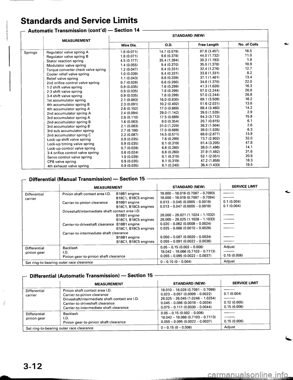
MFASIIREMENTSTANDARD (NEW}
Wire Dia.o.D.Free LengthNo. of Goils
SpringsRegulator valve spring ARegulator valve spring BStator reaction sPringModulator valve springTorque converter check valve springCooler relief valve springRelief valve spring2nd orifice control valve spring1-2 shift valve spring2-3 shift valve spring3-4 shift valve spring1st accumulator spring4th accumulator spring B4th accumulator spring A2nd accumulator spring A3rd accumulator spring A2nd accumulator spring B3rd accumulator spring B3rd sub accumulator spring2nd accumulator spring CLock-up shift valve springLock-up timing valve springLock-up control valve spring3-4 orifice control valve springServo control valve springCPB valve spring4th exhaust valve spring
1.8 (0.071)
1.8 (0.071)
4.5 rc.177].1.4 (0.05s)
1.2 10.047l.1.0 (0.039)
1.1 (0.043)
0.7 (0.0281
0.9 (0.035)
0.9 (0.035)
0.9 (0.035)
2.1 (0.083)
2.3 (0.091)
2.6 (0.102)
2.4 (0.094)
2.8 (0.110)
1.6 (0.063)
2.1 (0.083)
2.7 (0.106)
2.2 l0.o87l0.9 (0.035)
0.9 (0.035)
0.7 (0.028)
0.6 (0.024)
1.0 (0.039)
0.9 (0.0351
0.9 (0.035)
14.7 (0.5791
9.6 (0.378)
35.4 (1 .394)9.4 (0.370)
8.4 (0.331)
8.4 (0.331)
8.6 (0.339)
6.6 (0.260)
7.6 (0.299)
7.6 (0.299)
7.6 (0.299)
16.0 (0.630)
10.2 rc.402117.0 (0.669)
29.0 11.142117.5 (0.689)
9.0 (0.354)
31.0 (1 .220)17.0 (0.669)
14.5 (0.571)
7.6 (0.299)
8.1 (0.319)
6.6 (0.260)
6.6 (0.260)
8.1 (0.319)
8.1 (0.319)
6.1 (0.240)
87.8 (3.457)
44.0 (1.732\
30.3 (1.193)
35.0 (1.378)
32.4 (1.2761.
33.8 (1.331)
37.1 (1.461)
34.8 (1.370)
41.3 (1.626)
57.0 12.244157.0 12.244].89.1 (3.508)
s1.6 (2.0311
88.4 (3.480)
39.0 (1 .53s)94.3 (3.713)
20.7 (0.815)
38.2 (1.504)
39.0 (1.535)
68.0 (2.677)
73.7 (2.9021
81.4 (3.205)
38.0 (1.496)
37.9 (1.492)
52.1 (2.0511
47.2 (1 .858)36.4 (1.433)
16.51 1.01.910.912.78.213.422.01A ?
26.826.8't6.2
13.814.2z.J15.9o. l2.66.313.932.O47.814.1?1 A
20.8ttJ.JI v.5
Standards and Service Limits
Automatic Transmission (cont'd) - Section 14
Differential (Manual Transmission) - Section 15
Differential (Automatic Transmission) - Section 15
ilt5stlrrr, - 4,
MEASUREMENTSTANDARD (NEW}SERVICE LIMIT
Differentialca rnerPinion shaft contact area l.D. 81881 engineB18C1, 818C5 engines
Carrier-to-pinionclearance Bl88lengine818C1, 818C5 enginesDriveshafVintermediate shaft contact area l.D.81881 engine818C1. 818C5 engines
Carrier-to-driveshaft clearance 81881 engine818C1, 818C5 engines
Carrier-to-intermediate shaft clea rance81881 engine818C1, 818C5 engines
18.000 - 18.016 (0.7087 - 0.7093)18.000 - 18.018 (0.7087 - 0.7094)0.013 - 0.045 (0.0005 - 0.0018)0.013 - 0.047 (0.0005 - 0.0019)
28.000 - 28.021 11.1024 - 1.1032].28.005 - 28.025 l1 .'�t026 - 1 .1 033)
0.020 - 0.062 (0.0008 - 0.0024)0.025 - 0.066 (0.0010 - 0.00261
0.050 - 0.087 (0.0020 - 0.0034)0.055 - 0.091 (0.0022 - 0.0036)
- toooot0.1 (0.004)
Differentialpinion gearBacklasht.D.Pinion gear-to-pinion shaft clearance
0.05 - 0.15 (0.002 - 0.006)18.042 - 18.066 (0.7103 - 0.71 1 3)0.055 - 0.095 (0.0022 - 0.0037)
Adjust
0.15 (0.006)
Set ring-to-bearing)uter race clearance0 - 0.10 (0 - 0.004)Adjust
nsmlssaonl - Sectton
MEASUREMENTSERVICE LIMITSTANDARD (NEW}
Differentialca rrierPinion shaft contact area l.D.Carrier-to-pinion clearanceDriveshaft/i ntermediate shaft contact are l.D.
Carrier-to-driveshaft clearanceCarrier-to-intermediate shaft clearance
18.010 - 18.028 (0.7091 - 0.7098)0.023 - 0.057 (0.0009 - 0.0022)26.025 - 26.045 11.0246 - 1.02541
0.045 - 0.086 (0.0018 - 0.0034)0.075 - 0.1 11 (0.0030 - 0.0044)
0.1 (0.004)
0.12 (0.005)
0.15 (0.006)
Differentialpinion gearBacklasht.D.Pinion gear-to-pinion shaft clearance
0.05 - 0.15 (0.002 - 0.006)18.042 - 18.066 (0.7 103 - 0.71 1 3)0.055 - 0.095 (0.0022 - 0.0037)0.15 (0.006)
Set ring-to-bearing outer race clearance0 - 0.15 (0 - 0.006)Adiust
uL-
3-12
(-
Page 1657 of 1681
{b
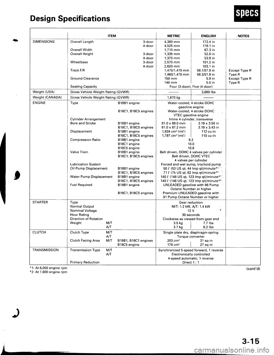
Design Specifications
x1: At 6,000 engine rpm*2: At 7,600 engine rpm
0
(cont'd)
{
ITEMMETRICENGLISHNOTES
DIMENSIONSOverall Length 3-door4-doorOverall WidthOverall Height 3-door4-doorWheelbase 3-door4-doorTrack F/R
Ground Clearance
Seating Capacity
4,380 mm4,525 mm1,710 mm1,335 mm ]1,370 mm ]2,57O mm2,62O mm 11 ,415/1,470 mm I1,480/1,470 mm I1s0 mm I140 mm IFour (3-door),
172.4 in178.1 in67.3 in52.6 in53.9 in101.2 in103.1 in58.1/57.9 in58.3/57.9 in5.9 in5.5 tnFive (4-door)
Except Type RType RExcept Type RType R
weisht (usA)Gross Vehicle Weight Rating (GVWR)3.680 rbs
Weight (CANADA)Gross Vehicle Weight Rating (GVWR)1,670 kg
ENGINEType
Cylinder ArrangementBore and Stroke
Displacement
Compression Ratio
Valve Train
Lubrication SystemOil Pump Displacement
Water Pump Displacemenl
Fuel Required
8188l engine
818C1, Bl8C5 engines
81881 engine818C1, 818C5 engines81881 engine818C1, B18C5 engines81881 engine818C1 engine818C5 engineB1881 engine818C1, B18C5 engines
81881 engine818C1, B18CS enginesB1881 engine818C1, 818C5 enginesB1881 engine
818C1,818C5 engines
Water-cooled. 4-stroke DOHCgasoline engineWater-cooled, 4-stroke DOHCVTEC gasoline engineInline 4-cylinder, transverse81.0 x 89.0 mm | 3.19 x 3.50 in81.0 x 87.2 mm | 3.19 x 3.43 in1,834 cm3 (m/ ) | 112 cu-in1,797 cm3 (m/ ) | 110 cu-in9.210.010.6Belt driven, DOHC 4 valves per cylinderBelt driven, DOHC VTEC4 valves per cylinderForced and wet sump, trochoid pump50 f (53 US qt, 44 lmp qt)/minute*'71 ( (75 US qt,62 lmp qt)/minute*'� :
140 I 1148 US qt. 123 lmp qtl/minute*1140 t (148 US qt, 123 lmp qt)/minute*2UNLEADED gasoline with 86 PumpOctane Number or higherPremium UNLEADED gasoline with91 Pump Octane Number or higher
STARTERTypeNormal OutputNominal VoltageHour RatingDirection of RotationWeight MffAIT
Gear reductionMfi:1.2 kW, A,/T: 1.4 kW12V ,
30 secondsClockwise as viewed from gear end3.5 ks | 7.7 lbs3.7 kg | 8.2 lbs
CLUTCHClutch Type
Clutch Facing Area
M/TAfiM/T 81881, 818C1 engines818C5 engine
Single plate dry, diaphragm springTorque converter203 cm2 , 31 sq-in176 cm2 | 27 sq-in
TRANSMISSIONTransmission Type
Primary Reduction
M/TAITSynchronized S-speed forward, 1 reverseElectronical ly control led4-speed automatic, 1 reverseDirect 1 : 1
3-15