torque HONDA INTEGRA 1998 4.G Repair Manual
[x] Cancel search | Manufacturer: HONDA, Model Year: 1998, Model line: INTEGRA, Model: HONDA INTEGRA 1998 4.GPages: 1681, PDF Size: 54.22 MB
Page 622 of 1681
J
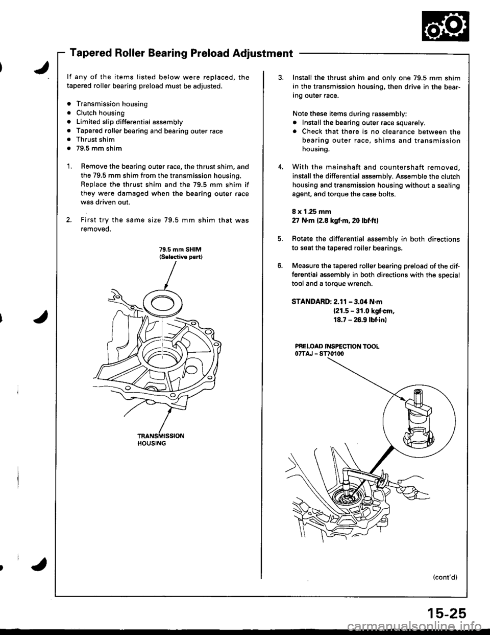
Tapered Roller Bearing Preload Adjustment
lf any of the items listed below were replaced, the
tapered roller bearing preload must be adjusted,
. Transmission housing
. Clutch housing
. Limited slip diffsrential assembly
. Tapored roller bearing and bearing outer race. Thrust shim
. 79,5 mm shim
Remove the bearing outer race, the thrust shim, and
the 79,5 mm shim from the transmission housing.
Replace the thrust shim and the 79.5 mm shim if
they were dsmaged when the bearing outer race
was driven out.
First try the same size 79.5 mm shim that was
removeo.
HOUSING
Install the thrust shim and only one 79.5 mm shim
in the transmission housing, then drive in the bear-
Ing our€r race.
Noto these items during rassembly:
. Install the bearing outer race squarely.. Check that there is no clearance between the
bearing outer race, shims and transmission
housing,
With the mainshatt and countershaft removed,
installthe differential assemblv. Assemble the clutch
housing and transmission housing without a sealing
a9ent, and torque the case bolts.
8 x 1.25 mm
27 N.m (2.8 kgf.m, 20 lM.ft)
Rotate the differential assemblv in both directions
to seat the tapered roller bearings.
Measur€ the tapered roller bearing preload of the dif-
ferential assembly in both directions with the special
tool and a toroue wrench.
STANDARD: 2.11 - 3.04 N.m(2!.5 - 31.0 kgt'cm,
18.7 - 26.9 lbf.in)
PNELOAD INSPECTION TOOL07TAJ - ST701dt
(cont'd)
15-25
Page 628 of 1681
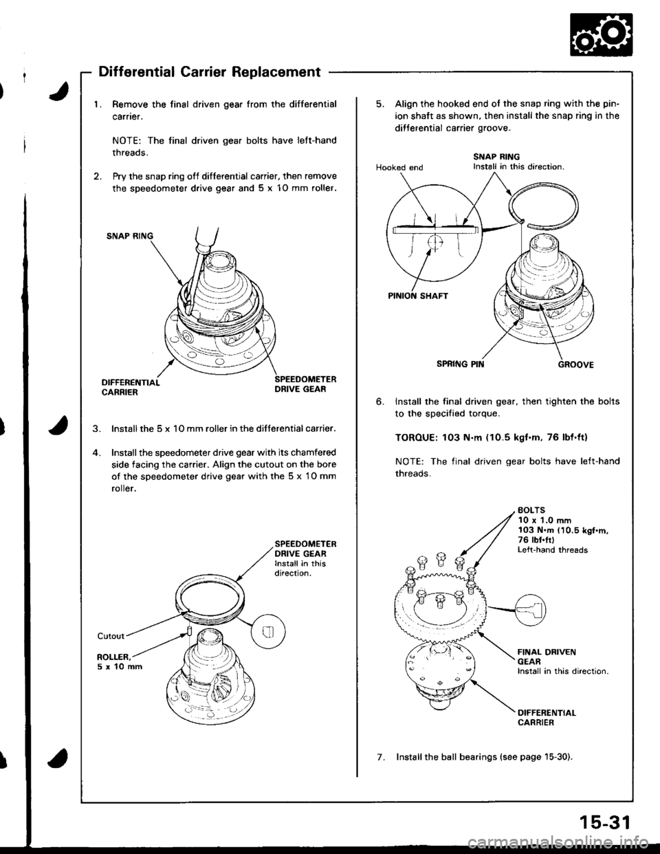
J1. Remove the final driven gear from the differential
carner.
NOTE: The final driven gear bolts have left-hand
threads.
2. Pry the snap ring ofl differential carrier, then remove
the speedometer d.ive gear and 5 x 1O mm roller.
SNAP RING
DIFFERENTIALCARRIERDRIVE GEAR
lnstall the 5 x 1O mm roller in the differential carrier.
Installthe speedometer drive gear with its chamfered
side facing the carrier. Align the cutout on the bore
of the speedometer drive gear with the 5 x 1O mm
ro er.
SPEEDOMETERDRIVE GEARInstall in thisdirection.
Cutout
ROLLER,5x10mm
5. Align the hooked end ot the snap ring with the pin-
ion shaft as shown. then install the snap ring in the
dilJerential carrier groove.
Hooked endSNAP RINGInstall in this direction.
6.Install the final driven gear, then tighten the bolts
to the specified torque.
TOROUE: 103 N.m (10.5 kgt.m, 76 lbl.ttl
NOTE: The final driven gear bolts have left-hand
threads.
BOLTS10 x 1.0 mm103 N.m (10.5 kgf.m,76 rbt.frlLeft-hand threads
FINAL DRIVENGEARInstall in this direction.
DIFFERENTIALCARRIER
7. Installthe ball bearings (see page 15-30).
Page 629 of 1681
Differential (Automatic Transmissionl
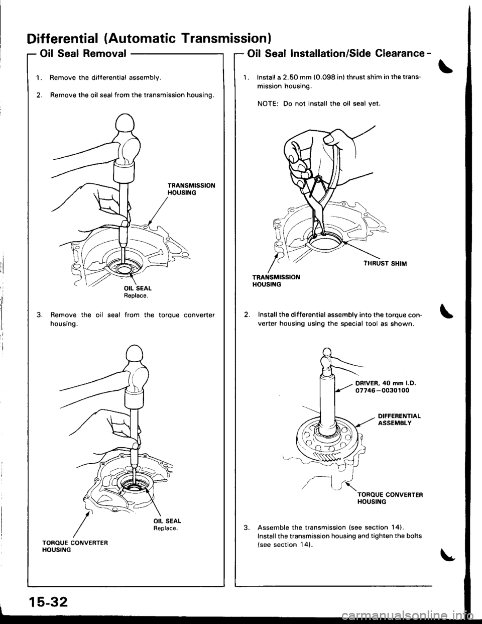
Oil Seal Removal
Remove the differential assembly.
Remove the oil sealfrom the transmission housing.
Remove the oil seal from the torque converter
housing.
Oil Seal Installation/Side Clearance-
1 . Install a 2.50 mm {O.O98 in} thrust shim in the trans-
mission housing.
NOTE: Do not install the oil seal yet.
TRANSMISSIONHOUStf{G
Install the differential assembly into the torque con-
verter housing using the special tool as shown.
DRIVER, 40 mm l.D.07746-0030100
DIFFERENTIALASSEMBLY
/--1TOROUE CONVERTERHOUSING
Assemble the transmission lsee section 141.
Installthe transmission housing and tighten the bolts(see section 14).TOROUE CONVERTERHOUSING
15-32
OIL SEALReplace.
Page 630 of 1681
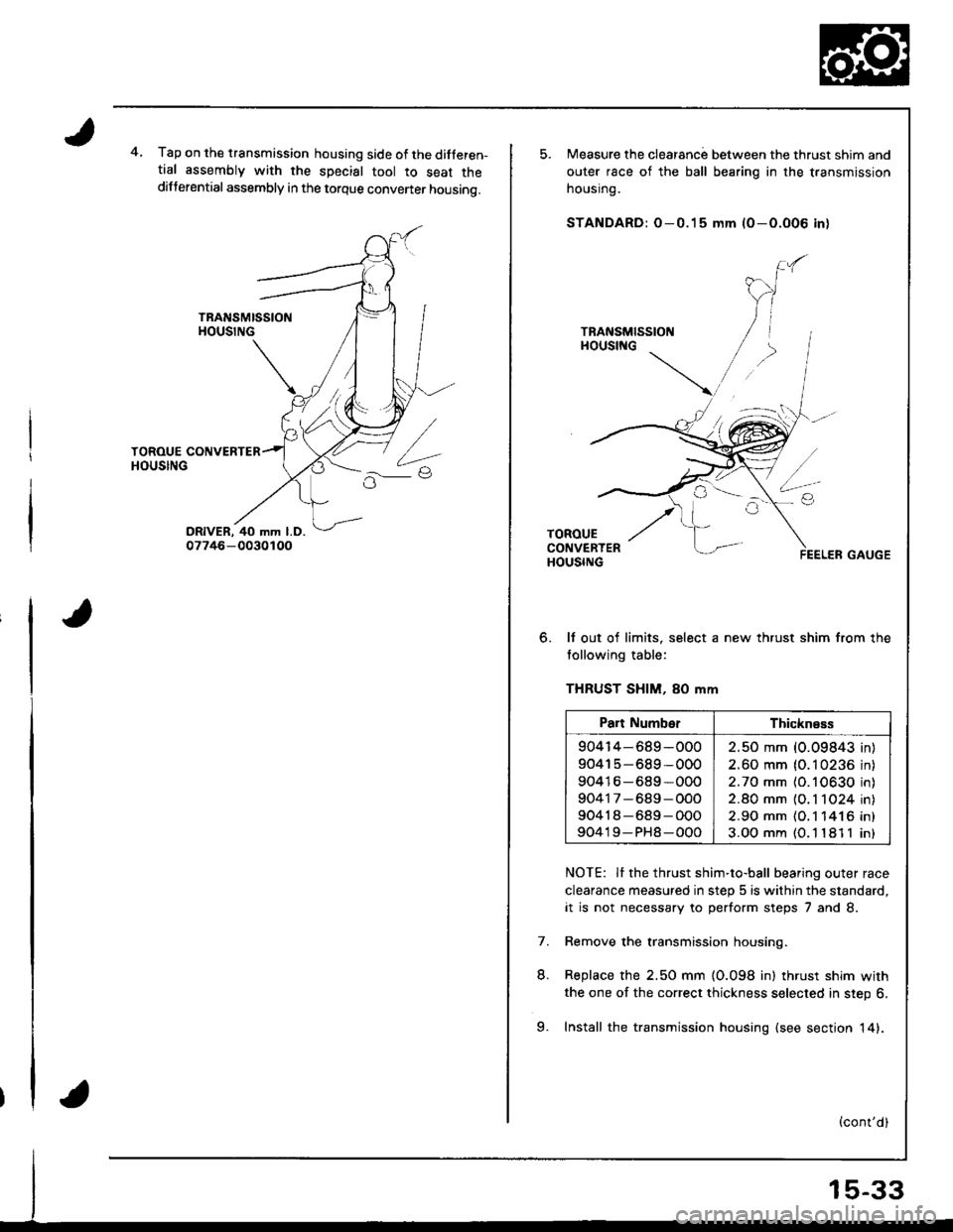
4.Tap on the transmission housing side of the ditferen-tial assembly with the special tool to seat thedifferential assembly in the torque convener housing.
o.
Measure the clearanc; between the thrust shim and
outer race of the ball bearing in the transmission
nousrng.
STANDARD: O-0.15 mm (O-O.O06 in)
It out of limits. select a new thrust shim from the
tollowing table:
THRUST SHIM, 80 mm
NOTE: Il the thrust shim-to-ball bearing outer race
clearance measured in step 5 is within the standard,
it is not necessary to perform steps 7 and 8.
Remove the transmission housing.
Replace the 2.50 mm {0.098 in) thrust shim with
the one of the correct thickness selected in step 6.
Install the transmission housing (see sectjon 14).
7.
L
Part NumberThickness
904r4-689-000
90415-689-000
90416-689*000
90417-689-OOO
90418-689-O00
90419-PH8-000
2.50 mm (0.09843 in
2.60 mm (0.10236 in
2.70 mm (O.10630 in
2.80 mm {O. 1 1O24 in
2.90 mm {O.1 141 6 in
3.OO mm (O. l '181 1 in
9.
Page 631 of 1681
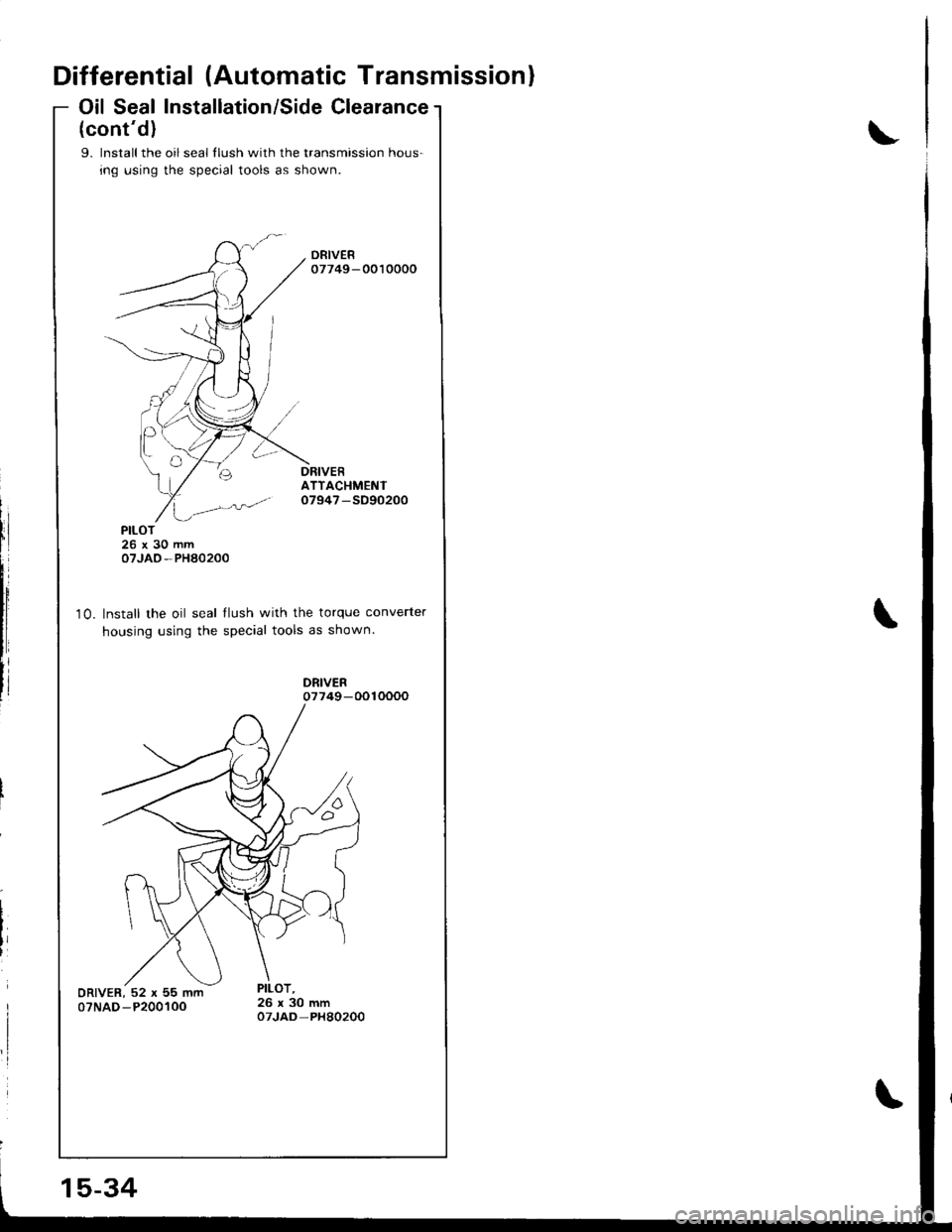
Differential (Automatic Transmission)
Oil Seal Installation/Side Clearance
(cont'd)
9. lnstall the oil seal llush with the transmission hous-
ing using the special tools as shown.
ATTACHMENTo7947 -SD90200
10.
PILOT26x30mmoTJAO-PHA0200
Install the oil seal llush with the torque converter
housing using the special tools as shown.
15-34
Page 646 of 1681
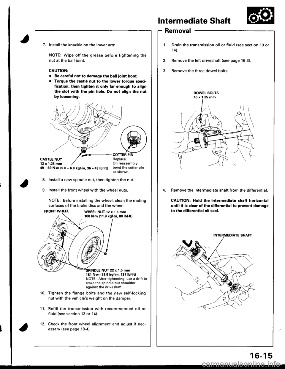
Intermediate Shaft
Removal
Drain the transmission oil or fluid {see section 13 or
14t.
Remove the left driveshaft (see page 16-3).
Bemove the three dowel bolts.
Remove the intermediate sh8ft from the differential.
CAUTION: Hold the intermediate shaft horizontal
until it is clear ot th6 difforantirl to prevont damage
to thc ditf€rential oil seal.
7. Install the knuckle on the lower arm.
NOTE: Wipe off the grease before tightening the
nut at the ball joint.
CAUTION:
. Be careful not to damago the ballioint boot.
. Torque the castle nut to tho low€r torque speci-
tication, then tighten it only lar onough to align
th6 slot whh tho pin hols. Do not align the nut
by loosening.
,.<__coTTEF PtNCASTLE NUT12 x 1.25 mm49 - 59 N.m {5.0 - 5.0 kgf.m, 36 - t3 lbl.ft)
Beplace.On reassembly,bend the cotter pin
8. Install a new spindle nut, then tighten the nut.
9. Installthe front wheel with the wheel nuts.
NOTE: Before installing the wheel, clean the mating
surfaces of the brake disc and the wheel.
FRONT WHEELWH€EL NUT 12 x 1.5 mm108 N.m (11.0 kgt m,80lbf ft)
10.
NUT 22 x '1.5 mm181 N m 118.5 kgl.m, 134lbtftlNOTE: After tightening, use a drift tostake the spindle nut shoulderagainst the driveshatt.
Tighten the flange bolts and the new self-locking
nut with the vehicle's weight on the damper.
Refill the transmission with recommended oil or
fluid (see section 13 or 14).
11.
12. Check the front wheel alignment and adjust if nec-
essary (see page 18-4).
INTERMCOIATE SHAFT
16-15
Page 660 of 1681
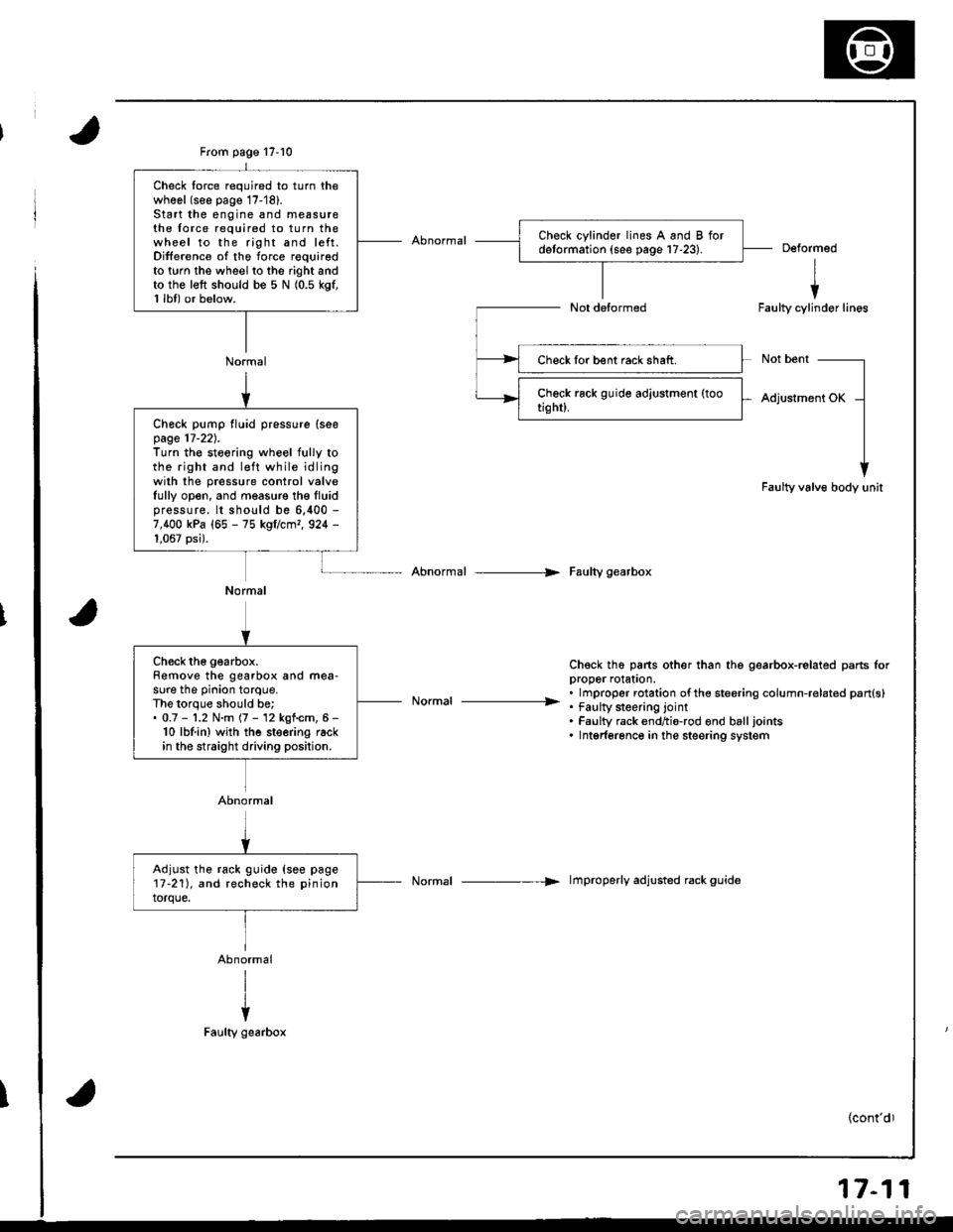
From page 17-10
Normal
Check lorce required to turn thewhool (see page 17-'18).Start the engine and measu16the force required to turn thewheel to the right and left.Difference of the force requiredto twn the wheel to the right andto the left should be 5 N (0.5 kgf,1 lbl) or below.
Deformed
I
iFaulty cylinder lines
Not bent
Adjustment OK
Faulty valve body unit
Abnormal --> Faulty gearbox
Ch€ck th6 pans other than the gearbox-related parts lorDrooer rolaton.
. . lmproper rotation ofthe steering column-related pan{s}----------------- . tau[y $eenng lornt. Faulty rack endtio-rod ond balljoints. Intgrferonce in the steering system
Normal -----> lmproperly adjusted rack guide
Check lor bent rack shaft.
Check pump fluid pressure (seepage 17-22).Turn the steoring wheel fully tothe right and l€ft while idlingwilh the pressure control valveIully open, and measure the Iluidpressure. lt should be 6,400 -
7,400 kPa (65 - 75 kgflcmr, 924 -
1,067 psi).
Normal
Ch€ck the gearbox.Remove the gearbox and mea-sure the pinion torque.The lorque should be;. 0.7 - '1.2 N.m (7 - 12 kgf.cm, 6 -
10 lbf.in) wjth the steering rackin the straight driving position.
Abnormal
Adjust the rack guide {see page17-211, and recheck the pinion
torque.
17-11
Page 661 of 1681
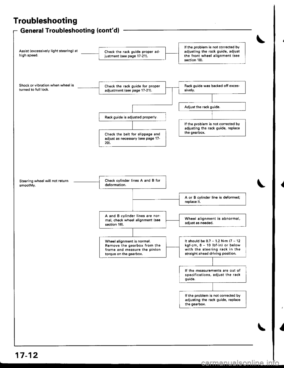
Troubleshooting
General Troubleshooting (cont'dl
Assist (excessively light steering) athigh speod.
Shock or vibration when wheel isturned to full lock.
Steering wheel will not return
smoothly.
a-, aa GrI r- tz
ll the problom is not correcled byadiusting the rack guide, adjustthe front wh66l alignment (see
s6ction 18).
Ch6ck th6 rack guide propgr ad-justment (see pago 17-21).
Check the rack guido lor proper
adjustment (see page 17-21).
Rack guid€ is adjusted properly.
lf the problem is not corrected byadjusting the rack guide, replscothe gearbox.Check the belt for slippage andadjust as nec€ssary {s6e page 17-20).
A and B cylinder lines are nor-mal, chgck wheol alignment (se€
section 18).
Whe6l alignment is abnormal,adjust as needod.
It should be 0.7 - 1.2 N.m {7 - 12kgl.cm.6 - 10 lbf.in) or belowwith the steering rack in thestraight ahoad driving position.
wh€el alignment is normal.R€mov€ the gearbox from thofram6 snd measure the pinion
torque on the gearbox.
lf the measurements are out ofsp€cifications. adjust the rackgurd9.
It the problom is not corrected byadiusting the rack guido. r€placethe goarbox.
{
I
Page 681 of 1681
Steering Column
Installation (cont'dl
CAUTION:
a All SRS wire harness€s are covored with yollow insu-
lation. B€fors you disconnect any part of an SRS wire
harness. disconnoct the airbag connoctois.
a Whenever the ignition switch is ON (lll, or has beon
turned OFF for less than throo minutos, be caleful not
to bump the SRS unit; ths airbags could accidsntslly
deploy and caus€ damago or iniuries.
a For additionalpracautions, reter to the SRS sub-section
in section 23,
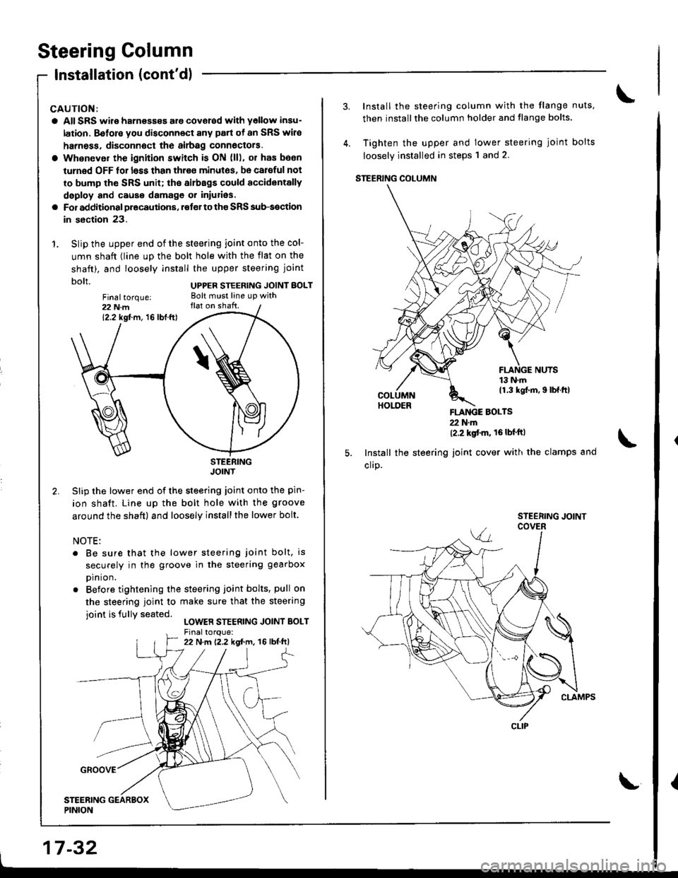
1. Slip the upper end of the steering joint onto the col-
umn shaft (line up the bolt hole with the flat on the
shaft). and loosely install the upper steering joint
bolt UPPER STEERTNG JorNT BoLT
STEERINGJOINT
Slip the lower end of the steering joint onto the pin-
ion shaft. Line up the bolt hole with the groove
around the shaft) and loosely installthe lower bolt.
NOTE:
. Be sure that the lower steering joint bolt, is
securely in the groove in the steering g€arbox
prn ron.
. Before tightening the steering joint bolts, pull on
the steering ioint to make sure that the steering
ioint is fullY seated.LOWER STEERING JOINT BOLT
Fin6ltorque:22 N.m12.2 kgf.m, 16 lbf.ft)
17-32
Install the steering column with the flange nuts,
then installthe column holder and flange bolts.
Tighten the upper and lower steering joint bolts
loosely installed in steps'l and 2.
STEERING COLUMN
FLANGE BOLTS22 N'm(2.2 kgt'm' 16lbf'ftl
Install the steering joint cover with the clamps and
cllP.
CLIP
\{
Page 704 of 1681
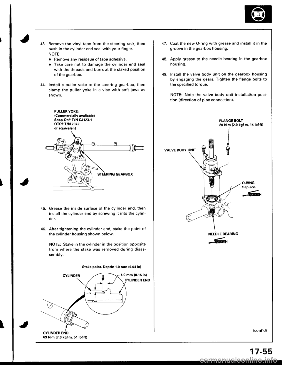
Remove the vinyl tape from the steering rack, then
push in the cylinder end seal with your finger.
NOTE:
. Remove any resideue of tape adhesive.
. Take care not to damage the cylinder end seal
with the threads and burrs at the staked position
of the gearbox.
Install a puller yoke to the steering gearbox, then
clamp the puller yoke in a vise wjth soft jaws as
shown.
PULLER YOKEI{Commcrci.lly .vailablelSn.p-On@ T/N c.r123-1oTc€ T/N 7372or equivalent
Grease the inside surface of the cylinder end. then
install the cylinder end by screwing it into the cylin
der,
After tightening the cylinder end, stake the point of
the cylinder housing shown below.
NOTE: Stake in the cylinder in the position opposite
from where the stake was removed during disas-
semory.
Stake point. Dopth: 1.0 mm (0.04 inl
4.0 mm (0.16 inl
CYLINOER END
46.
\
47.
49.
coat the new o-ring with grease and install it in the
groove in the gearbox housing.
Apply grease to the needle bearing in the gearbox
ho using.
Install the valve body unit on the gearbox housing
by engaging the gears. Tighten the flange bolts to
the specified torque.
NOTE: Note the valve body unit installation posi-
tion (direction of pipe connection).
VALVE BODY UNIT
(cont'd)
O.RINGReplace.
-611
NEEDLE AEARING
-Grl
17-55