torque HONDA INTEGRA 1998 4.G Repair Manual
[x] Cancel search | Manufacturer: HONDA, Model Year: 1998, Model line: INTEGRA, Model: HONDA INTEGRA 1998 4.GPages: 1681, PDF Size: 54.22 MB
Page 579 of 1681
![HONDA INTEGRA 1998 4.G Repair Manual 18. Install the sub-shaft assembly in the transmission
housing {see page 14-142],.
19. Install the reverse idler gear and gear shaft holder(see page 14-158).
20. Install the differential assembly in HONDA INTEGRA 1998 4.G Repair Manual 18. Install the sub-shaft assembly in the transmission
housing {see page 14-142],.
19. Install the reverse idler gear and gear shaft holder(see page 14-158).
20. Install the differential assembly in](/img/13/6069/w960_6069-578.png)
18. Install the sub-shaft assembly in the transmission
housing {see page 14-142],.
'19. Install the reverse idler gear and gear shaft holder(see page 14-158).
20. Install the differential assembly in the torque con
verter housrng.
21. Assemble the mainshaft and countershaft sub-
assembly, then install them together in the torque
converler noustng.
22. Turn the shilt fork so the large chamlered hole is fac-
ing the fork bolt hole, then installthe shift tork with
the reverse selector and torque the lock bolt. Bend
the lock tab against the bolt head.
SHIFT FORK
23. Install the reverse gear with the collar and needte
bearing on the countershaft.
24. Align the spring pin of the control shaft with the
transmission housing groove by turning the control
shaft.
25. Place the transmission housing on the torque con-
verter housing with a new gasket and the three
dowel pins.
CONTROL
TRANSMISSION HOUSING
lnstall the transmission housing mounting bolts along
with the transmission hanger and the connector
bracket, then torque the bolts in two or more steps
in the sequence shown.
TOROUE: rt4 N'm (4.5 kgt.m, 33 lbt.lt)
TRANSMISSION
26.
LOCK WASHERReplace.
6 x 1.0 mm4 t{.m(1.4 kgf.m, 10
e
Large chamfered hole
/ -'K\,,
a
14-163
Page 580 of 1681
Transmission
SUB.SHAFT
MAINSHAFT
Reassembly {cont'd)
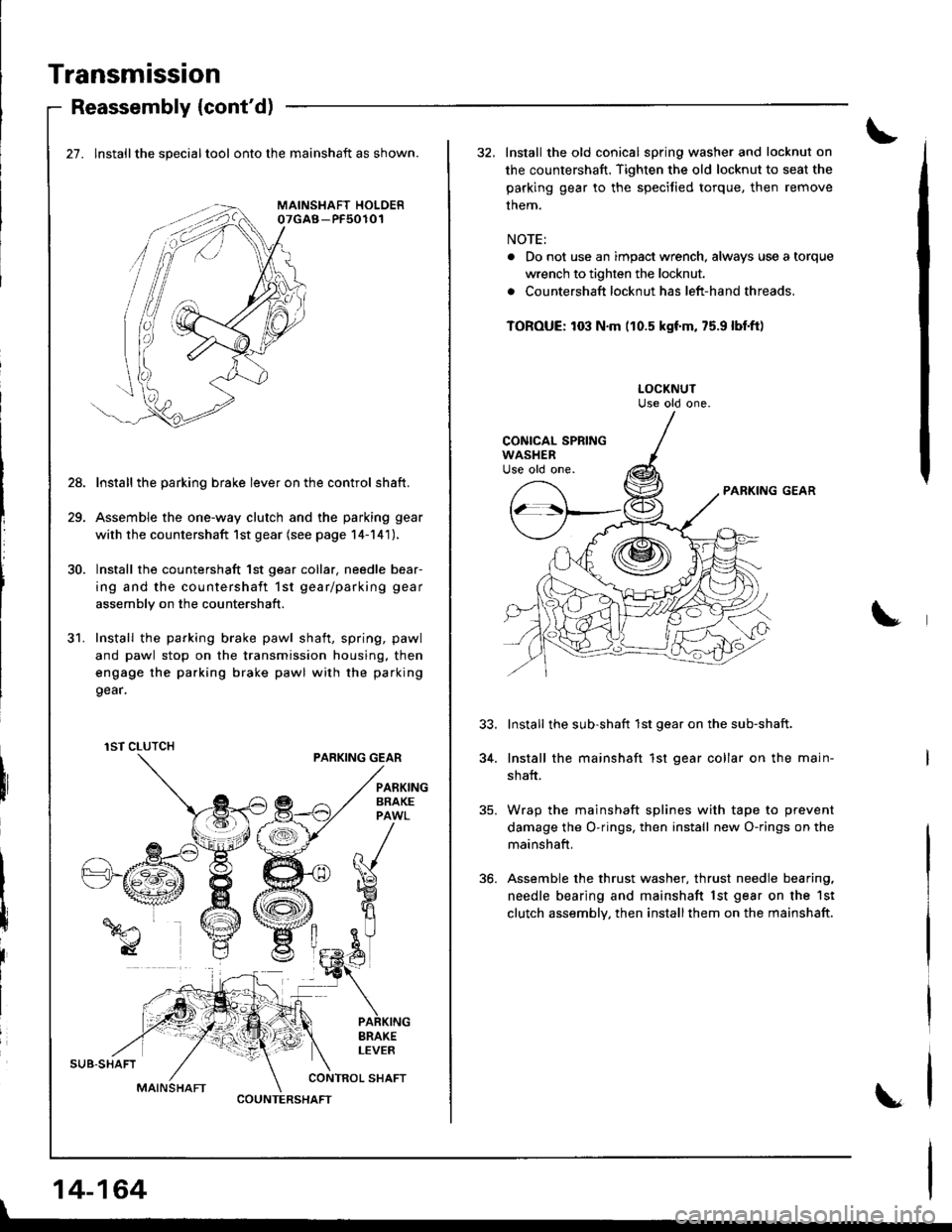
27. lnstallthe specialtool onto the mainshaft as shown.
Install the parking brake lever on the control shaft.
Assemble the one-way clutch and the parking gear
with the countershaft 1st gear (see page 14-141),
Install the countershaft 1st gear collar. needle bear-
ing and the countershaft 1st gear/parking gear
assembly on the countershaft.
Install the parking brake pawl shaft, spring, pawl
and pawl stop on the transmission housing. then
engage the parking brake pawl with the parking
9ear.
PARKING GEAR
28.
31.
I
I
iIBRAKELEVER
CONTROL SHAFT
1ST CLUTCH
COUNTERSHAFT
|
14-164
32, Install the old conical spring washer and locknut on
the countershaft. Tighten the old locknut to seat the
parking gear to the speciJied torque, then remove
them.
NOTE:
. Do not use an impact wrench, always use a torque
wrench to tighten the locknut.
. Countershaft locknut has left-hand threads,
TOROUE: to3 N.m (10.5 kgf'm, 75.9 lbl.ft)
PARKING GEAR
Install the sub-shaft 1st gear on the sub-shaft.
Install the mainshaft 1st gear collar on the main-
shaft.
Wrap the mainshaft splines with tape to prevent
damage the O-rings, then install new O-rings on the
mainshaft,
Assemble the thrust washer, thrust needle bearing,
needle bearing and mainshaft lst gear on the 1st
clutch assembly, then installthem on the mainshaft.
34.
Page 581 of 1681
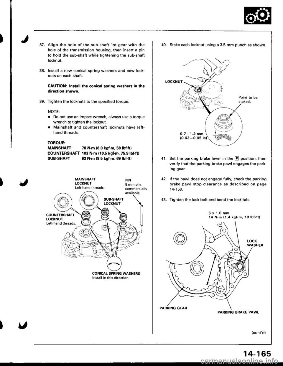
)37.
38.
Align the hole of the sub-shaft 1st gear with the
hole of the transmission housing. then insert a pin
to hold the sub-shaft while tightening the sub-shaft
locknut.
Install a new conical spring washers and new lock-
nuts on each shaft.
CAUTION: ln3tall the conical spring washers in the
direction shown.
Tighten the iocknuts to the specified torque.
NOTE:
a Do not use an impact wrench, always use a torque
wrench to tighten the locknut.
. Mainshaft and countershaft locknuts have left-
hand threads.
TOROUE:
MAINSHAFT 78 N.m {8.0 kgf.m, 58 lbf.ft}
COUNTERSHAFT 103 N.m {10.5 kgf.m, 75.9 lbtft}
SUB-SHAFT 93 N.m (9.5 ksf.m, 69 lbf.ftl
)
MAINSHAFTLOCKNUTLeft hand threads.
PIN8 mm pin,commercially
40. Stake each locknut using a 3,5 mm punch as shown.
LOCKNUT
O.7 -1.2 mm(0.03 -O.05 inl
Set the parking brake lever in the E position. then
verify that the parking brake pawl engages the park-
ing gear.
lf the pawl does not engage tully, check the parking
brake pawl stop clearance as described on page
14- 1 58.
Tighten the lock bolt and bend the lock tab.
(cont'd)
41.
t,\--l--'-,4 l';-.-='/
t_^
t'1ry
6 x 1.0 mm
PARKING BRAK€ PAWL
14-165
Page 583 of 1681
)
)
)
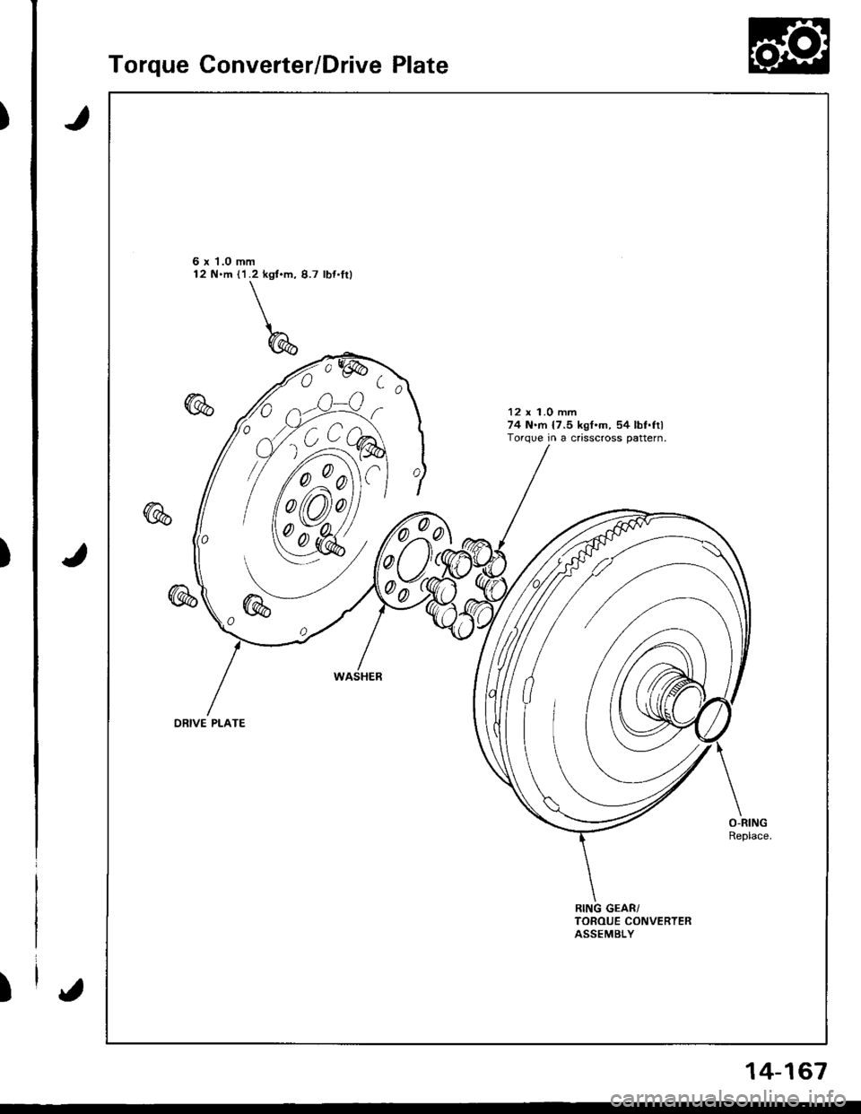
Torque Converter/Drive Plate
J
J
6 x 1.0 mm12 N.m ('l.2 kgt.m, 8.7 lbt.fil
12 x 1.0 mm74 N.rn {7.5 kgf.m, 54 lbf.filTorque in a crisscross pattern.
0
00
ORIVE PLATE
{
14-167
Page 584 of 1681
Transmission
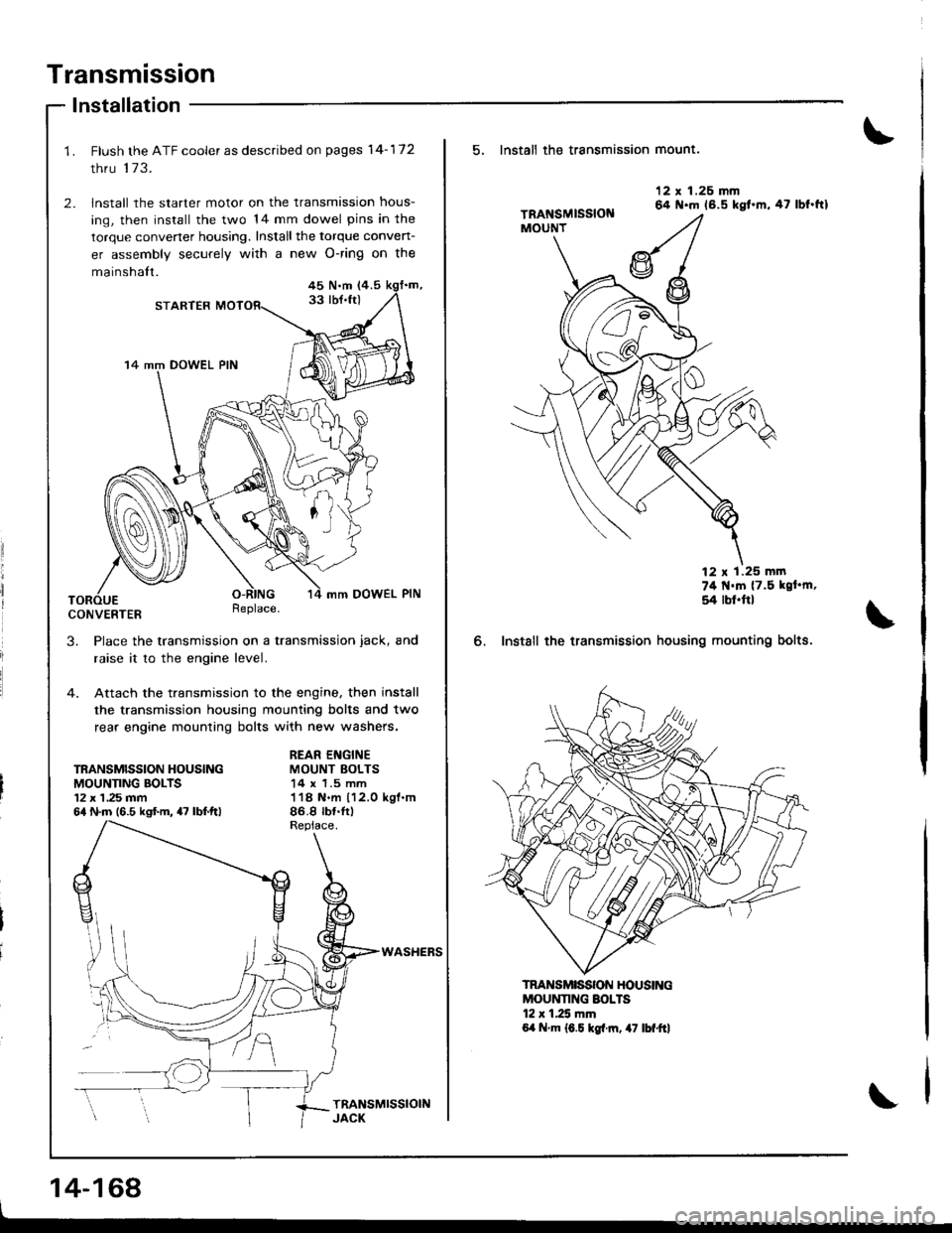
lnstallation
Flush the ATF cooler as described on pages 14-172
thru 173.
lnstall the starter motor on the transmission hous-
ing, then install the two 14 mm dowel pins in the
torque convener housing. Install the torque conven-
er assembly securely with a new O-ring on the
mainshalt.45 N.m (4.5
33 lbJ.ft)STARTER
14 mm DOWEL PIN
mm DOWEL PIN
CONVERTERReplace.
3. Place the transmission on a transmission jack, and
raise it to the engine level.
4. Attach the transmission to the engine, then install
the transmission housing mounting bolts and two
rear engine mounting bolts with new washers.
TRANSMISSION HOUSINGMOUNNNG BOLTS12 x 1 ,25 mm64 N.m (6.5 kgf.m, 47 lbf.ftl
REAR ENGINEMOUNT BOLTS14 x 1.5 mm118 N.m 112.0 kgl.m86.8 rb{.tr)
WASHEFS
14-168
5. Install th€ transmission mount.
6. Instsll the transmission
12 x 1.26 mm64 N.m 16.5 kgt.m,47 lbf.ftl
74 t{'m {7.5 kgt'm,
54 rbl.ftl
housing mounting bolts.
MOUNNNG SOLTS12 r 1.25 mm6,t N.m 16.5 kgl.rn, 47 lbf"ftl
TRANSMISSON HOUSING
Page 585 of 1681
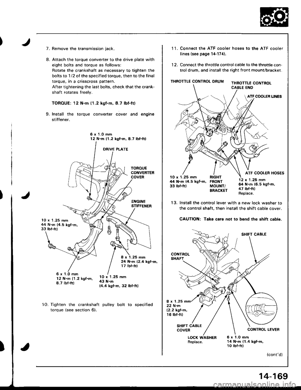
7.
10 x 1.25 mm1+4 N.m (4.5 kgt.m,33 tbf.ft)
TOROUECONVERTERCOVER
EI{GINESTIFFEI{ER
I x 1.25 mm24 N.m 12.4 kgf.m,17 rbf.ftl
8.
Remove the transmission jack.
Attach the torque converter to the drive plate with
eight bolts and torque as lollows:
Rotate the crankshatt as necessary to tighten the
bolts to 1/2 of the specified torque, then to the final
torque, in a crisscross pattern.
After tightening the last bolts, check that the crank-
shaft rotates freely.
TOROUE: 12 N.m (1.2 kgf.m. 8.7 lbf.ft)
Install the torque converter cover and engine
stitfener.
6 x 1.0 mm12 N'm l'1.2 kgl.m,8.7 lbl.ftl
ORIVE PLATE
9.
6 x '1.0 mm12 N'm ('1.2 kgf.m,8.7 tbt.fr)
l0 x 1.25 mm43 N.m{4.4 kgf.m, 32 lbl.ftl
10.Tighten the crankshaft
torque (see section 6).
pulley bolt to specified
)
1 1. Connect the ATF cooler hoses to the ATF cooler
lines (see page 14-174).
12. Connect the throttle control cable to the throtrle con,
trol drum, and installthe right front mount/brackel.
THROTTLE CONTROL DRUMTHROTTLE CONTROLCABLE END
ATF COOLER UNES
ATF COOLER HOSESlO x 1.25 mm RIGHT44 N.m 14.5 kgf.m, FRONT33 tbf.ft) MoUNT/BRACKET
13.
LOCK WASHERReplace.6 x 1.0 mft14 N.m (1.4 kgt.m,10 tbf.fr)
12 x 'l ,25 nn64 N.rh 16.5 kgf.m,47 tbt.ft)Replace.
SHIFT CABLE
CONTROL LEVER
(cont'dl
Install the control lever with a new lock washer to
the control shalt, then installthe shift cable cover.
CAUTION: Take care not to b6nd the shitt cable.
8 x 1.2522 N-m12.2 kgt.n.'t6 tbl.tr,
SHIFT CABLECOVER
14-169
Page 613 of 1681
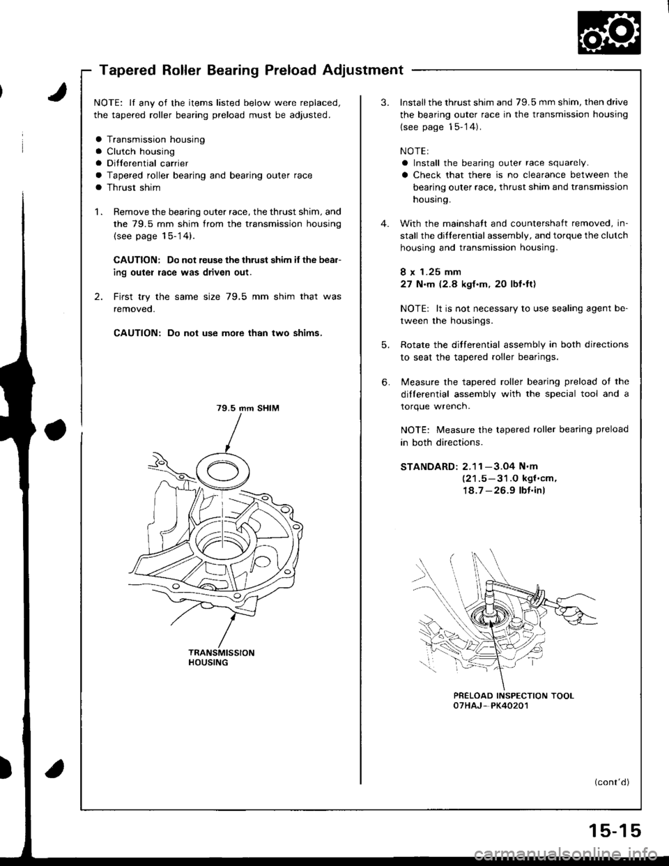
Tapered Roller Bearing Preload Adjustment
NOTE: lf any of the items listed below were replaced,
the tapered roller bearing preload must be adjusted.
a Transmission housing
a Clutch housing
a Ditferential carrier
a Tapered roller bearing and bearing outer race
a Thrust shim
1 . Remove the bearing outer race, the thrust shim, and
the 79.5 mm shim from the transmission housing
(see page 15-14).
CAUTION: Do not reuse the thrust shim if the bea.-
ing outer race was driven out-
2. First try the same size 79,5 mm shim that was
removeo.
CAUTION: Do not use more than two shims,
79.5 mm SHIM
HOUSING
3.Install the thrust shim and 79.5 mm shim, then drive
the bearing outer race in the transmission housing
{see page 15-'14).
NOTEI
a Install the bearing outer race squarely.
a Check that there is no clearance between the
bearing outer race, thrust shim and transmission
housing.
With the mainshatt and countershaft removed, in-
stall the dillerential assembly, and torque the clutch
housing and transmission housing.
8 x 1.25 mm
27 N.m (2.8 kgf.m. 2O lbf.ft)
NOTE: lt is not necessary to use sealing agent be-
tween the housings.
Rotate the ditferential assembly in both directions
to seat the tapered roller bearings.
Measure the tapered roller bearing preload ot the
dilferential assembly with the special tool and a
torque wrench.
NOTE: Measure the tapered roller bearing preload
in both directions.
STANDARD: 2.1 1 -3.O4 N'm
(21.5-31.O kgf'cm,
18.7 -26.9 lbt.inl
PRELOAD INSPECTION TOOL07HAJ-PK40201
(cont'd)
6.
5-1
Page 616 of 1681
Differential (818C5 engine)
SpecialTools .......... ........... 15-20
Limited Slip Differential
Description ..................... 15-21
OperationalGheck ......... 15-23
Rotating Torque Gheck .15-23
lffustrated Index .......... ..15-24
Tapered Roller Bearing Preload
Adjustment ................. 15-25
Page 619 of 1681
Limited Slip Differential (B18C5 engine)
Description (cont'd)
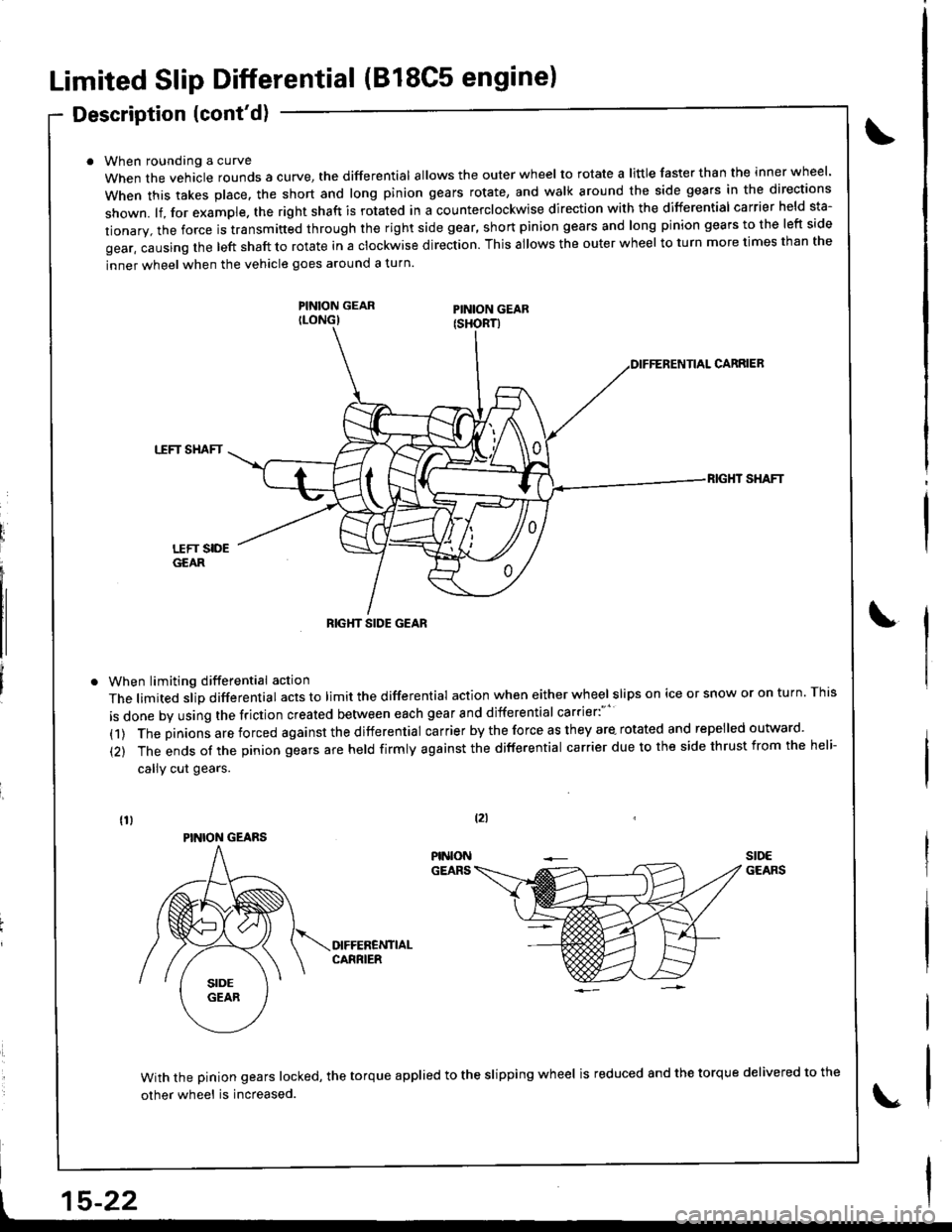
When roundang a curve
When the vehacle rounds a curye, tne differential allows the outer wheel to rotate a little faster than the inner wheel.
when this takes p|ace. the short and |ong pinion gears rotate, and wa|k around the side gears in the directions
shown. lf, for example. the right shaft is rotated in a counterclockwise direction with the differential carrier held sta-
tionary, the force is transmitted through the right side gear, short pinion gears and long pinion gears to the left side
gear, causing the left shaft to rotate in a clockwise direction. This allows the outer wheel to turn more times than the
inner wheel when the vehicle goes around a turn.
PINION GEARILONG)
When limiting differential action
The limited slip differential acts to limit the differential action when either wheel slips on ice or snow or on turn. This
is done by using the friction created between each gear and differential carrier:"''
(1) The pinions are forced against the differential carrier by the force as they are- rotated and repelled outward.
(2) The ends of the pinion gears are held firmly against the differential carrier due to the side thrust from the heli-
callY cut gears.
CARRIEB
TTFT SHAFT
RIG}IT SHAFT
With the pinion gears locked, the torque applied to the slipping wheel is reduced 8nd the torque delivered to the
other wheel is increased.
tzl
t15-22
RIGHT SIDE GEAR
PINION GEARS
Page 620 of 1681
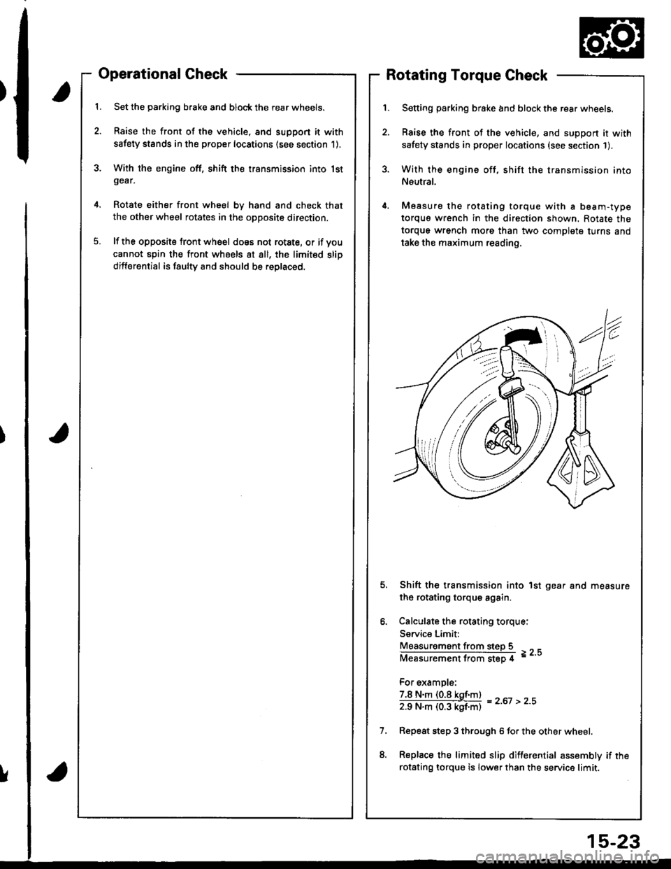
Operational Check
Set the parking brake and block the rear wheels.
Raise the front of the vehicle, and support it with
safety stands in the proper locations (see section 1).
With the engine off, shift the transmission into lstgear,
Rotate either front wheel bv hand and check that
the other wheel rotates in the opposite direction.
lf the opposite tront wheel does not rotste, or if voucannot spin the front wheels at all, the limited slip
differential is faulty and should be roplaced.
Rotating Torque Check
Setting parking brake and block the rear wheels.
Raise the front of the vehicle, and support it with
safety stands in proper locations (see section 1).
With the engine off, shift the transmission into
Neutral.
Measure the rotating torque with a beam-type
torquo wrench in the direction shown, Rotate the
torque wrench morg than two complete turns and
take the maximum reading.
Shift the transmission into 1st gear and measure
the rotating torque again.
Calculate the rotating torque:
Service Limit:
Measur€ment from steD 5
Measurementfrom step 4 =--
For example:
7.8 N.m (0.8 kgf.m)
zg N"ll (03 kgf'ntl = z'ot > z''
Repeat step 3 through 6 for the other wheel.
Replace the limited slip differential assembly if the
rotsting lorque is lower than the service limit.
!
15-23