Flywheel HONDA INTEGRA 1998 4.G Workshop Manual
[x] Cancel search | Manufacturer: HONDA, Model Year: 1998, Model line: INTEGRA, Model: HONDA INTEGRA 1998 4.GPages: 1681, PDF Size: 54.22 MB
Page 147 of 1681
I
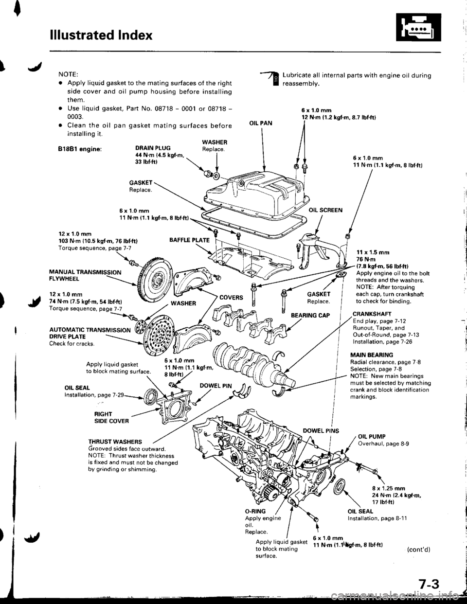
lllustrated Index
INOTE:
. Apply liqujd gasket to the mating surfaces ot the right
side cover and oil pump housing before installing
them.
. Use liquid gasket,
0003.
. Clea n the oil pan
installing it.
B18Bl engine:
Part No. 087'18 - 0001 or 08718 -
gasket mating surfaces before
Lubricate all internal parts with engine oil during
reassemDly.
6x1.0mm12 N.m {1.2 kg{.m,8.7 lbt.ft}
6x1.0mm11 N.m 11.1 kg'f.m,8 lbt.ftl
OIL SCREEN
DEAIN PLUG4il N.m 14.5 kgt m,33 tbtft)
BAFFLE PLATE
6x1.0mm1'l N.m (1.1 kgt.m,8 rbr.ftl
OIL PAN
O.FING
CAP
DOWEL PINS
WASHERReplace.
GASKETReplace.
6x1.0mm11 N.m (1.1 kgl.m, 8 lbl.ft)
12 x 1.0 mm103 Nm 110.5ks{.m,76lbf.ft}
MANUAL TRANSMISSIONFLYWHEEL
12 x 1.0 mm74 N.m 17.5 kgf.m,54lbf.tr)Torque sequence, page 7-7
AUTOMATIC TRANSMISSION
WASHERcovERsGASKETReplace.
11 x 1.5 mm76 N.m17.8 kgt m, 56 lbtft)Apply engine oilto the boltthreads and the washers.NOTE: After torquingeach cap, turn crankshaftto check for binding.
ORIVE PLATECheck for cracks.
Apply liquid gasketto block mating surface.
CRANKSHAFTEnd play, page 7-12Runout, Taper, andOut-of'Round, page 7-13Installation, page 7-26
MAIN AEARINGRadialclearance, page 7 8Selection, page 7'8NOTE: New main bearingsmust be selected by matchingcrank and block identificationmarkrngs.
I
i
OIL SEALlnstallation, page 7
RIGHTSIDE COVER
THRUST WASHERSGrooved sides face outward.NOTE: Thrust washer thicknessis fixed and must not be changedby grinding or shamming.
8 x 1.25 mm21 N..n l2.1kga'r,�,17 tbf.ft)
OIL SEALInstallation, page 8-1 1Apply engineorl.Replace.
Apply liquid gasket
to block matingsurface,
6x1.0mm11 N.m t1.lilh{.m,I lbf.ft}(cont'd)
Page 152 of 1681
/
li
l
Main Bearings
Clearance
2.
3.
1.
4.
To check main bearing-to-iournal oil clearance,
remove the main caps and bearing halves.
Clean each main iournal and bearing half with a
clean shop towel.
Place one strip of plastigage across each main iour-
na l-
NOTE: lf the engine is still in the car when you bolt
the main cap down to check clearance, the weight
of the crankshaft and flywheel will flatten the plasti'
gage further than just the torque on the cap bolt,
and give you an incorrect reading. For an accurate
reading, support the crank with a jack under the
counterweights and check only one bearing at a
trme.
Reinstall the bearing caps and cap bridge (B18C1,
B18C5 engines only)then torque the bolts.
Bl8Bl engine: 77 N'm (7.8 kgt.m.56lbf.ft)
B18Cl,818C5 engines:
No. 1,5 cap bolts 73 N.m (7.4 kgf.m,56lbnftl
No. 2. 3, 4 cap bolts 64 N.m {6.5 kgf m. 49 lbf ftl
NOTE: Do not rotate the crankshaft during inspec-
tro n.
Remove the cap bridge (818C1, 818C5 engines
only), caps and bearings again, and measure the
widest part of the plastigage.
Main Bearing-to-Journal Oil Clearance:
Standard lNew):
No. 1, 2, 4, 5: 0.024 - 0.042 mm
10.0009 -0.0017 in)
Service Limit:0.050 mm (0.0020 in)
No.3:0.030 - 0.048 mm
10.0012 - 0.0019 inl
Service Limit:0.060 mm {0.0024 inl
PLASTIGAGE STRIP
lf the plastigage measures too wide or too narrow,
{remove the engine if it's still in the car), remove the
crankshaft, and remove the upper half of the bear-
ing. lnstall a new, complete bearing with the same
color code (select the color as shown in the right
column), and recheck the clearance.
CAUTION: Do not file, shim. or scrape the bearings
or the caps to adiust clearance.
lf the plastigage shows the clearance is still incor-
rect, try the next larger or smaller bearing (the color
listed above or below that one), and check again.
NOTE: lf the oroDer clearance cannot be obtained
by using the appropriate larger or smaller bearings.
reolace the crankshaft and start over.
Selection
CAUTION: lf the codes ale indecipherable because of
an accumulation oI dirt and dust, do not scrub them
with a wire bru6h or scraper. Clean lhem only with sol-
vent or detergent.
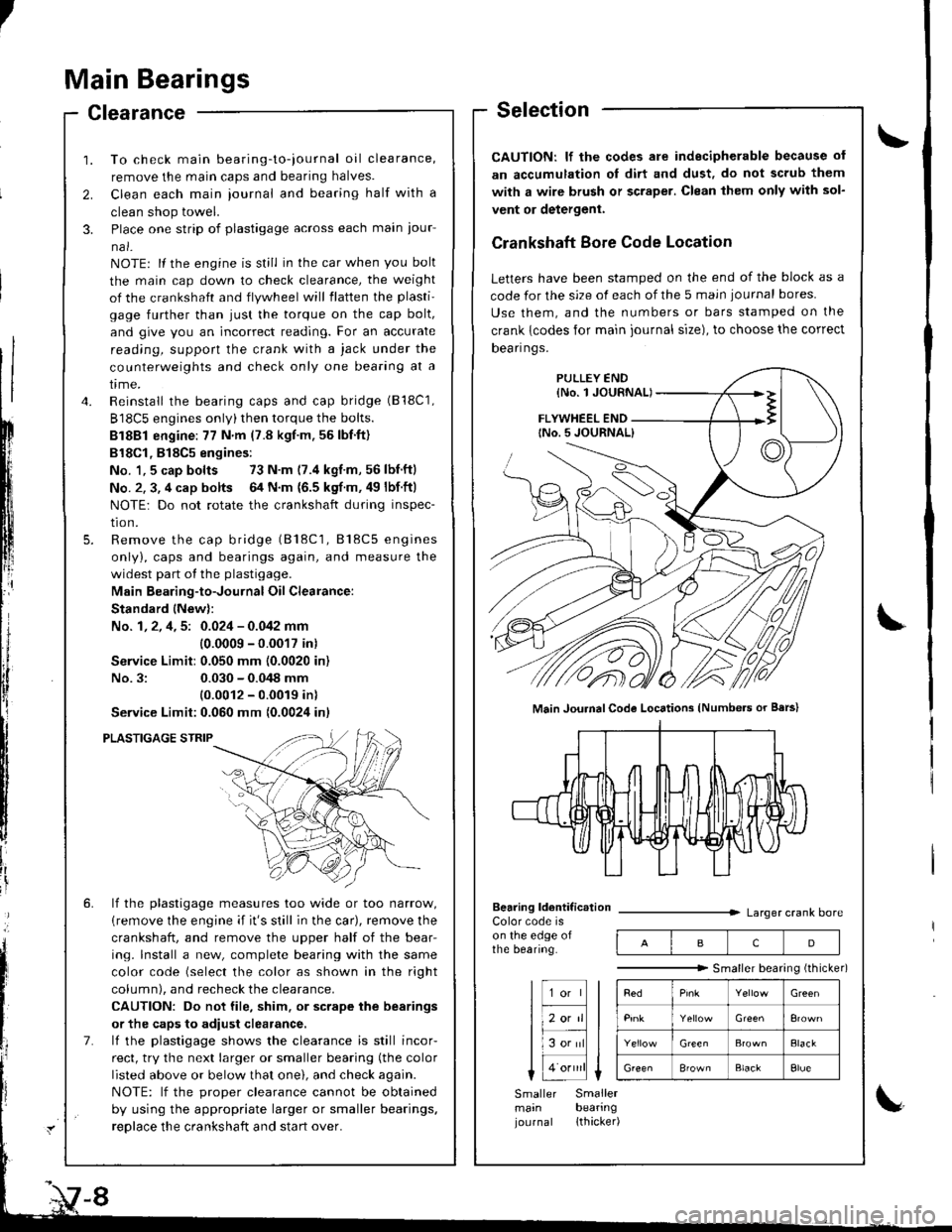
Crankshaft Bore Code Location
Letters have been stamped on the end of the block as a
code for the size of each of the 5 main iournal bores
Use them, and the numbers or bars stamped on the
crank {codes for main journal size), to choose the correct
Dean nqs,
FLYWHEEL END
Main JouhalCode Locations (Numbe.s or Bars)
Bearing ldentif ic.tionColor code ison the edge ofthe bearing.
Larger crank bore
acD
"""""""" Smallerbearingithicker)
Green
Elack
B'ownBlackElue
Smaller Smallermain bearingjournal lthacker)
Page 173 of 1681
Oil Seal
Installation
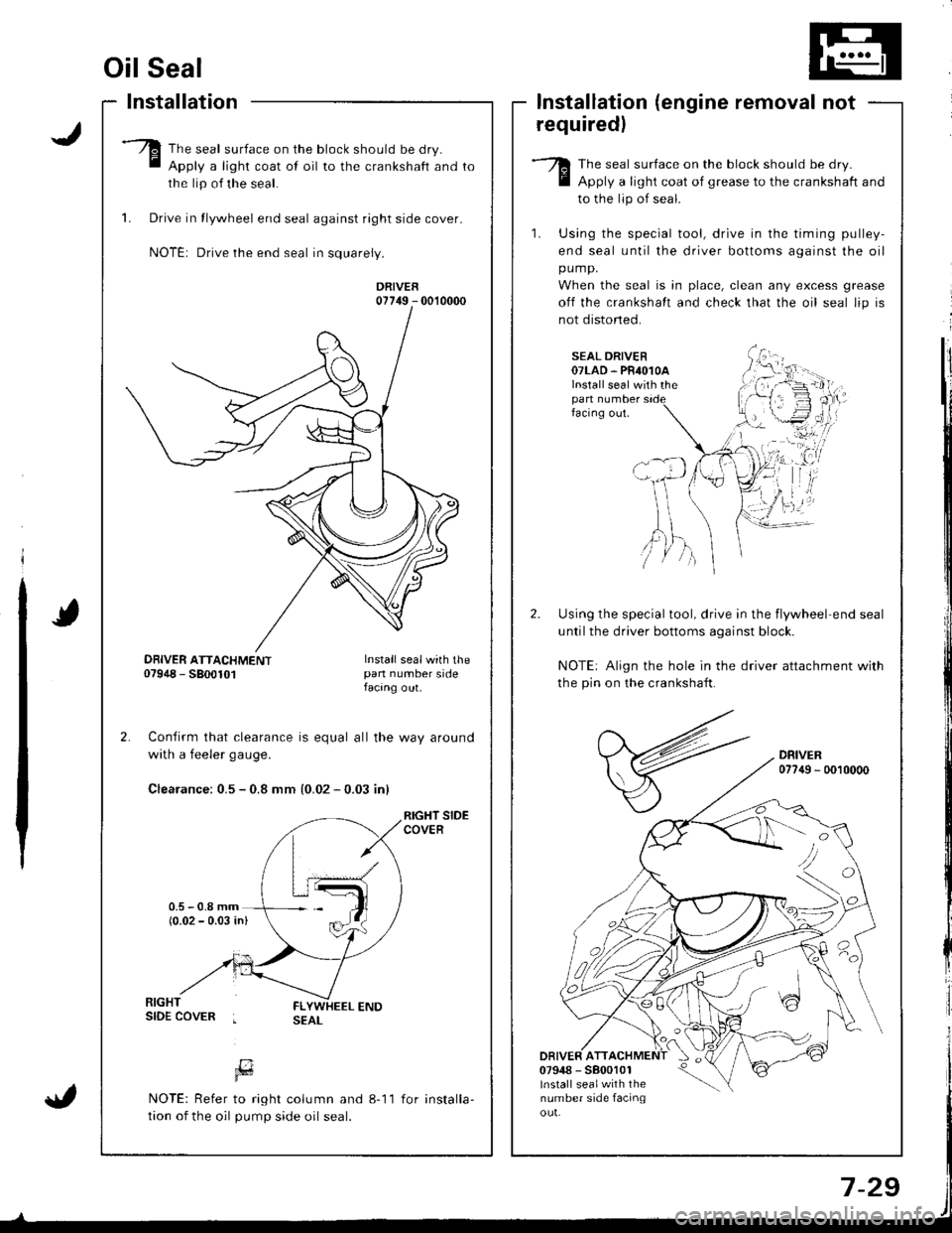
The seal surface on the block should be dry.
Apply a light coat of oil to the crankshaft and
the lip of the seal.
1. Drive in tlywheel end seal against right side cover.
NOTE: Drive the end seal in squarely.
DRIVER07749 - 0010000
Confirm that clearance is equal all the way around
with a feeler gaug€.
Clearance: 0.5 - 0.8 mm {0.02 - 0.03 inl
RIGHT SIDECOVER
lnstallation (engine removal not
requiredl
The seal surface on the block should be dry.
Apply a light coat of grease to the crankshaft and
to the lip of seal.
1. Using the special tool, drive in the timing pulley-
end seal until the driver bottoms against the oil
pump.
When the seal is in place, clean any excess grease
off the crankshalt and check that the oil seal lip is
not distoned.
SEAL DRIVER07LAD. PR4O1OAlnstall seal with thepan numberfacing out.
Using the special tool, drive in the flywheel end seal
untilthe driver bottoms aqainst block.
NOTE: Align the hole in the driver attachment with
the pin on the crankshaft.
DRIVER077{9 - 0010000
DRIVER ATT07948 - 5800101lnstall sealwith thenumber side facinqou!.
'tvA,)/ )
DBIVER ATTACHMENT07948 - 5800101Install sealwith thepan number sidefacang out.
[7Fd
NOTE: Refer to right column and 8-11
tion of the oil pump side oil seal.
for installa-
Page 358 of 1681
Clutch
Speciaf Tools ........ .'--"" 12-2
lflustrated Index ........ ".' 12-3
Clutch Pedal
Adjustment "..".""'...' 12-4
Clutch Master Cylinder
Removal/lnstallation -'.' 12-5
Slave Cylinder
Removal/lnstallation '..' 12-6
Pressure Plate
Removal/lnspection .'-.' 12-7
Clutch Disc
Removal/lnspection '...' 12-a
Flywheel, Flywheel Bearing
fnspection ' 12-9
Replacement .................'............. 1 2-9
Clutch Disc, Pressure Plate
lnstallation ................. 12-10
Release Bearing
Removal/lnspection "'.' 12-11
fnstaffation ".""".-'."'. 12-12
Page 360 of 1681
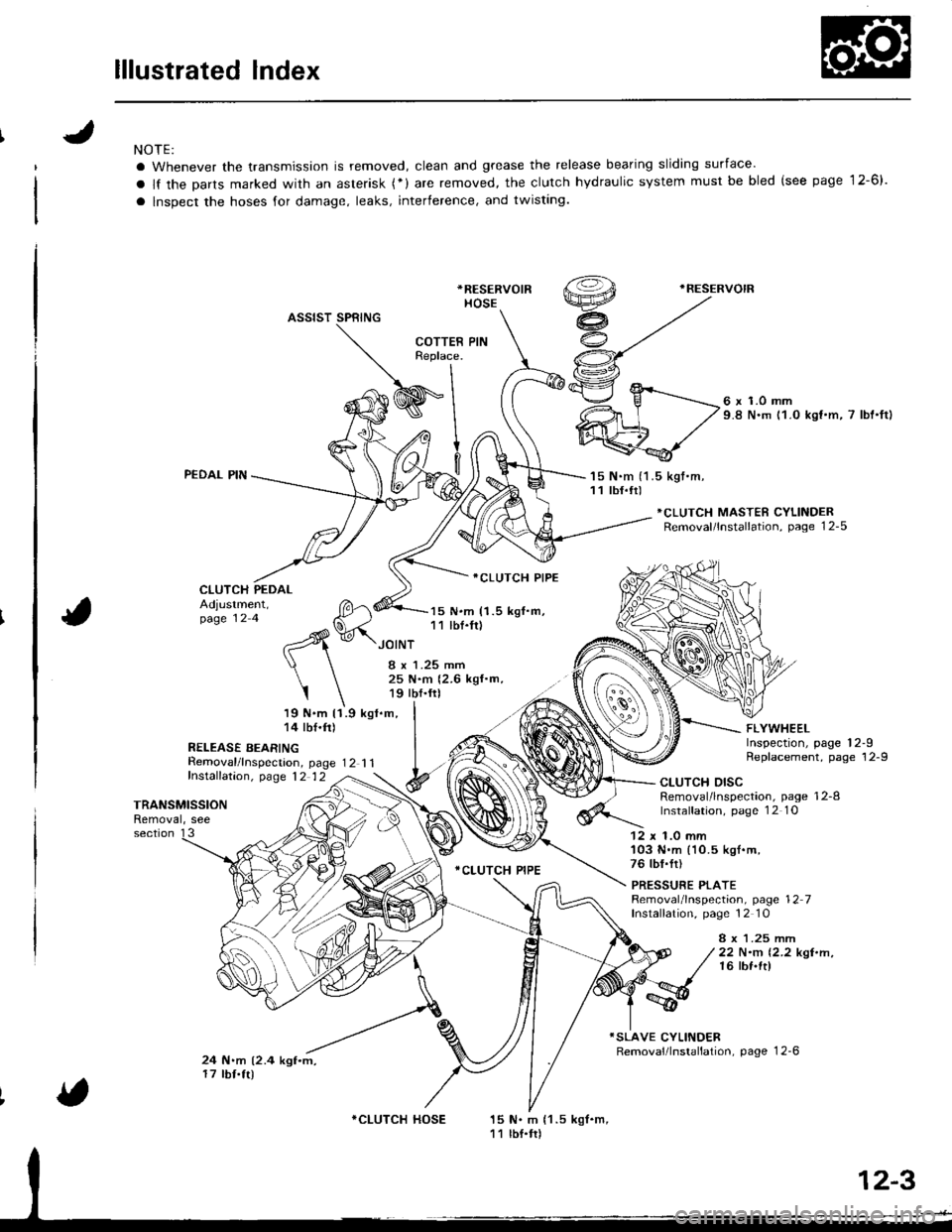
lllustrated Index
NOTE:
a Whenever the transmission is removed, clean and grease the release bearing sliding surface'
a lf the Darts marked with an asterisk (*) are removed, the clutch hydraulic system must be bled (see page 12-6).
a lnspect the hoses for damage, leaks, interference, and twisting.
*RESERVOIR
HOSE
.RESERVOIR
ASSIST SPRING
PEDAL PIN
CLUTCH PEDAL
Removal/lnspecrion, page 12 1 1fnstalfation, p,age 12 12
6 x 1.0 mm9.8 N.m 11.0 kst.m, 7 lbt'ftl
'15 N.m (1 .5 kgt.m,11 tbf.tr)
*CLUTCH MASTER CYLINDERRemoval/lnstallation, page 12-5
Adjustment,page 12 4
19 N.m 11.9 kgl.m,14 tbf.ft)
R€LEASE BEARING
15 N.m (1.5 kgf.m,11 lbf.fr)
ICLUTCH PIPE
.CLUTCH PIPE
FLYWHEELInspection, page 12-9Replacement, page 12-9
JOINT
I x 1.25 mm25 N.m {2.6 kgf.m,19 tbf.frl
I
TRANSMISSIONRemoval, see
CLUTCH DISCRemoval/lnspection, page 12-8lnstalfation, page 1 2 1O
section 1312 x 1.0 mm'103 N.m (10.5 kgl.m,76 tbf.fr)
PRESSURE PLATERemoval/lnspection, page 12 7Installation, page 12 10
8 x 1.25 mrr|22 N.m 12.2 kgt.n,16 lbf.ft)
24 N.m (2.4 kgf.m,17 tbf.tr)
15 N. m {1 .5 kgf.m,11 lbf.tr)
COTTERReplace.
I
WInl
9l
v.^- fl
*CLUTCH HOSE
Page 366 of 1681
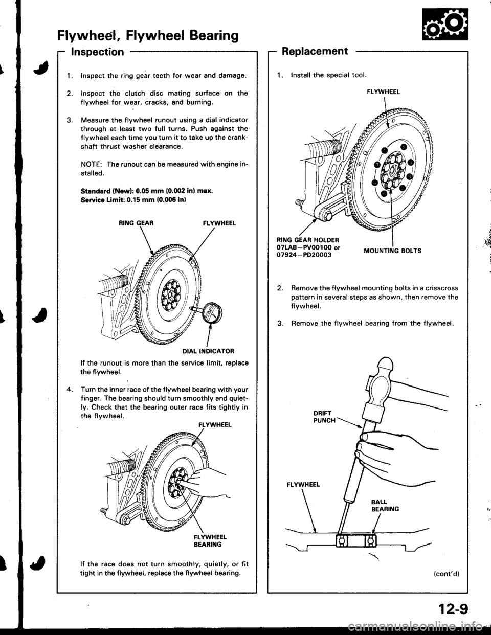
Flywheel, Flywheel Bearing
Inspection
t
',4
i
Replacement
1. Install the special tool.
MOUNTING BOLTS
Remove the flywheel mounting bolts in a crisscrosspattern in several steps as shown, then.emove the
Jlvwheel.
Bemove the flywheel bearing from the flywheel.
(cont'd)
FLYWHEEL
I
1.Inspect the ring gear teeth tor wear and damage.
Inspect the clutch disc mating surtace on the
flywheel for wear, cracks, and burning.
l\,reasure the flywheel runout using a dial indicator
through at least two full turns. Push agsinst the
Jlywheel each time you turn it to take up the crank-
shatt thrust washer clearance.
NOTE: The runout can ba measured with engine in-
stalled.
SiEndrrd (Ncw): 0.05 mm (0.002 inl max.
SerYicc Llmh: 0.15 mm (0.006 inl
DIAL INOICATOR
lf the runout is more than the service limit, reolace
the flywheel.
Turn the inner race of the flywheel bearing with your
tinger. The bearing should turn smoothly and quiet-
ly. Check that the bearing outer race tits tightly in
the flvwheel.
FLYWHEELBEARING
lf the race does not turn smoothly, quietly, or tit
tight in the flywheel, replace the flywheel bearing.
4.
FLYWHEEL
12-9
Page 367 of 1681
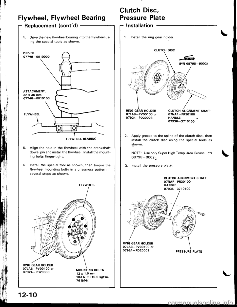
Clutch Disc,
Flywheel, Flywheel BearingPressure Plate
Replacement (cont'd)Installation
1. Install the ring gear holder.
CLUTCH DISC
1tti
CLUTCH ALIGNMENT SHAFT07NAF-PR30100HANDLE07936 -3710100
Apply grease to the spline ot the clutch disc, then
install the clutch disc using the special tools as
shown.
NOTE: Use only Super High Temp Urea Grease (P/N
o8798 9002).
3. Insrall the pressure Plate.
CLUTCH ALIGNMENT SHAFT07NAF-PR30100HANDLE07936-3710100
RING GEAR HOI-DER07LAB - PV001O0 or07924-PD20003
4. Drive the new flywheel bearing into the flywheel us-
ing the special tools as shown.
DRIVER07749 -0010000
FLYWHEEL
Align the hole in the llywheel with the crankshalt
dowel pin and installthe flywheel. Installthe mount-
ing bolts fingertight.
Install the special tool as shown, then torque the
flvwheel mounting bolts in a crisscross pattern in
several steps as shown-
6.
ATTACHMENT,32x35mm07746 0010100
5.
RING GEAE HOLDER07LAB-Pv00100 or07924-PD20003MOUNTING BOLTS12 x 1.0 mm103 N.m (10.5 kgf .m,
76 tbt.frl
FLYWHEEL BEARING
FLYWHEEL
6!-o
&#,oit
12-10
PRESSURE PLATE
Page 420 of 1681
Description
\J
t{
{
14-3
The automatic transmission is a combination of a 3-element torque converter and triple-shalt electronically controlled
automatic transmission which provides 4 speeds forward and 1 speed reverse. The entire unit is positioned in line with
the engrne.
Torque Converter, Gears, and Clutches
The torque converter consists of a pump, turbine, and stator, assembled in sigle unit. The torque converter is connected to
the engine crankshaft so they turn torether as a unit as the engine turns. Around the outside of the torque convener is a
ring gear which meshes with the starter pinion when the engine is being started. The entire torque converter assembly
serves as a flywheel while transmitting power to the transmission mainshaft.
The transmission has three parallel shafts; the mainshaft. the countershaft, and the sub shaft. The mainshaft is in-line with
the engine crankshaft.
The mainshaft includes the 1st, and 2ndl4th clutches,and gear for 3rd, 2nd, 4th, reverse, and 1st. (3rd gear is integral with
the mainshaft, while reverse gear is integral with the 4th gear.)
The countershaft includes the 3rd clutch and gears for 3rd,2nd, 4th, reverse, 1st, and parking. Reverse and 4th gears can
be loched to the countershaft at its center,providing 4th gear or reverse, depending on which way the selector is moved.
The sub-shaft includes the 1st-hold clutch and gears fo 1st and 4th.
The gears on the mainshaft are in constant mesh with those on the countersahft and sub-shaft.When certain combinations
of gears in the transmission are engaged by clutches. power in transmitted from the mainshaft to the countershaft via the
sub-shaft to orovude oil, lo'1. E, E. and E.
Electronic Control
The electronic control svstem consists of the Transmission Control Module (TCM), sensors, and four solenoid valves.
Shilting and lock-up are electronically controlled for comfortable driving under all conditions.
The TCM is located below the dashboard, behind the lelt side kick panel on the driver's side.
Hydraulic Control
The valve bodies include the main valve body, the secondary valve body, the regulator valve body, the serbvo body, and
the lock-up valve body, through the respective separator plates, They are bolted to the torque converter housing,
The main valve body contains the manual valve, the 1-2 shift valve, the 2-3 shitt valve, the Clutch Pressure Control
lCPC) valve, the 4th exhaust valve, the reliel valve, and the ATF pump gears.
The secondary valve body contains the 4-3 kick-down valve, the 3-2 kick-down valve, the 2-3 orifice control valve, the
3-4 shift valve, the orilice control valve, the modulator valve, and the servo control valve.
The regulator valve body contains the pressure regulator valve, the lock-up control valve, the torque converter check
valve, and the cooler check valve.
The servo body contains the servo valve, which is integrated with shift fork shaft, the throttle valve B, and the accumula-
tors.
The lock-up valve body contains the lock-up shift valve and the lock-up timing B valve, and is bolted to the regulator valve
ooqy.
Fluid from the regulator passes through the manual valve to the various control valves.
Shift Control Mechanism
Input to the TCM from various sensors located throughout the car determines which shift control solenoid valve should
be activated. Activating a shitt control solenoid valve changes modulator pressure, causing a shift valve to move. This
pressurizes a line to one ol the clutches, engaging that clutch and its corresponding gear.
Lock-uD Mechanism
In @ position, in 2nd, 3rd and 4th, and @ position in 3rd, pressurized fluid can be drained lrom the back oI the tor-
que converter through a fluid passage, causing the lock-up piston to be held against the torque converter cover. As this
takes place, the mainshaft rotates at the same speed as the engine crankshaft. Together with hydraulic control, the TCM
optimizes the timing of the lock-up mechanism.
The lock-up valves controlthe range of lock-up according to lock-up control solenoid valves A and B, and throttle valve B.
When lock-up control solenoid valves A and B activate, modulator pressure changes. Lock-up control solenoid valves
A and B are mounted on the torque converter housing, and are controlled by the TCM.
(cont'd)
Page 1135 of 1681
Starting System
Starter Test (cont'dl
Check Cranking rpmr
Engine speed during cranking should be above 1OO rpm.
lJ speed is too low, check for:
a Loose batlery or starter terminals
a Excessively worn starter brushes
a Open circuit in commutator segments
a Dirty or damaged helical spline or drive gear
a Defective drive gear overrunning clutch
Check Starter Disengagement:
Press the clutch pedal all the way in (M/T), turn rhe igni
tion switch to "lll" and release to "11".
The starter drive gear should disengage from the flywheel
or torque converter ring gear when you release the key.
It the drive gear hangs up on the flywheel or torque con-
verter ring gear, check for:
a Solenoid plunger and switch mallunction
a Dirty drive gear assembly or damaged overrunning
clutch
5. Check for an open in the BLK/WHT wire circuit be
tween the starter and ignition switch, and con-
necrors,
6. Check the ignition switch (see page 23-71).
7. On cars with automatic transmission, check the A/Tgear position switch (neutral position switch) and
connector. On cars with manualtransmission, check
the starter cut relay, clutch interlock switch, and
connectors.
NOTE: Check the No. 42 (40 A) fuse in the under,hoodfuse/relay box for the starter cut relay.
Check Jor Wear and Damage:
The starter should crank the engine smoothly and stead,ily. lf the starter engages, but cranks the engine errati
cally, remove it. Inspect the starter, drive gear, andllywheel or torque converter ring gear lor damage.
a Check the drive gear overrunning clutch for binding
or slipping when the armature is rotated with the drivegear held. Replace the gears i{ damaged.
Check CJanking Voltage and Current Draw:
Cranking voltage should be no less than 8.O volts.
Current draw should be no more than * amperes.* 1.2 kW: 27O A
1 .4 kW: 360 A
It cranking voltage is too low, or current draw too high,check for:
a Dead or low charged batterya Open circuit in starter armature commutator segmentsa Starter armalure dragging
a Shorted armature windinga Excessive drag in engine
Page 1142 of 1681
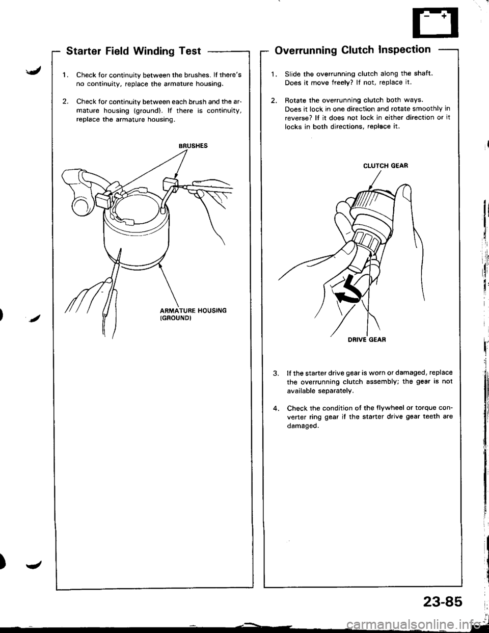
BRUSHES
Startel Field Winding Test
Check for continuity between the brushes. lf there's
no continuity. replace the armature housing.
Check for continuily between each brush and the ar-
mature housing (ground). lf there is continuity,
replace the armature housing.
Overrunning Clutch InsPection
Slide the overrunning clutch along the shaft.
Does it move freely? It not, replace it.
Rotate the overrunning clutch both ways.
Does it lock in one direction and rotate smoothly in
reverse? It it does not lock in either direction or it
locks in both directions, repl8c€ it,
lf the starter drive gear is worn or damaged, replace
the overrunning clutch assembly; the gear is not
available separately.
Check the condition ot the flywheel or torque con-
vener ring gear it the starter drive gear teeth are
damaged.
/
J
CLUTCH G€AR
DRIVE GEAR
23-85
l'l- ,-----_ -'l