drain bolt HONDA INTEGRA 1998 4.G User Guide
[x] Cancel search | Manufacturer: HONDA, Model Year: 1998, Model line: INTEGRA, Model: HONDA INTEGRA 1998 4.GPages: 1681, PDF Size: 54.22 MB
Page 690 of 1681
Power Steering
Gearbox
Removal
NOTE: Using solvent and a brush, wash any oil and dirt
off the valve body unit, its lines, and the end if the gear-
box. Blow dry with compressed air.
l. Drain the power steering fluid as described on page
11-21.
2. Raise the front of vehicle, and support on safety
stands in the proper locations (see section 1).
3. Remove the front wheels.
4. When the vehicle is equipped with the SBS airbag
system, remove the steering wheel (see page 17-
24t.
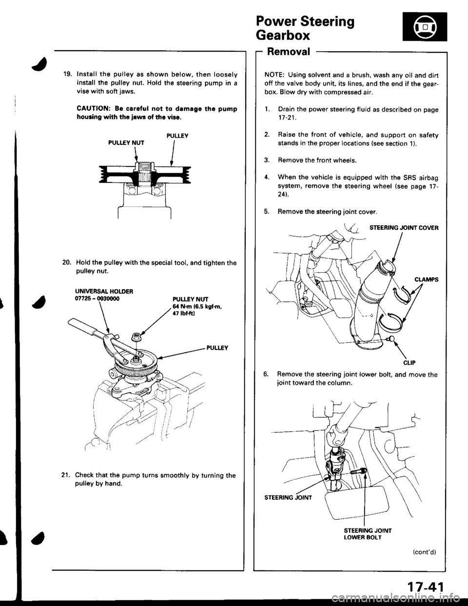
5. Remove the steering
6. Remove the steering joint lower bolt, and move the
ioint toward the column.
STEERING JOINTLOWER SOI-T
(cont'd)
19. Install the pulley as shown below, then loosely
install the pulley nut. Hold the steering pump in a
vise with soft jaws.
CAUTION: Be carelul not to damlge tho pump
hou3ino with ths ilws of th6 vies.
Hold the pulley with the special tool, and tighten thepu ey nut.
ioint
Va
20.
PULI.IY NUT6,1 N.m {6.5 kgt m,47 lbf,ftl
'(
Check that the pump turns smoothly by turning thepulley by hand.
.-l
21.
PULLEY
UNIVERSAL HOLDER
CLIP
17-41
Page 694 of 1681
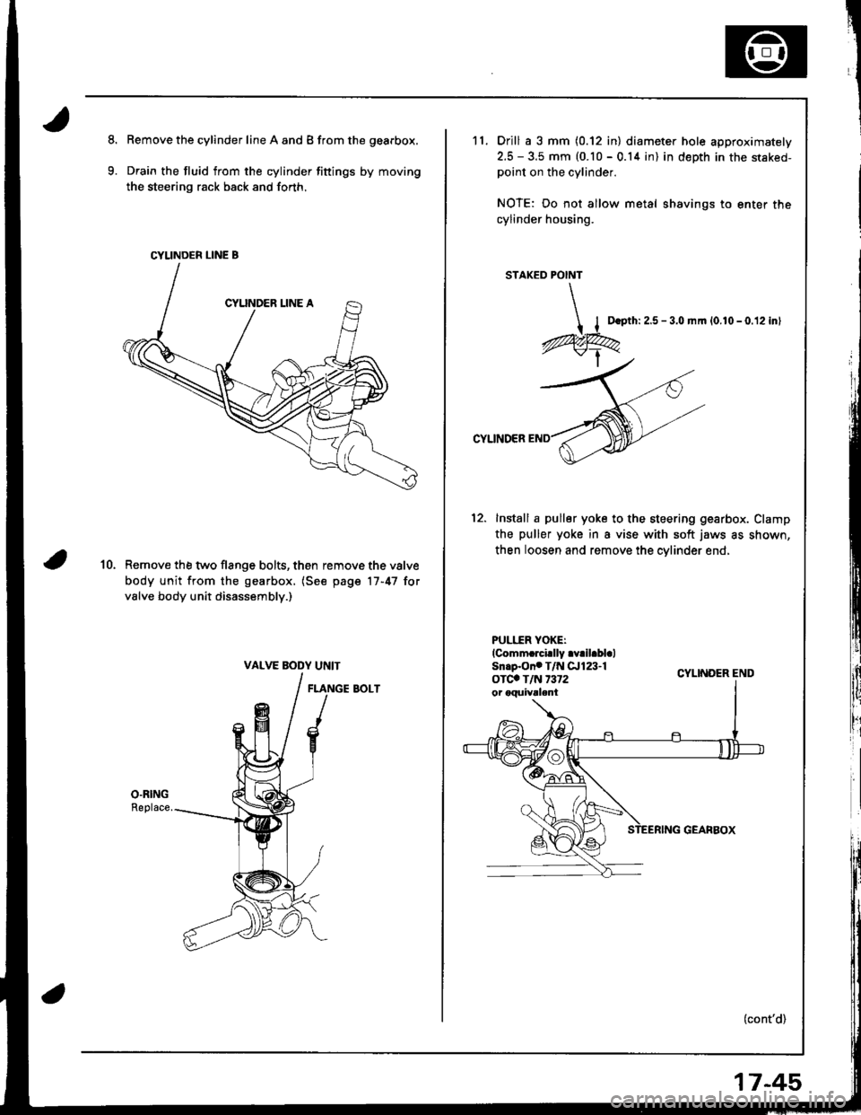
8.Remove the cylinder line A and B from the gearbox.
Drain the fluid from the cylinder fittings by moving
the steering rack back and forth.
Remove the two flange bolts, then remove the valve
body unit from the gearbox, (See page 17-47 for
valve body unit disassembly.)
FLANGE BOLT
10.
CYLINDER LINE B
VAI.VE BODY UNIT
11.Orill a 3 mm (0.12 in) diameter hole approximately
2.5 - 3.5 mm (0.10 - 0.14 in) in depth in the staked-point on the cylinder.
NOTE: Oo not allow metal shavings to enter the
cylinder housing.
12. Install a puller yoke to the steering gearbox. Clamp
the puller yoke in a vise with soft jaws as shown,
then loosen and remove the cvlinder end,
CYLINDER END
STAKED POINT
\\
i D.pth:2.5 - 3.0 mm {0.10 - 0.'12 inl
re
17-45l
Page 893 of 1681
Moonroof
Troubleshooting
SymptomP.obable Cause
Clogged drain tube.
Gap between glass weatherstrip and roof panel
De{ectrve or improperly Installed glass weatherstrip
Gap between drain seal and rool panel.
Excessive clearance between glass weatherstrip and roof panel-
Loose motor.
Worn gear or bearing.
Cable assemblv deformed.
1
2
3
4
1
2
3
1.
Water leaks
Wind noise
Motor noise
Glass does not move, but motor
turns
Clutch out ol adiustment.
Foreign matter stuck between guide rail and slider'
lnner cable loose.
Cable assembly not attached properly
,l
2
3
4
Glass does not move and motor
does not turn (glass can be moved
with moonroof wrench)
1. Blown fuse.
2. Faulty switch.
3. Battery run down.
4. Delective motor.
5. Faulty relay.
Glass Height Adiustment
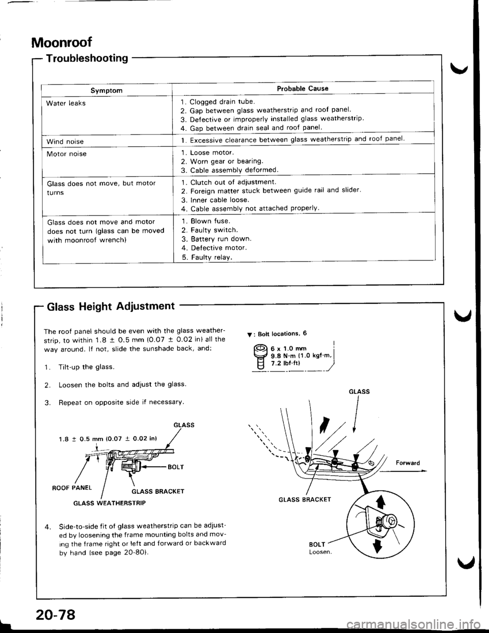
The roof panel should be even with the glass weather-
srrip, to within 1.8 t O.5 mm {O.07 t 0.02 in} all the
way around. lf not, slide the sunshade back, and:
1. Tilt-up the glass.
2. Loosen the bolts and adjust the glass.
3. Repeat on opposite side if necessary.
1.8 i 0.5 mm 10.07 i 0.02 inl
V : Boll locations, 6
]-
ROOF PANELGLASS BRACKET
Side-to-side iit of glass weatherstrip can be adJust-
ed by loosening the frame mounting bolts and mov-
ing the frame right or left and {orward or backward
by hand (see page 2O-8Oi.
GLASS BRACKETGLASS WEATHERSTRIP
{
$
I
!
20-78
Page 895 of 1681
Moonroof
Motor, Drain Tube and Frame Replacement
CAUTION: Be careful not to damage the seats, dash-
boa.d and other interior trim.
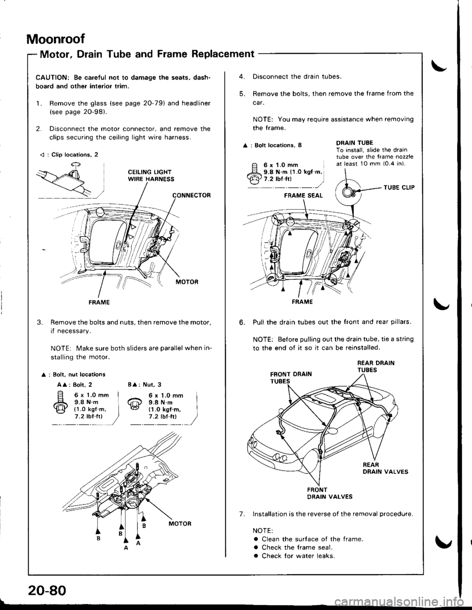
1. Remove the glass (see page 20-79) and headliner
{see page 2O-98}.
2. Disconnect the motor connector, and remove the
clips securing the ceiling light wire harness.
Remove the bolts and nuts, then remove the motor,
if necessary.
NOTE: Make sure both sliders are parallel when in-
stalling the motor.
3.
: Bolt, nut locations
A
: 8olt, 2
6x 1.0mm I9.8Nm L
Nut, 3
6 x 1.0 mm I9.4 N.m
BA:
6@{1.0 kgf7 .2 tbl:!)(1.O kgf m, I
1'�lIltl /
< : Clip locations, 2
4,
FRAME
Oisconnect the drain tubes.
Remove the bolts, then remove the lrame from the
car.
NOTE: You may require assistance when removing
the trame.
A : Bolt locations, 8
TUBE CLIP
FRAME SEAL
Pull the drain tubes out the front and rear pillars.
NOTE: Before pulling out the drain tube, tie a string
to the end of it so it can be reinstalled.
REAR DRAINTUBES
7. Installation is lhe reverse of the removal procedure.
NOTE:
a Clean the surtace of the frame.
a Check the lrame seal.
a Check tor water leaks.
DRAIN TUBETo install, slide the draintube over the {rame nozzleat least 10 mm i0.4 in).
-'
6 x 1.0 mm9.8 N.m 11.0 kgt m,7.2 tbf.fr)
FRAME
FRONTDRAIN VALVES
!
\"
20-80
\
v
Page 900 of 1681
)
Troubleshooting
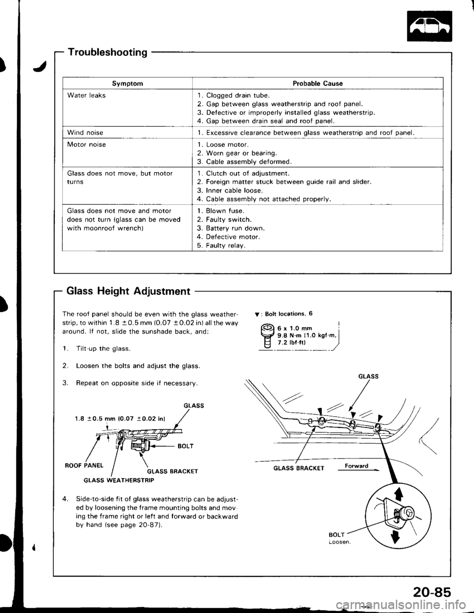
Glass Height Adjustment
The rooJ panel should be even with the glass weather
strip, to within 1.8 t 0.5 mm (O.O7 tO.O2 in) allthe way
around. It not, slide the sunshade back, and:
1. Tilt-up the glass.
2. Loosen the bolts and adjust the glass.
3. Repeat on opposite side if necessary.
1.810.5 mm {0.07 } 0.02 inl
Gr_ASS
4-(.'
ROOF PANELGLASS BRACKET
GLASS WEATHERSTRIP
4. Side-to-side fit oI glass weatherstrip can be adjust-
ed by loosening the frame mounting bolts and mov
ing the frame right or left and forward or backward
by hand (see page 20-87).
GLASS BRACKET
SymptomProbable Cause
Water leaks1. Clogged drain tube.
2. Gap between glass weatherstrip and roof panel.
3. Detective or improperly installed glass weatherstrip.
4. Gap between drain seal and roof panel.
Wind noise1. Excessive clearance between qlass weatherstriD and roof oanel.
Motor noiseI
2
3
Loose motor.
Worn gear or bearing.
Cable assembly deformed.
Glass does not move, but motor
turnS
1
2
3
Clutch out of adjustment.
Foreign matter stuck between guide rail and slider.
lnner cable loose.
Cable assembly not attached properly.
Glass does not move and motor
does not turn (glass can be moved
with moonroof wrench)
I
2
3
Blown fuse.
Faulty switch.
Battery run down.
Defective motor.
Faulty relay.5
{
s
I
20-85
Page 902 of 1681
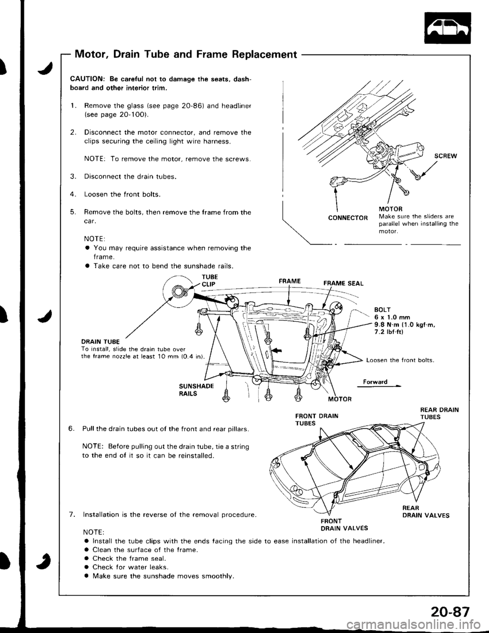
Motor, Drain Tube and Frame Replacement
J
J
CAUTION: Be ca.eful not to damage the seats, dash-
board and other interior trim,
1. Remove the glass (see page 2O-86) and headliner(see page 20- 1OO).
2. Disconnect the motor connector, and remove the
clips securing the ceiling light wire harness.
NOTE: To remove the motor, remove the screws.
3. Disconnect the drain tubes.
4. Loosen the front bolts.
5. Remove the bolts, then remove the frame from the
car.
NOTE:
a You may require assistance when removing the
f rame.
a Take care not to bend the sunshade rails.
TUBECLIP
CONNECTORMake sure the sliders areparallel when installing themotor.
FRAMEFRAME SEAL
DRAIN TUBETo Install, slide the drain tube overthe frame nozzle at least 10 mm (0.4 in).
EOLT6 x 1.0 mm9.8 N.m l1.O kgf .m,
7 .2 tbt.ltl
Loosen the front bolts,
Fo.ward
6.
7.
SUNSHADERAILS
Pull the drain tubes out of the front and rear pillars.
NOTE: Before pulling out the drain tube, rie a string
to the end oI it so it can be reinstalled.
Installation is the reverse ol the removal procedure.
NOTE:
a Install the tube clips with the ends {acing the side to ease
a Clean the surface of the frame.
a Check the frame seal.
a Check lor water leaks.
a Make sure the sunshade moves smoothly.
FRONTDRAIN VALVES
installation of the headliner.
Page 1044 of 1681
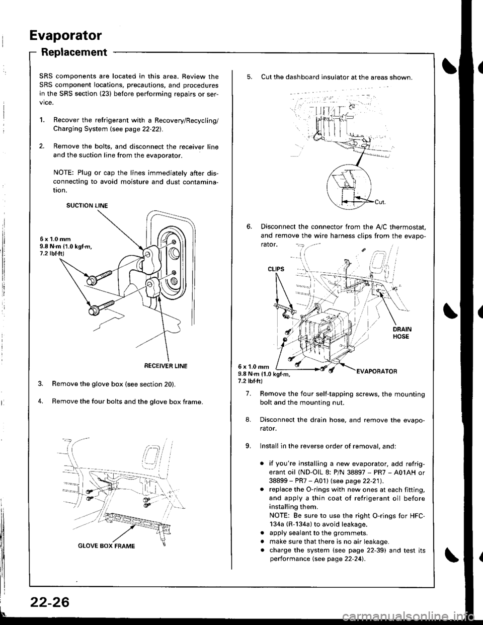
Evaporator
Replacement
Cut the dashboard insulato. at the areas shown.
Disconnect the connector from the A,,/C thermostat.
and remove the wire harness clips from the evapo-
rator.
6 x 1.0 rnm9.8 N.m 11.0 kgf.m,7.2 tbl.ft)
EVAPOBATOB
7. Remove the four self-tapping screws. the mounting
bolt and the mounting nut.
8. Disconnect the drain hose, and remove the evapo-
rator.
9, Install in the reverse order of removal, and:
. if you're installing a new evaporator, add refrig-
erant oil (ND-OlL 8: PiN 38897 - PR7 - A0IAH or
38899 - PR7 - A0 I I lsee page 22-21) .. replace the O-rings with new ones at each fitting,
and apply a thin coat of refrigerant oil before
installing them.
NOTE: Be sure to use the right O-rings tor HFC-
134a (R-134a) to avoid leakage.
. apply sealant to the grommets.
. make sure that there is no air leakage.. charge the system (see page 22-39) and test itsperformance {see page 22-24l�.
CLIPS
SRS components are located in this area. Review the
SRS component locations, precautions, and procedures
in the SRS section {23) before performing repairs or ser-
vice.
1. Recover the retrigerant with a Recovery/Recycling/
Charging System \see page 22-221.
2. Remove the bolts, and disconnect the receiver line
and the suction line from the evaporator.
NOTE: Plug or cap the lines immediately after dis-
connecting to avoid moisture and dust contamina-
UOn.
6x1.0mm9.8 N.m 11.0 kgf.m,1.2 tbi.ft)
Remove the glove box (see section 20).
Remove the four bolts and the glove box frame.4.
SUCTION LINE
RECEIVER LINE
22-26
Page 1049 of 1681
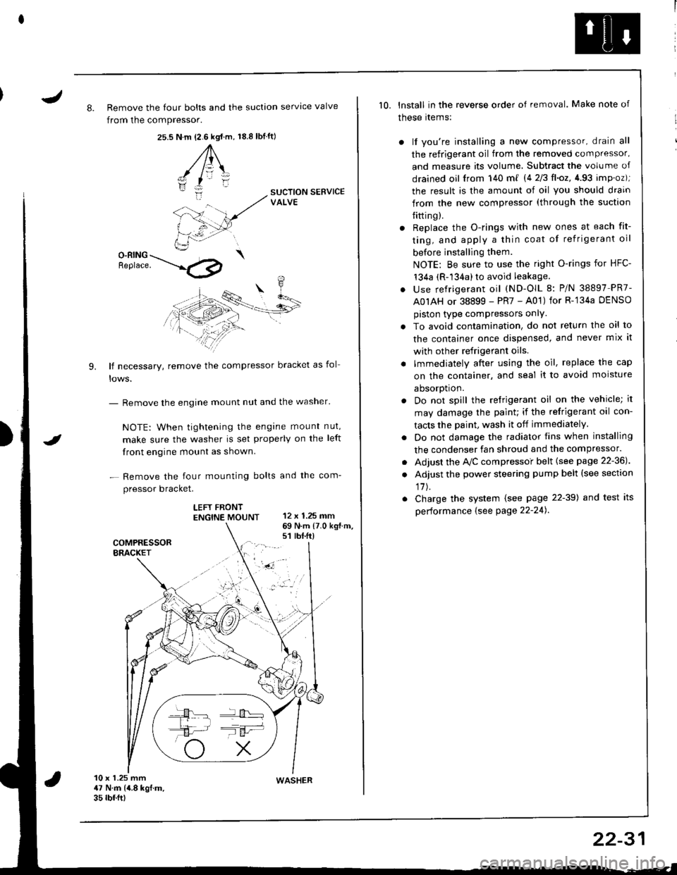
J8. Remove the four bolts and the suction servtce valve
from the compressor.
25.s18.8 tbf.ft)N.m {2.6 kgt.m,
A\
-/ l=\'zI
i:-
9.
SUCTION SERVICEVALVE
O-RING \Benrace. --'.l4p
lf necessary, remove the compressor bracket as fol
- Remove the engine mount nut and the washer'
NOTE: When tightening the engane mount nut,
make sure the washer is set properly on the left
front engine mount as shown.
- Remove the four mounting bolts and the com-
pressor bracket.
LEFT FRONTENGTNE MOUNT 12 x 1.25 mm
I
69 N.m {7.0 kg{.m.s1 rbt.ft)
10 x 1.25 mm47 N.m (4.8 kgf.m.35 rbf.ftt
10. lnstall in the reverse order of removal. Make note of
these rtems:
) lf you're installing a new compressor, drain all
the refrigerant oil from the removed compressor,
and measure its volume, Subtract the volume of
drained oil from 140 m{ 14 2/3ll.oz,4.93 imp.oz);
the result is the amount of oil you should drain
from the new compressor (through the suction
{itting).
r Replace the O-rings with new ones at each fit-
ting, and apply a thin coat of refrigerant oil
before installing them.
NOTE: Be sure to use the right O-rings for HFC-'t34a (R-134a) to avoid leakage.
. use refrigerant oil (ND-OlL 8: P/N 38897 PR7-
A0IAH or 38899 - PR7 - A01) for R-'134a DENSO
piston type compressors onlY.
. To avoid contamination, do not return the oil to
the container once dispensed, and never mix it
with other refrigerant oils.
. lmmediately after using the oil, replace the cap
on the container, and seal it to avoid moisture
aDsorDt|on.
. Do not spill the refrigerant oil on the vehicle; it
may damage the paint; if the refrigerant oil con-
tacts the Daint, wash it off immediately.
. Do not damage the radiator fins when installing
the condenser fan shroud and the compressor.
. Adjust the Ay'C compressoi belt {see page 22-36J
. Adjust the power steering pump belt (see section
17J.
. Charge the system (see page 22-39) and test its
performance {see Page 22-24).
WASHER
22-31
Page 1190 of 1681
I
Seat Belt Reminder
SystemLow Fuel lndicator
Indicator Light Test
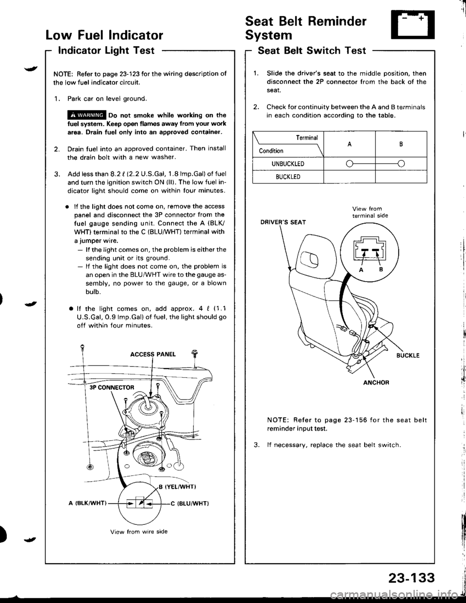
NOTE: Refer to page 23-123 for the wiring description of
the low fuel indicator circuit.
1. Park car on level ground.
@ oo not smoke whilc wolking on the
fuel system. Keep open tlames away from your work
area. Drain fuel only into an approved container.
2. Drain fuel into an approved container. Then install
the drain bolt with a new washer.
3. Add lessthan 8.2 t l2.2U.S.Gal, 1.8 lmp.Gal)of fuel
and turn the ignition switch ON {ll). The low fuel in-
dicator light should come on within lour minutes.
. lf the light does not come on. remove the access
panel and disconnect the 3P connector from the
fuel gauge sending unit. Connect the A (BLV
WHT) terminal to the C (BLU,/WHT) terminal with
a jumper wire.
- lf the Iight comes on, the problem is either the
sending unit or its ground.- lf the light does not come on, the problem is
an open in the BLU/WHT wire to the gauge as-
sembly, no power to the gauge, or a blown
bulb.
a lf the light comes on, add approx.4 ! (1.1
U.S.Gal. O.9 lmp.Gal) of fuel, the light should go
off within four minutes.
I
i
)
SeatSwitchTestBelt
1.Slide the driver's seat to the middle position. then
disconnect the 2P connector from the back of the
seat.
Check tor continuity between the A and B terminals
in each condition according to the table.
NOTE: Refer to page 23-156 for the seat belt
reminder input test,
3. lf necessary, replace the seat belt switch.
Terminal
c""dil----lB
UNBUCKLEDoo
BUCKLED
ANCHOR3P CONNECTOR
23-133
Page 1671 of 1681
Radiator
Engine Goolant Refilling and Bleeding
CAUTION: When pouring engine coolant, be sure to
shut the relay box lid and not to let coolant spill on the
electrical parts or the paint. lf any coolant spills, rinse it
off immediately.
1. Slide the heater temperature control lever to maxi-
mum heat.
Make sure the engine and radiator are cool to the
touch.
2. Remove the radiator caD.
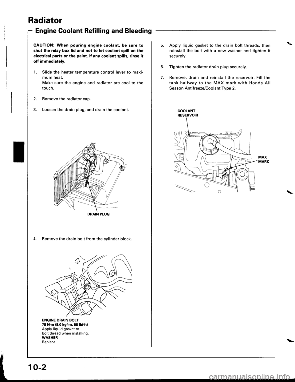
3. Loosen the drain plug, and drain the coolant.
4. Remove the drain bolt from the cylinder block.
ENGINE DRAIN BOLT78 N.m (8.0 kgf.m,58 lbf.ftlApply liquid gasket tobolt thread when installing.WASHERReolace.
DRAIN PIUG
I \.--
\_-l - I
\
6.
7.
5. Apply liquid gasket to the drain bolt threads, then
reinstall the bolt with a new washer and tighten it
securely.
Tighten the radiator drain plug securely.
Remove, drain and reinstall the reservoir. Fill the
tank halfway to the MAX mark with Honda All
Season Antifreeze/Coolant Type 2.
COOLANTRESERVOIR
tW.
\-