throttle valve HONDA INTEGRA 1998 4.G Workshop Manual
[x] Cancel search | Manufacturer: HONDA, Model Year: 1998, Model line: INTEGRA, Model: HONDA INTEGRA 1998 4.GPages: 1681, PDF Size: 54.22 MB
Page 58 of 1681
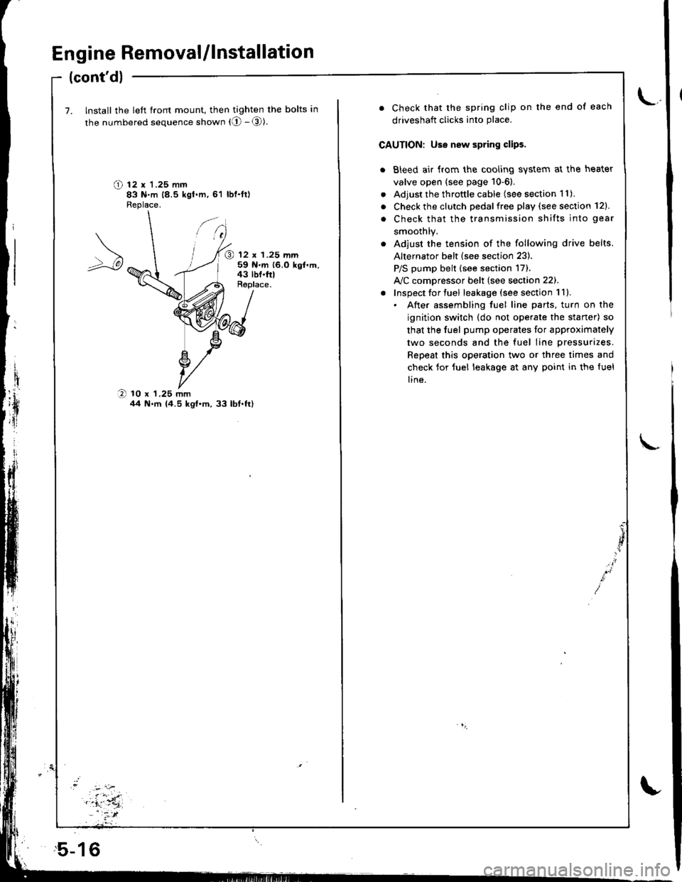
Engine Removal/lnstallation
{cont'dl
7. Install the left front mount, then tighten the bolts in
the numbered sequence shown (O - @).
O t2 x '1.25 mm83 N.m 18.5 kgt.m,61 lbl.ft)Fleplace.
@ 12 x 1.25 mm59 N.m 16.0 kgf.m,43 lbf.frlReplace.
O 10 x 1.25 mmil4 N.m 14.5 kgt'm,33 lbt.ft)
,5-16
. Check that the spring clip on the end of each
driveshaft clicks into place.
CAUTION: Use new spring clips.
. Bleed air {rom the cooling system at the heater
valve open (see page 10-6).
. Adjust the throttle cable (see section 1 1).
. Check the clutch pedalfree play (see section 12).
. Check that the transmission shifts into gear
smoothlY.
. Adjust the tension of the following drive belts.
Alternator belt {see section 23).
P/S pump belt (see section 171.
A/C comDressor belt (see section 22).
! Inspect for tuel leakage (see section 1ll.. After assembling fuel line parts, turn on the
ignition switch (do not operate the staner) so
that the fuel pump operates for approximately
two seconds and the fuel line pressurizes.
Repeat this operation two or three times and
check for tuel leakage at any point in the {uel
line.
Page 80 of 1681
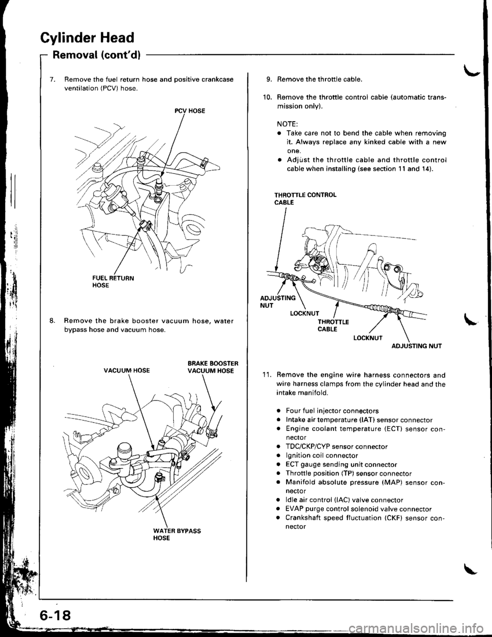
Gylinder Head
Removal (cont'dl
Remove the fuel return hose and positive crankcase
ventilation (PCV) hose.
Remove the brake booster vacuum hose, water
bypass hose and vacuum hose.
ltosE
VACUUM HOSE
6-18
10.
9.
11.
Remove the throttle cable,
Remove the throttle control cable (automatic trans-
mission only).
NOTE:
. Take care not to bend the cable when removing
it. Always replace any kinked cable with a new
one.
. Adjust the throttle cable and throttle control
cable when installing (s€e section 11 and 14).
THROTTLE CONTROLCABLE
ADJUSTING NUT
Remove the engine wire harness connectors and
wire harness clamps f.om the cylinder head and the
intake manifold.
Four fuel injector connectors
Intake air temperature (lATl sensor connector
Engine coolant temperature {ECT) sensor con,
nector
TDC/CKP/CYP sensor connector
lgnition coil connector
ECT gauge sending unit connector
Throttle position (TP) sensor connector
Manifold absolute pressure (MAP) sensor con-
necto r
ldle air control (lAC) valve connector
EVAP purge control solenoid valve connector
Crankshaft speed fluctuation (CKF) sensor con-
nector
a
a
a
a
a
a
a
a
ADJUSTING
Page 187 of 1681
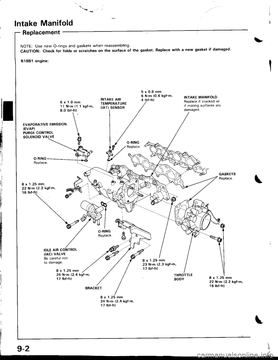
lntake Manifold
Replacement
PURGE CONTROLSOLENOIO VALVE
8 x 1.25 mm22 N.m 12.2 kgl'm'
16
IDLE AIR
\
NOTE: Use new O-rings and gaskets when reassembling
CAUTION: Check tor tolds or scratches on the sudace of the gasket.
81881 engine:
Replace with a new gasket if damaged.
&
d
ll
,ii
ilnl
iii
I
I
ii
il
lli
fr
EVAPORATIVE EMISSION(EVAP}
11 N.m l'1.1 kg{.m,8.0 rbf.fr)
INTAKE AIRTEMPERATURE(IAT} SENSOB
5xO.8mm6 N.m 10.6 kgf'm,4 tbI.tt)
8 x 1.25 mm23 N.m (2.3 kgt'm,17 tbf.fl)
INTAKE MANIFOLOReplace if cracked orif mating surfaces areoamageo.
lrAcl vALvEBe careful not
to damage,
8 x 1.25 mm24 N.m 12.4 kqf .m,
17 lbI.Ir)THROTTLEBODY8 x 1.25 mm22 N.rn 12.2 kgl.m,16 tbf.frl
24 N.m {2.4 kgt.m,17 tbf.{r)
\I
.lll
BRACKET
Page 188 of 1681
.'.,.'.attj
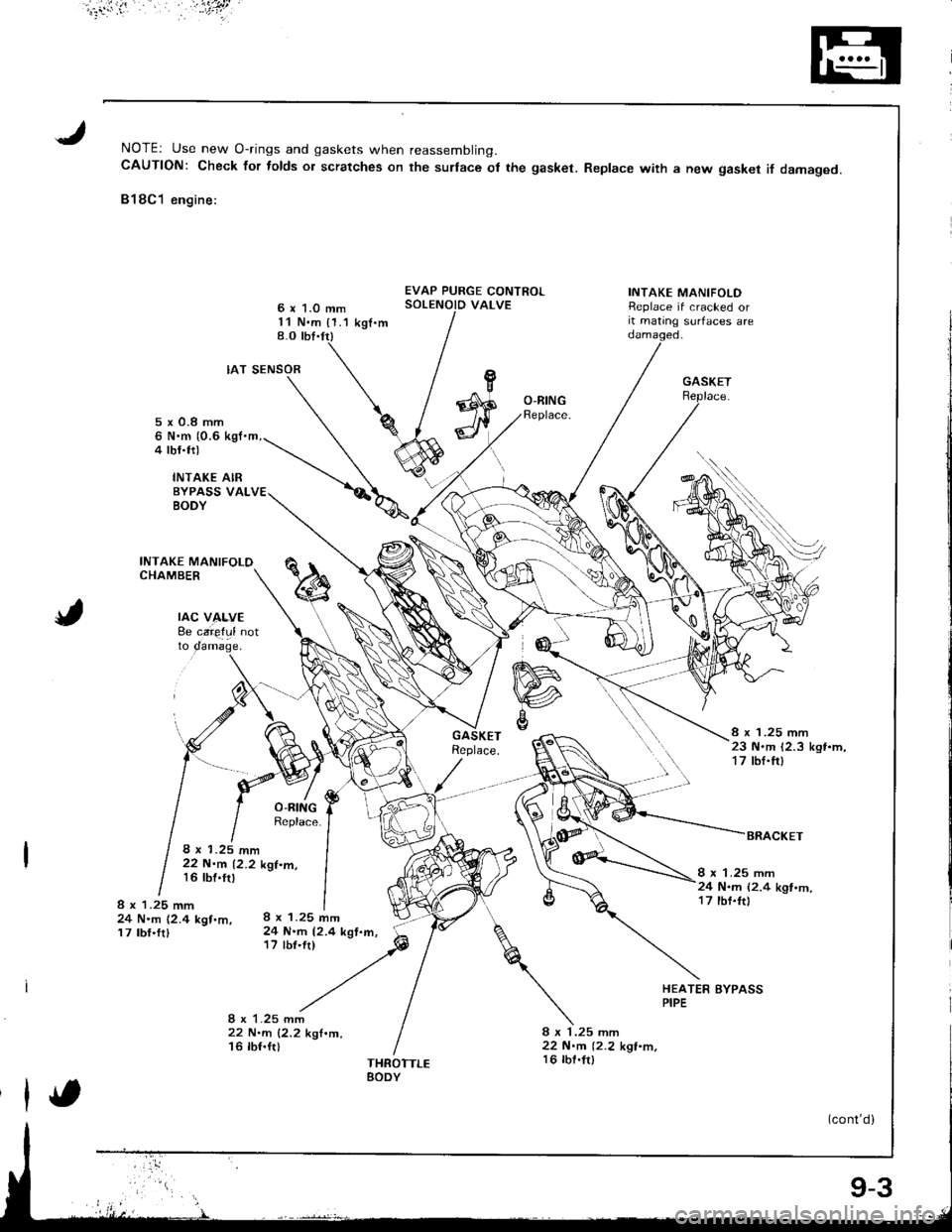
NOTEr Use new O-rings and gaskets when reassembling.CAUTION: Check for folds or scratches on the surlace ot the gasket. Replace with a new gasket if damaged.
818C1 engine:
6 x 1.0 mm11 N.m {1.1 kgt.m8.O tbt.trl
EVAP PURGE CONTROLSOLENOID VALVEINTAKE MANIFOLDReplace if cracked orit mating surfaces are
rAc v4f,vE8e caie{ul notto
IAT SENSOR
8 x 1.25 mm24 N.m 12.4 kgt.m,17 tbf'fr)
22 N.m 12.2 k'l.m,16 lbf.ftl
O-BINGReplace.5x0.8mm6 N.m (0.6 kgI'm,4 tbf.trl
INTAKE AIRBYPASS VALBODY
INTAKE MANIFOLOCHAMBER
8 x 1.25 mm23 N.m 12.3 kgt.m,17 tbf.ft)
8 x 1.25 mm22 N.m 12.2 kgt.m,16 tbt'tr)I x 1.25 mm24 N.m (2.4 kgl.m,17 tbf.ft)8 x 1.25 mm24 N.m (2.4 kgt.m,17 tbf.frl
HEATER BYPASSPIPE
8 x 1.25 mm22 N.m 12.2 kgt.m,16 lbt.fr)THROTTLEEODY
(cont'd)
9-3
Page 189 of 1681
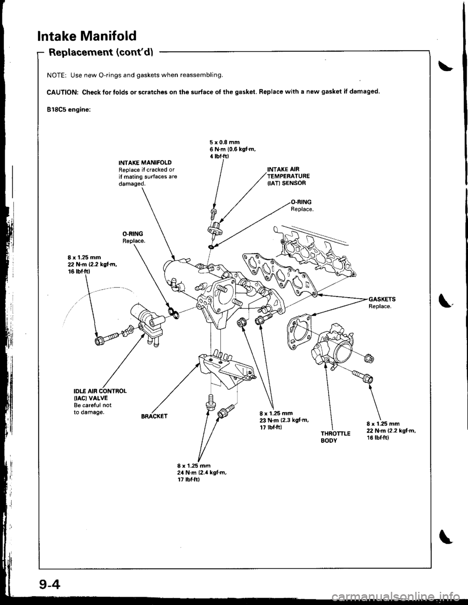
Intake Manifold
Replacement (con(d)
NOTE: Use new O-rings and gaskets when reassembling.
CAUTION: Check for tolds or scratches on the surface oI the gasket. Replace with a new gasket if damaged
818C5 engine:
5x0,8mm6 N.m 10.6 kgl m,
INTAKE MANIFOLDRoplace il cracked oril mating surfaces aredamaged.
I x 1.25 mm212 N.n 12.2 tsl'm,16 tbf.ftl
\.
IDI.f AIR CONTROL(IACI VALVEBe careful notto dsmage.8 x 1.25 mmZ' N.m 12.3 kgt'm,17 tbl.ft)THROTTLEBODY
8 x 1.25 mm22 N.m 12.2 kgtm,16 tbf ft)
8 x'1.25 mm24 N.m l2.il kgf.m,17 rbt.ft)
9-4
Page 208 of 1681
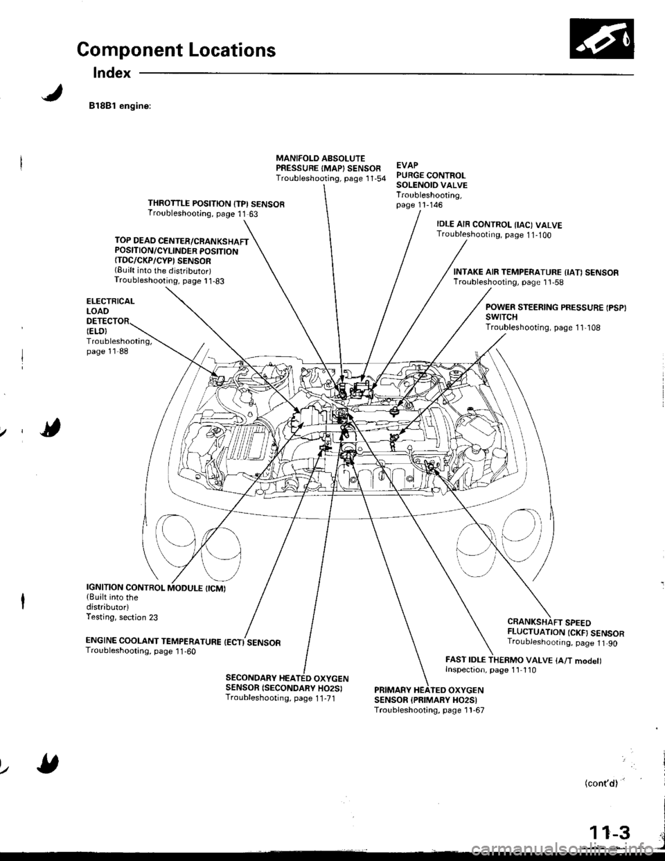
Component Locations
Index
81881 engine:
TOP DEAD CENTER/CRANKSHAFTPOSITION/CYLINDER POSITION{TDC/CKP/CYP' SENSOR(Built into the distributor)Troubleshooting, page I 1-83
ELECTRICALLOAO
Troubleshooting,page 11-88
MANIFOLD AsSOLUTEPRESSURE IMAP} SENSOFTroubleshooting, psge 1 '1,54EVAPPURGE CONTROLSOLENOID VALVETroubleshooting,page 11-146THROTTLE POSITION {TPI SENSORTroubleshooting, page 11 63
IELO}
IDLE AIR CONTROL IIAC) VALVETroubleshooting, page 1 1-1OO
CRANKSHAFT SPEEDFLUCTUATION {CKF} SENSORTroubJeshoonng. page 1t 90
FAST IDLE THERMO VALVE {A/T modet)Inspection, page 1'l 110
INTAKE AIR TEMPERATURE {IA1 SENSORTroubleshooting, page 1 'l -58
POWER STEERING PRESSURE IPSP}swtTcHTroubleshooting, page 1 1,108
IGNITION CONTROL{Built into thedistributorlTesting, section 23
ENGTNE cooLANT TEnapenerune {ectisensoaTroubleshooting, page 1 1 -60
SECONDARY HEATED OXYGENSENSOR (SECONDARY HO2SITroubleshooting, page 1 1-71PRIMARY HEATEO OXYGENSENSOR {PFIMARY HO2SITroubleshooting, page 1 1-67
lz
(cont'd)'
Page 209 of 1681
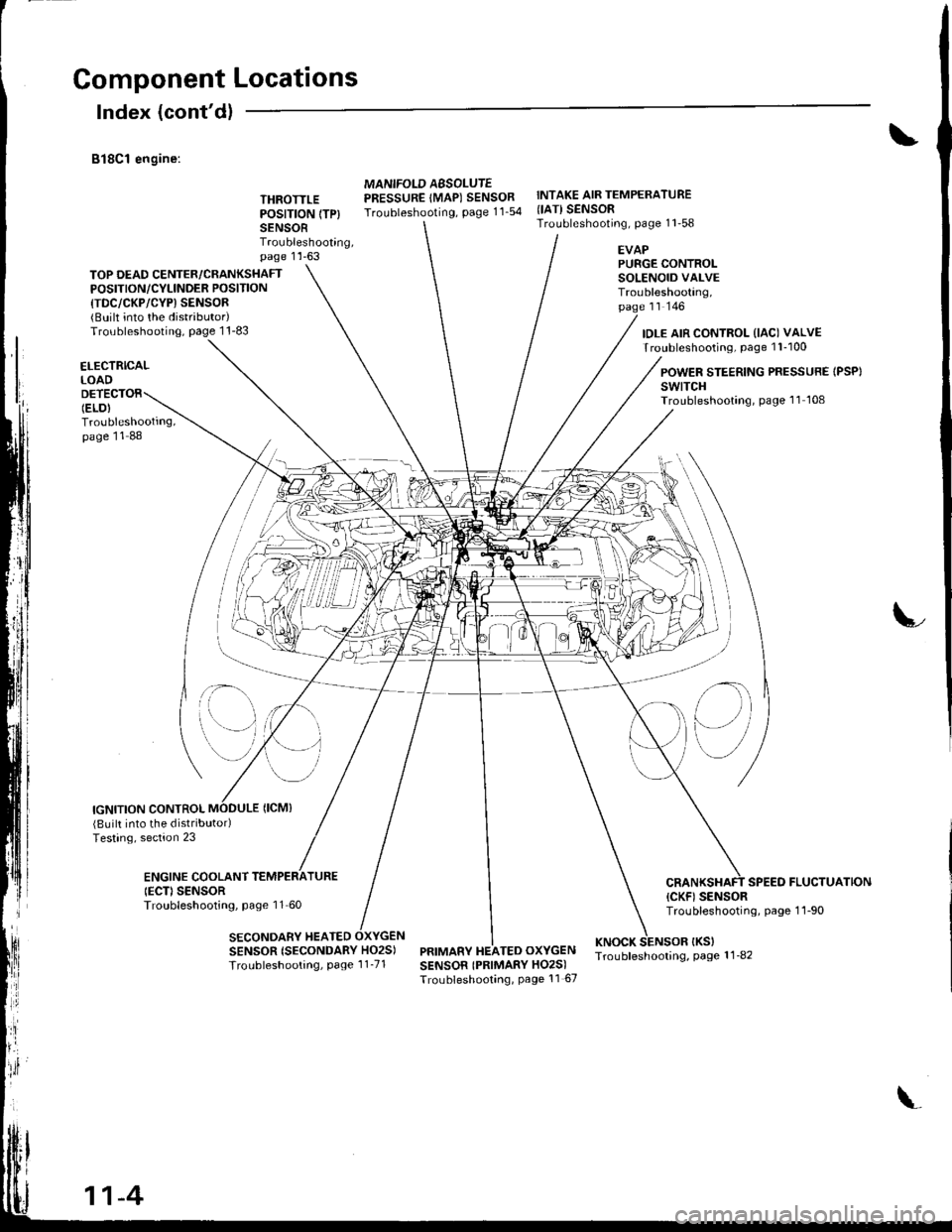
Component Locations
Index (cont'dl
B18C1 engine:
THROTTLEPOSITION (TP}
SENSORTroubleshooting,page 1 'l -63
MANIFOLD AESOLUTEPRESSURE IMAP) SENSORTroubleshooting, page 11_54
INTAKE AIR TEMPERATURE{IATI SENSORTroubleshooting, page 11'58
TOP DEAD CENTER/CRANKSHAFTPOSITION/CYLINOER POSITION
{TDC/CKP/CYP) SENSOR{BUilt into the distributor)Troubleshooting, page 1 1-83
EVAPPURGE CONTROLSOLENOID VALVETroubleshooting,page rr rqo
IDLE AIR CONTROL (IAC) VALVETroubleshooting, page 1 l-100
ELECTRICALLOAD
Troubleshooting,page 11 88
POWER STEERING PRESSURE IPSP}swtTcHTroubleshooting, page 'l1 108
IGNITION CONTROL
;- \
SENSOR {SECONDARY HO2S)
Troubleshooting, Page 1 1_71
(Built into the distributodTesting, section 23
ENGINE COOLANTIECD SENSORTroubleshooting, page 11 60
SECONDARY HEATED
SPEED FLUCTUATION(CKF) SENSORTroubleshooting, page 1 1-90
PRIMARY HEATED OXYGENKNOCK SENSOR IKSITroubleshooling, page 1 1_82SENSOR IPRIMARY HO2S)Troubleshooting, Page 11 67
il\
e)
11-4
Page 210 of 1681
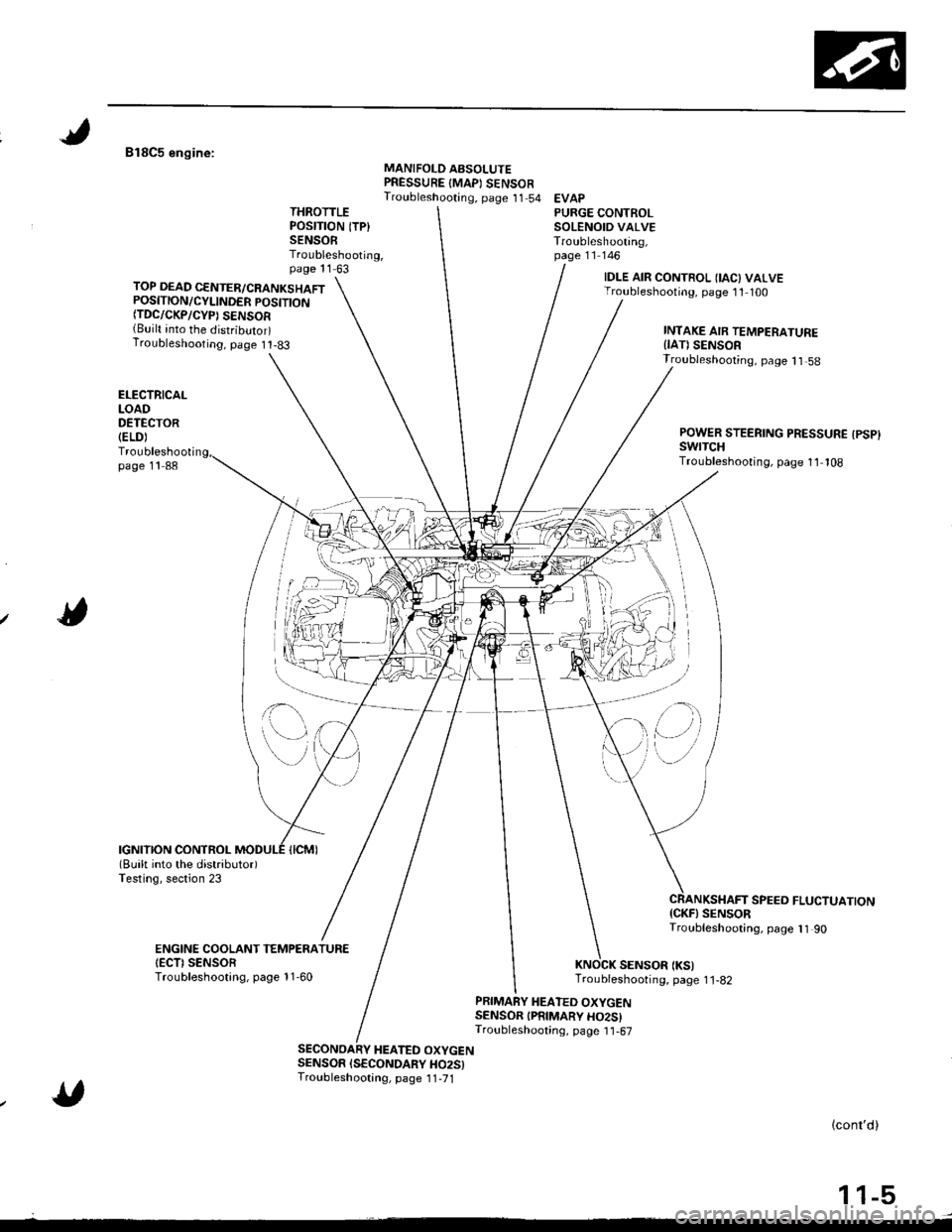
818C5 engine:MANIFOLD ABSOLUTEPRESSURE {MAPI SENSOFTroubleshooting, page 11 54 EVAPTHROTTLEPOSITION ITP}SENSORTroubleshooting,page 11 63
PURGE CONTROLSOLENOID VALVETroubleshooting,page 11 146
TOP DEAD CENTER/CRANKSHAFTPOSITION/CYLINDER POSITTONfiDC/CKP/CYP) SENSOR{Built into the distributor)Troubleshooting, page I t-83
IDLE AIR CONTROL IIAC) VALVETroubleshooting, page 11 100
INTAKE AIR TEMPERATUREIIAT) SENSOR
ELECTRICALLOADDETECTOR(ELD)
Troubleshootipage 11 88
Troubleshooting, page 1 1,58
POWER STEERING PRESSURE {PSP}swrTcHTroubleshooting, page 11 108
SPEEO FLUCTUATION{CKF} SENSORTroubleshooting, page 11 90
SENSOR (KS)Troubleshooting, page 1 1-82
ENGINE COOLANT TEMPENATUR€IECTI SENSORTroubleshootang, page 11-60
PRIMARY HEATED OXYGENSENSOR IPRIMARY HO2SITroubleshooting, page I1-67
HEATED OXYGENSENSOR ISECONDARY HO25)Troubleshootang, page 1 1,71
lcont'd)
1 1-5
,'(l)
Page 211 of 1681
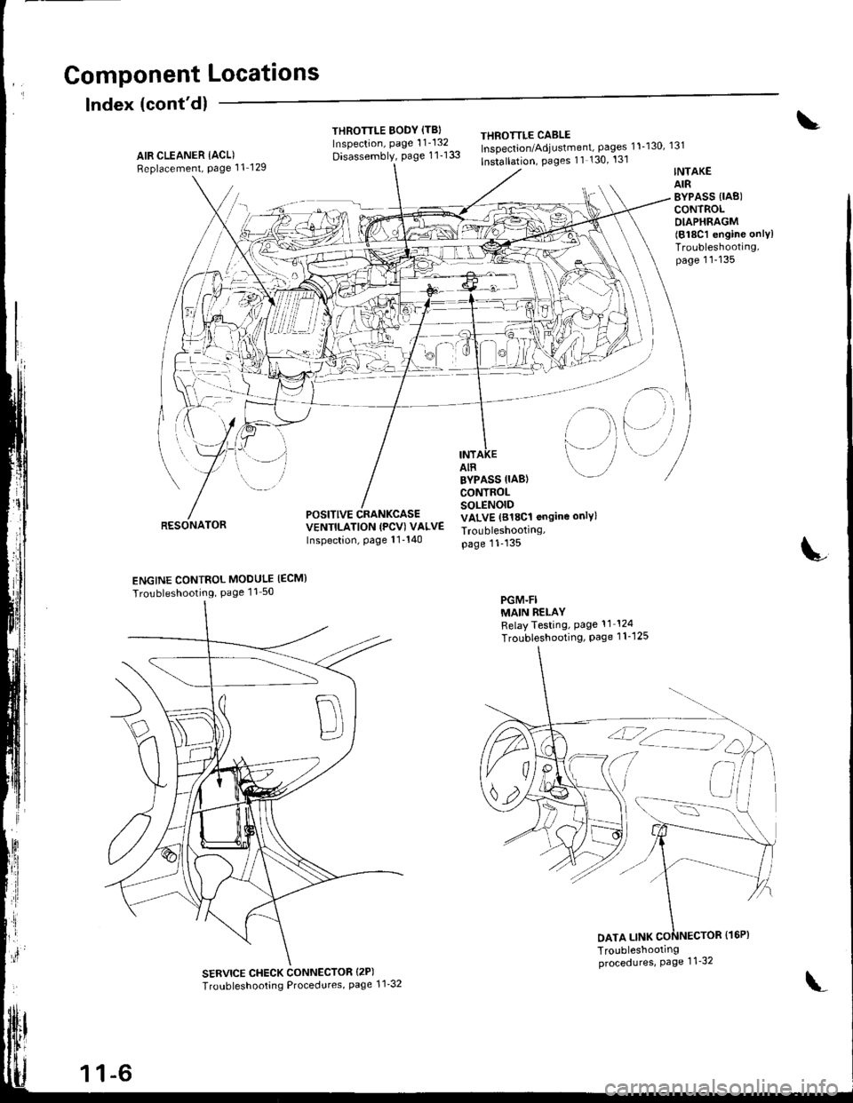
Gomponent Locations
Index (cont'dl
THROTTLE BODY {TBIInspection, page 1 1'132
Disassembly, page 1 1-133
THEOTTLE CABLEInspection/Adjustment, pages 11-130, 131
lnstallation, Pages 11 130' 131AIR CLEANER IACL)Replacement, Page 11 129
RESONATOR
INTAKEAIRBYPASS {IAB)CONTROLDIAPHRAGM(818C1 engine onlylTroubleshooting,page 11-135
i-)
i--- / /
i rl
l'-' i
INTAIR
POSITIVE CRANKCASEVENTILATION (PCV) VALVEInspection, page 11'140
BYPASS IIAB}CONTROLSOLENOIDVALVE (818C1 ongine only)
Troubleshootrng,page 11-135
PGM-FIMAIN RELAYRelayTesting, Page 11 124
Troubleshooting, Page 1 1-1 25
L
ENGINE CONTROL MODULE IECM}
Tro!bleshooting, Page 11 50
SERVICE CHECK CONNECTOR {2P)
Troubleshooting Procedures, page 1 1'32
DATA LINK
1 1-6
\'
Page 241 of 1681
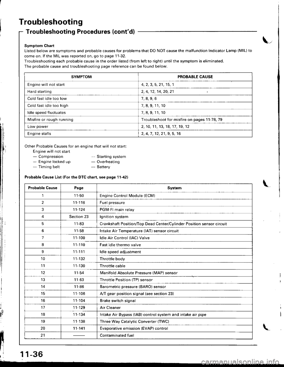
Troubleshooting
Troubleshooting Procedures (cont'd)
Symptom Chart
Listed below are symptoms and probable causes for problems that DO NOT cause the malfunction Indicator Lamp (MlL) to
come on. lf the MIL was reported on, go to page 11-32.
Troubleshooting each probable cause in the order listed (from left to right) until the symptom is eliminated.
The probable cause and troubleshooting page relerence can be found below.
Other Probable Causes for an engine that will not start:
Engine will not sta rt- Compression- Engine locked up- Timing belt
\_
- Starting system- Overheating- Battery
'4,
It
Probable Cause List (For the DTC chart. see page 11-421
Probable CausePageSystem
111-50Engine Control Module (ECM)
211118Fuel pressure
311-124PGM-Fl main relay
4Section 23lgnition system
51 1-83Crankshaft Position/ToD Dead Center/Cylinder Position sensor circuit
11-58Intake Air Temperature (lAT) sensor circuit
71 '�t- 100ldle Air Control (lAC) Valve
811110Fast idle thermo valve
I11lllldle speed adjustment
'1011-132Throttle body
111 1-130Throttle cable
1211-54lvlanifold Absolute Pressure {MAP) sensor
IJ1163Throttle Position {TP) sensor
1411-86Barometric pressure (BARO) sensor
1 '1 106A/T gear position signal {see section 23)
16'1 1 104Brake switch signal
1711 129Air Cleaner
181 1- 134Intake Air Bypass {lAB} control system and intake air pipe
19'1 1 138Three Way Catalytic Convener (TWC)
2011-141Evaporative emission (EVAP) control
21Contaminated fuelll ll 21 | - | cont"-in"t"o tu"
11 l-
I
,l 11-36
-
SYMPTOMPROBABLE CAUSE
Engine will not stan4, 2, 3,5, 21, 15, 1
Hard starting2, 4, 12, 14,20,21
Cold fast idle too low
Cold fast idle too high7, 8, 9, 11, r0
ldle speed fluctuates7,8,9,11,10
Misfire or rough runningTroubleshoot for misfire on pages 11-78,79
Low power2, 10,'t1, 13, 14, 17, 19, 12
Engine stalls2, 4,1 , 12,21,9, 5, 16