Hyundai Accent 2006 Owner's Manual
Manufacturer: HYUNDAI, Model Year: 2006, Model line: Accent, Model: Hyundai Accent 2006Pages: 599, PDF Size: 17.59 MB
Page 251 of 599
6
DO-IT-YOURSELF MAINTENANCE
33REMOVAL OF WATER FROM THE FUEL FILTER
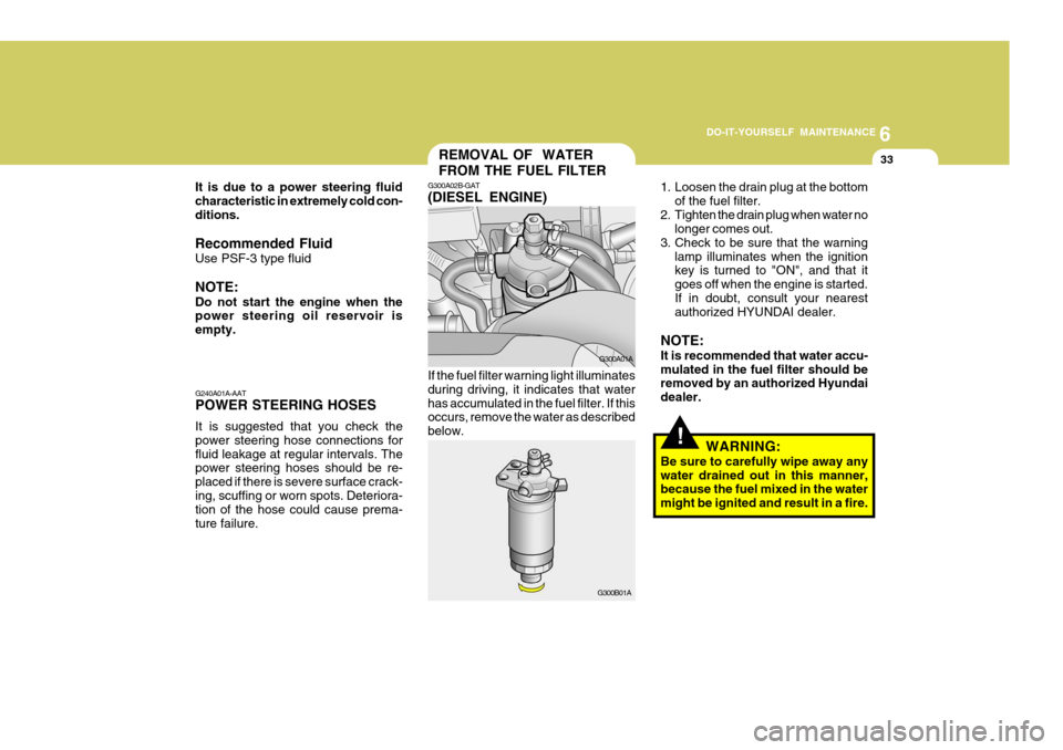
1. Loosen the drain plug at the bottom
of the fuel filter.
2. Tighten the drain plug when water no longer comes out.
3. Check to be sure that the warning
lamp illuminates when the ignition key is turned to "ON", and that it goes off when the engine is started.If in doubt, consult your nearest authorized HYUNDAI dealer.
NOTE: It is recommended that water accu- mulated in the fuel filter should be removed by an authorized Hyundai dealer.
G300B01A G300A01A
G240A01A-AAT POWER STEERING HOSES It is suggested that you check the power steering hose connections forfluid leakage at regular intervals. The power steering hoses should be re- placed if there is severe surface crack-ing, scuffing or worn spots. Deteriora- tion of the hose could cause prema- ture failure. G300A02B-GAT (DIESEL ENGINE) If the fuel filter warning light illuminates during driving, it indicates that waterhas accumulated in the fuel filter. If this occurs, remove the water as described below.
It is due to a power steering fluidcharacteristic in extremely cold con-ditions. Recommended Fluid Use PSF-3 type fluid NOTE: Do not start the engine when the power steering oil reservoir is empty.
!WARNING:
Be sure to carefully wipe away any water drained out in this manner, because the fuel mixed in the water might be ignited and result in a fire.
Page 252 of 599
6 DO-IT-YOURSELF MAINTENANCE
34HEADLIGHT AIMING ADJUSTMENT
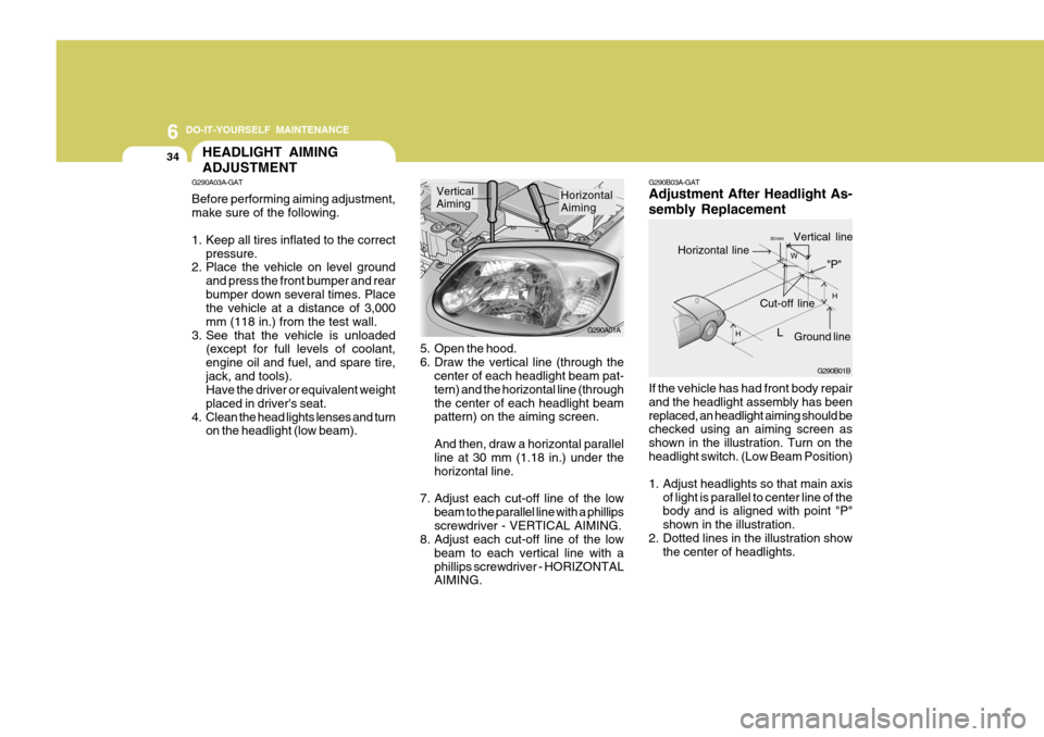
5. Open the hood.
6. Draw the vertical line (through the
center of each headlight beam pat-tern) and the horizontal line (throughthe center of each headlight beam pattern) on the aiming screen. And then, draw a horizontal parallel line at 30 mm (1.18 in.) under the horizontal line.
7. Adjust each cut-off line of the low beam to the parallel line with a phillipsscrewdriver - VERTICAL AIMING.
8. Adjust each cut-off line of the low
beam to each vertical line with aphillips screwdriver - HORIZONTAL AIMING. G290A01A
Horizontal Aiming
Vertical Aiming
If the vehicle has had front body repair and the headlight assembly has beenreplaced, an headlight aiming should be checked using an aiming screen as shown in the illustration. Turn on theheadlight switch. (Low Beam Position)
1. Adjust headlights so that main axisof light is parallel to center line of the body and is aligned with point "P" shown in the illustration.
2. Dotted lines in the illustration show the center of headlights.
G290B03A-GAT Adjustment After Headlight As- sembly Replacement
G290A03A-GAT Before performing aiming adjustment, make sure of the following.
1. Keep all tires inflated to the correct
pressure.
2. Place the vehicle on level ground
and press the front bumper and rear bumper down several times. Place the vehicle at a distance of 3,000 mm (118 in.) from the test wall.
3. See that the vehicle is unloaded (except for full levels of coolant,engine oil and fuel, and spare tire,jack, and tools). Have the driver or equivalent weight placed in driver's seat.
4. Clean the head lights lenses and turn on the headlight (low beam). G290B01B
LW
H
H Cut-off line
Ground line
"P"
Horizontal line
Vertical line30 mm
Page 253 of 599
6
DO-IT-YOURSELF MAINTENANCE
35REPLACEMENT OF LIGHT BULBS
HLC5033
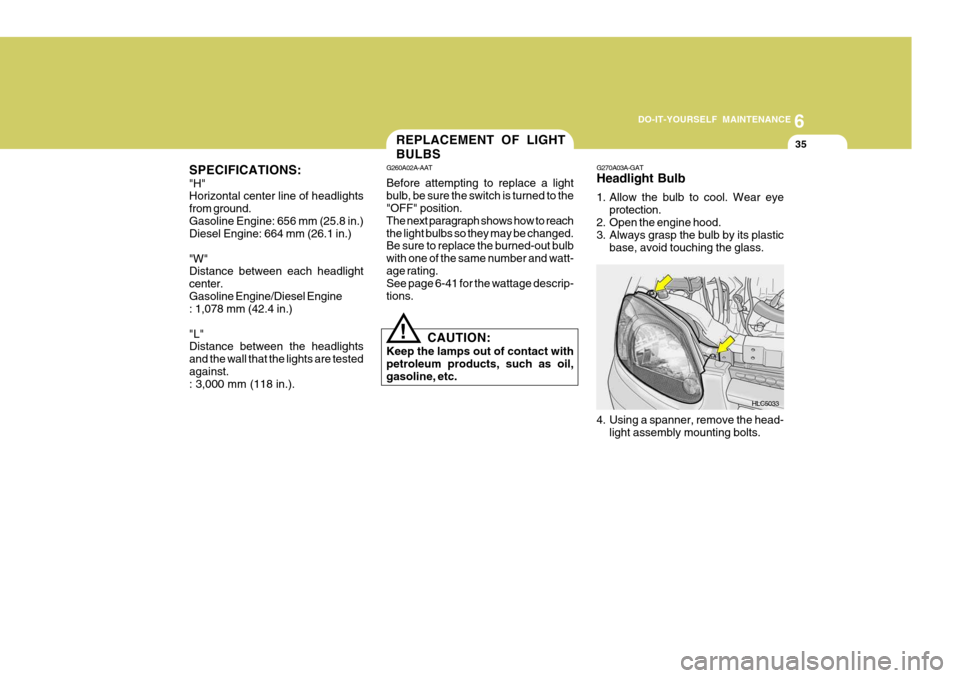
G270A03A-GAT Headlight Bulb
1. Allow the bulb to cool. Wear eye
protection.
2. Open the engine hood.
3. Always grasp the bulb by its plastic
base, avoid touching the glass.
SPECIFICATIONS: "H" Horizontal center line of headlights from ground.Gasoline Engine: 656 mm (25.8 in.) Diesel Engine: 664 mm (26.1 in.) "W" Distance between each headlight center.Gasoline Engine/Diesel Engine : 1,078 mm (42.4 in.) "L" Distance between the headlights and the wall that the lights are testedagainst. : 3,000 mm (118 in.). G260A02A-AAT Before attempting to replace a light bulb, be sure the switch is turned to the "OFF" position. The next paragraph shows how to reachthe light bulbs so they may be changed. Be sure to replace the burned-out bulb with one of the same number and watt-age rating. See page 6-41 for the wattage descrip- tions.
CAUTION:
Keep the lamps out of contact with petroleum products, such as oil, gasoline, etc.
!
4. Using a spanner, remove the head-light assembly mounting bolts.
Page 254 of 599
6 DO-IT-YOURSELF MAINTENANCE
36
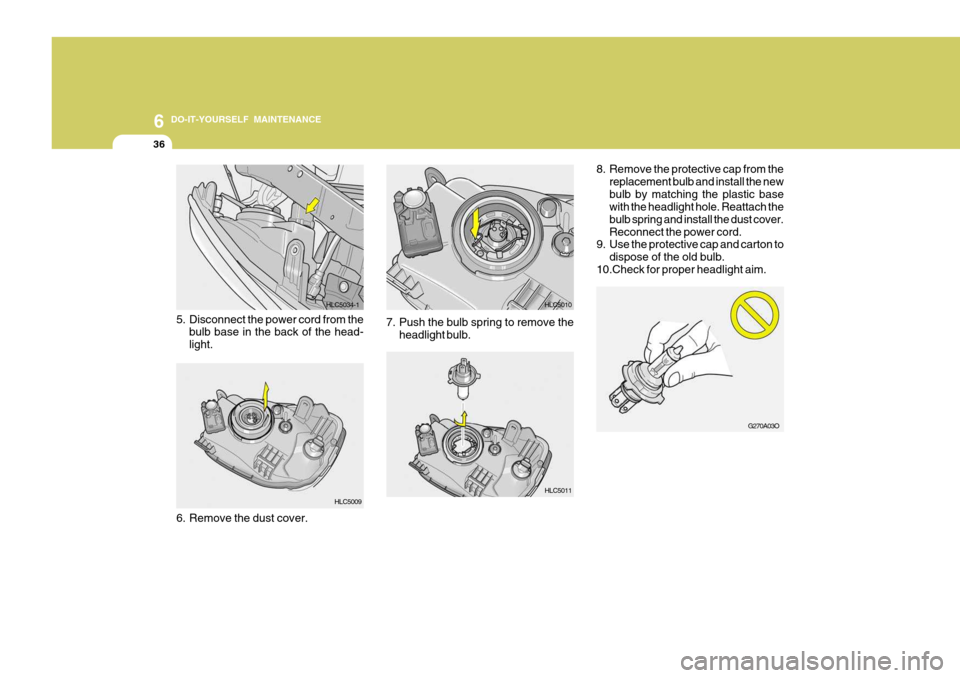
8. Remove the protective cap from the
replacement bulb and install the new bulb by matching the plastic base with the headlight hole. Reattach the bulb spring and install the dust cover.Reconnect the power cord.
9. Use the protective cap and carton to
dispose of the old bulb.
10.Check for proper headlight aim.
6. Remove the dust cover. HLC5011
HLC5009
HLC5034-1
5. Disconnect the power cord from the bulb base in the back of the head-light. 7. Push the bulb spring to remove the
headlight bulb. HLC5010
G270A03O
Page 255 of 599
6
DO-IT-YOURSELF MAINTENANCE
37
!
G270D01A-GAT Rear Combination Light
G270D01A
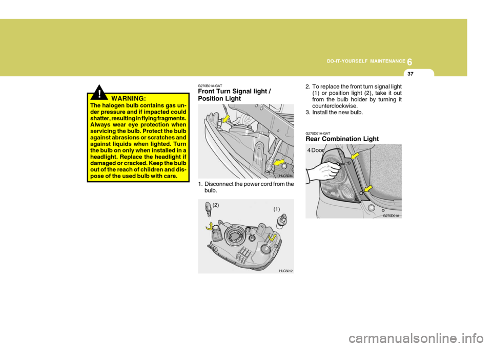
G270B01A-GAT Front Turn Signal light / Position Light
1. Disconnect the power cord from the
bulb. HLC5034 HLC50122. To replace the front turn signal light
(1) or position light (2), take it out from the bulb holder by turning it counterclockwise.
3. Install the new bulb.
4 Door
(1)
(2)
WARNING:
The halogen bulb contains gas un- der pressure and if impacted couldshatter, resulting in flying fragments. Always wear eye protection when servicing the bulb. Protect the bulbagainst abrasions or scratches and against liquids when lighted. Turn the bulb on only when installed in aheadlight. Replace the headlight if damaged or cracked. Keep the bulb out of the reach of children and dis- pose of the used bulb with care.
Page 256 of 599
6 DO-IT-YOURSELF MAINTENANCE
38
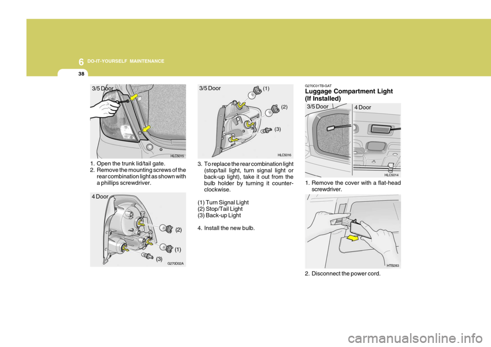
1. Open the trunk lid/tail gate.
2. Remove the mounting screws of the
rear combination light as shown witha phillips screwdriver. 3. To replace the rear combination light
(stop/tail light, turn signal light or back-up light), take it out from the bulb holder by turning it counter- clockwise.
(1) Turn Signal Light(2) Stop/Tail Light (3) Back-up Light
4. Install the new bulb. (1)
(2)
(3) G270C01TB-GAT Luggage Compartment Light (If Installed)
HLC5014
1. Remove the cover with a flat-head screwdriver.
2. Disconnect the power cord. HTB283
3/5 Door
4 Door
HLC5015
G270D02A HLC5016
4 Door 3/5 Door
(2)
(1)
(3) 3/5 Door
Page 257 of 599
6
DO-IT-YOURSELF MAINTENANCE
39
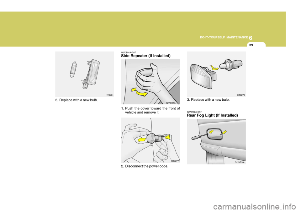
G270F02A-GAT Rear Fog Light (If Installed)
G270F01AHTB278
3. Replace with a new bulb.
HTB277
G270E01A-GATSide Repeater (If Installed)
G270E01A
1. Push the cover toward the front of vehicle and remove it.
2. Disconnect the power code.
3. Replace with a new bulb.
HTB284
Page 258 of 599
6 DO-IT-YOURSELF MAINTENANCE
40
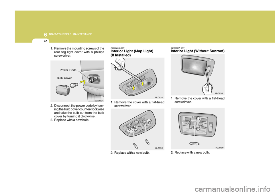
G270G01A-GAT Interior Light (Map Light) (If Installed)
1. Remove the mounting screws of the
rear fog light cover with a phillips screwdriver.
2. Disconnect the power code by turn- ing the bulb cover counterclockwiseand take the bulb out from the bulb cover by turning it clockwise.
3. Replace with a new bulb. G270F02A
1. Remove the cover with a flat-head
screwdriver.
2. Replace with a new bulb. HLC5017 HLC5018G270H01A-GAT Interior Light (Without Sunroof)
1. Remove the cover with a flat-head
screwdriver. HLC5019
HLC5020
2. Replace with a new bulb.
Bulb Cover Power Code
Page 259 of 599
6
DO-IT-YOURSELF MAINTENANCE
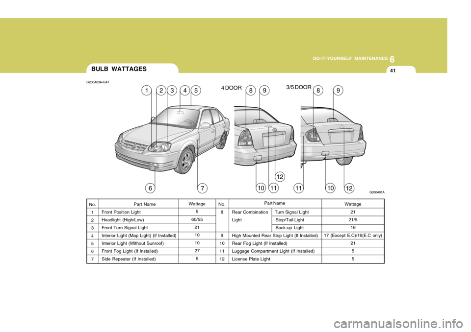
41BULB WATTAGES
Rear Combination Turn Signal Light
Light Stop/Tail Light
Back-up Light
High Mounted Rear Stop Light (If Installed)Rear Fog Light (If Installed) Luggage Compartment Light (If Installed)License Plate Light
Part Name
Front Position LightHeadlight (High/Low) Front Turn Signal Light Interior Light (Map Light) (If Installed)Interior Light (Without Sunroof) Front Fog Light (If Installed) Side Repeater (If Installed) No.
8 9
10 11 12
G280A03A-GAT
G280A01A
52
Wattage5
60/55 21 10 1027
5No. 1
2 34 5 67Wattage
21
21/5 16
17 (Except E.C)/16(E.C only) 215 5
Part Name
76121011
1349898
1011
12
4 DOOR
3/5 DOOR
Page 260 of 599

6 DO-IT-YOURSELF MAINTENANCE
42
G200C02A-GAT Engine Compartment (Gasoline Engine)
HLC5027
NOTE:
Not all fuse panel descriptions in this manual may be applicable to your vehicle. It is accurate at the time of printing.
When you inspect the fuse box on your vehicle, refer to the fuse box label.FUSE RATING 120A50A 50A20A30A20A 30A 30A30A30A20A 10A 10A 10A 10A10A 10A10A15A 10A15A 15A 10A 25A PROTECTED COMPONENTS
Charging (Generator) Fuse 6, 7, 8, 9, Horn fuse, Room lamp fuse
Head lamp fuse, Front fog lamp fuse, Tail lamp relay, H/LP washer fuse
Engine control relay, Generator, Fuel pump relay, ECU #3 fuse Ignition power source, Start relayRadiator fan control Blower control ABS control, ABS bleeding connectorABS control, ABS bleeding connector Power window Condenser fan controlRadiator fan, Condenser fan, ECM, Oxygen sensor, Purge control valve,
SMATRA, Glow plug relay, Heater relay, Stop lamp switch A/C relayHorn relay Illumination lamps, Left rear combination lamp, License lamp, DRL control, Position lamp, H/LP washer relayRight rear combination lamp, License lamp, Position lamp Left head lamp, DRL control, Instrument cluster Right head lampFront fog lamp relay
Instrument cluster, Courtesy lamp, Trunk room lamp, ETACM, DLC, Door warning, Multipurpose check connectorAudio, Digital clock, Power antenna, A/C switch, Rear fog lamp switch Idle speed actuator, ECM, Camshaft position sensor, EGR actuator, Throttle plate actuatorECM Head lamp washer motor
Fuel pump relay, Fuel pump motor
ALT
BATTERY LAMPECU
IGN
RAD FAN
BLOWER
ABS ABS
P/WDW
COND FAN
ECU #1
A/CON COMP HORN
TAIL LH
TAIL RH
H/LP LH
H/LP RH
FRONT FOG
ROOM LP AUDIO
ECU #2 ECU#3
H/L WASHER
FUSIBLE
LINK
FUSE
DESCRIPTION
F/PUMP CHK (E50)
FUSE PANEL DESCRIPTION