clock Hyundai Elantra 2009 Инструкция по эксплуатации (in Russian)
[x] Cancel search | Manufacturer: HYUNDAI, Model Year: 2009, Model line: Elantra, Model: Hyundai Elantra 2009Pages: 308, PDF Size: 15.03 MB
Page 216 of 308
What to do in an emergency
8
6
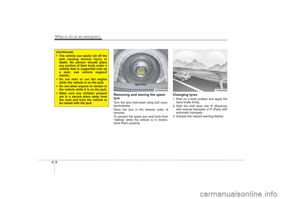
Removing and storing the spare tyre
Turn the tyre hold-down wing bolt coun-
terclockwise.
Store the tyre in the reverse order of
removal.
To prevent the spare tyre and tools from
“rattling” while the vehicle is in motion,
store them properly. Changing tyres
1. Park on a level surface and apply the
hand brake firmly.
2. Shift the shift lever into R (Reverse) with manual transaxle or P (Park) with
automatic transaxle.
3. Activate the hazard warning flasher.
OHD066003
(Continued)
The vehicle can easily roll off the jack causing serious injury or
death. No person should place
any portion of their body under a
vehicle that is supported only by
a jack; use vehicle supportstands.
Do not start or run the engine while the vehicle is on the jack.
Do not allow anyone to remain in the vehicle while it is on the jack.
Make sure any children present are in a secure place away from
the road and from the vehicle to
be raised with the jack.
1VQA4022
Page 217 of 308
69
What to do in an emergency
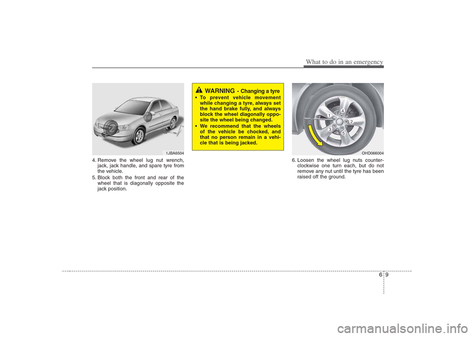
4. Remove the wheel lug nut wrench,jack, jack handle, and spare tyre from
the vehicle.
5. Block both the front and rear of the wheel that is diagonally opposite the
jack position. 6. Loosen the wheel lug nuts counter-
clockwise one turn each, but do not
remove any nut until the tyre has been
raised off the ground.
1JBA6504OHD066004
WARNING - Changing a tyre
To prevent vehicle movement
while changing a tyre, always set
the hand brake fully, and always
block the wheel diagonally oppo-
site the wheel being changed.
We recommend that the wheels of the vehicle be chocked, and
that no person remain in a vehi-
cle that is being jacked.
Page 218 of 308
What to do in an emergency
10
6
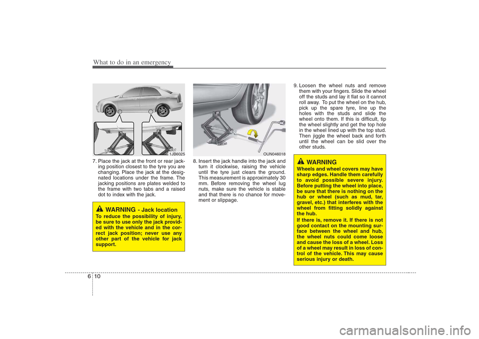
7. Place the jack at the front or rear jack-
ing position closest to the tyre you are
changing. Place the jack at the desig-
nated locations under the frame. The
jacking positions are plates welded to
the frame with two tabs and a raised
dot to index with the jack. 8. Insert the jack handle into the jack and
turn it clockwise, raising the vehicle
until the tyre just clears the ground.
This measurement is approximately 30
mm. Before removing the wheel lug
nuts, make sure the vehicle is stable
and that there is no chance for move-
ment or slippage. 9. Loosen the wheel nuts and remove
them with your fingers. Slide the wheel
off the studs and lay it flat so it cannot
roll away. To put the wheel on the hub,
pick up the spare tyre, line up theholes with the studs and slide the
wheel onto them. If this is difficult, tipthe wheel slightly and get the top holein the wheel lined up with the top stud.
Then jiggle the wheel back and forth
until the wheel can be slid over the
other studs.
WARNING - Jack location
To reduce the possibility of injury,
be sure to use only the jack provid-
ed with the vehicle and in the cor-
rect jack position; never use any
other part of the vehicle for jack
support.
1JB6025OUN046018
WARNING
Wheels and wheel covers may have
sharp edges. Handle them carefully
to avoid possible severe injury.
Before putting the wheel into place,be sure that there is nothing on the
hub or wheel (such as mud, tar,
gravel, etc.) that interferes with the
wheel from fitting solidly againstthe hub.
If there is, remove it. If there is not good contact on the mounting sur-face between the wheel and hub,
the wheel nuts could come loose
and cause the loss of a wheel. Loss
of a wheel may result in loss of con-
trol of the vehicle. This may cause
serious injury or death.
Page 219 of 308
611
What to do in an emergency
10. To reinstall the wheel, hold it on thestuds, put the wheel nuts on the studs and tighten them finger tight.
The nuts should be installed withtheir small diameter ends directed
inward. Jiggle the tyre to be sure it iscompletely seated, then tighten the
nuts as much as possible with yourfingers again.
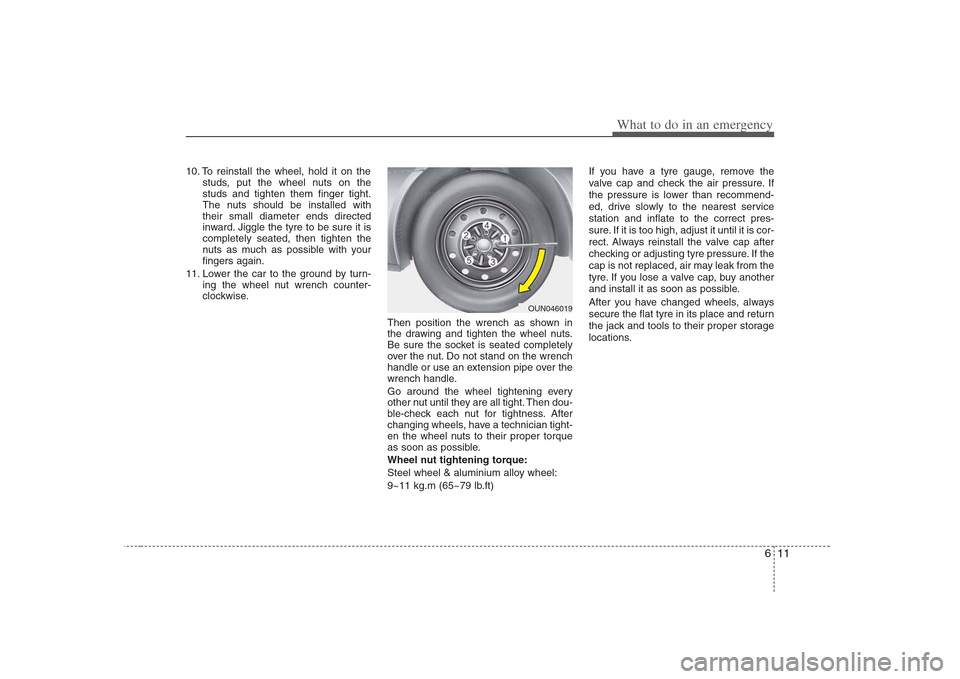
11. Lower the car to the ground by turn- ing the wheel nut wrench counter-
clockwise.
Then position the wrench as shown in
the drawing and tighten the wheel nuts.
Be sure the socket is seated completely
over the nut. Do not stand on the wrench
handle or use an extension pipe over the
wrench handle.
Go around the wheel tightening every
other nut until they are all tight. Then dou-
ble-check each nut for tightness. After
changing wheels, have a technician tight-
en the wheel nuts to their proper torque
as soon as possible.
Wheel nut tightening torque:
Steel wheel & aluminium alloy wheel:
9~11 kg.m (65~79 lb.ft) If you have a tyre gauge, remove the
valve cap and check the air pressure. If
the pressure is lower than recommend-
ed, drive slowly to the nearest servicestation and inflate to the correct pres-
sure. If it is too high, adjust it until it is cor-
rect. Always reinstall the valve cap after
checking or adjusting tyre pressure. If the
cap is not replaced, air may leak from the
tyre. If you lose a valve cap, buy another
and install it as soon as possible.
After you have changed wheels, always
secure the flat tyre in its place and return
the jack and tools to their proper storage
locations.
OUN046019
Page 242 of 308
717
Maintenance
Changing the engine oil and filter
Have engine oil and filter changed by an
authorised Hyundai dealer according tothe Maintenance Schedule at the begin-ning of this section.The high-pressure cooling system has a
reservoir filled with year-round antifreeze
coolant. The reservoir is filled at the fac-
tory.
Check the antifreeze protection and
coolant level at least once a year, at thebeginning of the winter season, and
before traveling to a colder climate.
Checking the coolant level
WARNING
- Removing
radiator cap
Never attempt to remove the radi- ator cap while the engine is oper-
ating or hot. Doing so might leadto cooling system and engine
damage and could result in seri-
ous personal injury from escap-ing hot coolant or steam.
(Continued)
(Continued)
Turn the engine off and wait untilit cools down. Use extreme care
when removing the radiator cap.
Wrap a thick towel around it, and
turn it counterclockwise slowly to
the first stop. Step back while the
pressure is released from the
cooling system. When you aresure all the pressure has been
released, press down on the cap,
using a thick towel, and continue
turning counterclockwise to
remove it.
Even if the engine is not operat- ing, do not remove the radiatorcap or the drain plug while the
engine and radiator are hot. Hot
coolant and steam may still blow
out under pressure, causing seri-
ous injury.
WARNING
Used engine oil may cause irrita- tion or cancer of the skin if left in
contact with the skin for prolonged
periods of time. Used engine oil
contains chemicals that have
caused cancer in laboratory ani-
mals. Always protect your skin by
washing your hands thoroughlywith soap and warm water as soon
as possible after handling used oil.
ENGINE COOLANT
Page 255 of 308
Maintenance
30
7
Battery recharging
Your vehicle has a maintenance-free,
calcium-based battery.
If the battery becomes discharged in a
short time (because, for example, the
headlights or interior lights were left on
while the vehicle was not in use),
recharge it by slow charging (trickle)
for 10 hours.
If the battery gradually discharges because of high electric load while the
vehicle is being used, recharge it at 20-
30A for two hours. Reset items
Items should be reset after the battery
has been discharged or the battery hasbeen disconnected.
Sunroof (See Chapter 4)
Trip computer (See Chapter 4)
Climate control system
(See Chapter 4)
Clock (See Chapter 4)
Audio (See Chapter 4)
Auto up/down window (See chapter 4)(Continued)
When lifting a plastic-cased bat- tery, excessive pressure on the
case may cause battery acid to
leak, resulting in personal injury.
Lift with a battery carrier or with
your hands on opposite corners.
Never attempt to recharge the battery when the battery cablesare connected.
The electrical ignition system works with high voltage. Never
touch these components with theengine running or the ignition
switched on.
Failure to follow the above warn-
ings can result in serious bodily
injury or death.
Page 271 of 308
Maintenance
46
7
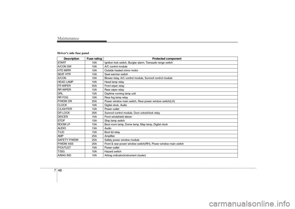
Driver's side fuse panel
Description Fuse rating Protected component
START 10A Ignition lock switch, Burglar alarm, Transaxle range switch
A/CON SW 10A A/C control module
HTD MIRR 10A Outside heated mirror motor
SEAT HTR 15A Seat warmer switch
A/CON 10A Blower relay, A/C control module, Sunroof control module
HEAD LAMP 10A Head lamp relay
FR WIPER 25A Front wiper relay
RR WIPER 15A Rear wiper relay
DRL 15A Daytime running lamp unit
RR FOG 10A Rear fog lamp relay
P/WDW DR 25A Power window main switch, Rear power window switch(LH)
CLOCK 10A Digital clock, Audio
C/LIGHTER 15A Power outlet
DR LOCK 20A Sunroof control module, Door unlock/lock relay
DEICER 15A Front windshield deicer
STOP 15A Stop lamp switch
ROOM LP 15A Boot room lamp, Dome lamp, Map lamp, Digital clock
AUDIO 15A Audio
T/LID 15A Boot lid relay
AMP 25A Amplifier
SAFETY P/WDW 25A Safety power window module
P/WDW ASS 25A Front & rear power window switch(RH), Power window main switch
P/OUTLET 15A Power outlet
T/SIG 10A Hazard switch
A/BAG IND 10A Airbag indicator(instrument cluster)
Page 277 of 308
Maintenance
52
7
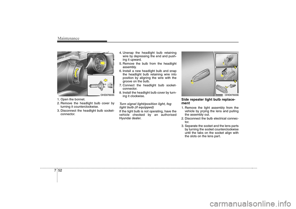
1. Open the bonnet.
2. Remove the headlight bulb cover by
turning it counterclockwise.
3. Disconnect the headlight bulb socket- connector. 4. Unsnap the headlight bulb retaining
wire by depressing the end and push-
ing it upward.
5. Remove the bulb from the headlight assembly.
6. Install a new headlight bulb and snap the headlight bulb retaining wire into
position by aligning the wire with the
groove on the bulb.
7. Connect the headlight bulb socket- connector.
8. Install the headlight bulb cover by turn- ing it clockwise.
Turn signal light/position light, fog
light bulb (if equipped)
If the light bulb is not operating, have the
vehicle checked by an authorised
Hyundai dealer. Side repeater light bulb replace- ment
1. Remove the light assembly from the
vehicle by prying the lens and pulling
the assembly out.
2. Disconnect the bulb electrical connec- tor.
3. Separate the socket and the lens parts by turning the socket counterclockwise
until the tabs on the socket align with
the slots on the lens part.
OHD076035OHD076036
Page 279 of 308
Maintenance
54
7
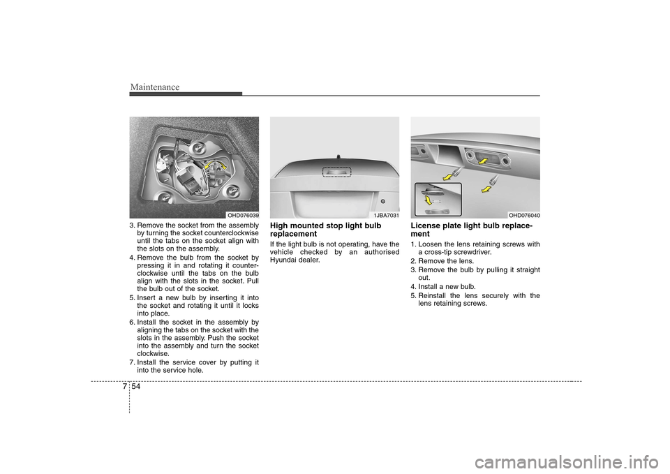
3. Remove the socket from the assembly
by turning the socket counterclockwise
until the tabs on the socket align with
the slots on the assembly.
4. Remove the bulb from the socket by pressing it in and rotating it counter-
clockwise until the tabs on the bulb
align with the slots in the socket. Pull
the bulb out of the socket.
5. Insert a new bulb by inserting it into the socket and rotating it until it locks
into place.
6. Install the socket in the assembly by aligning the tabs on the socket with the
slots in the assembly. Push the socket
into the assembly and turn the socket
clockwise.
7. Install the service cover by putting it into the service hole. High mounted stop light bulb replacement
If the light bulb is not operating, have the
vehicle checked by an authorised
Hyundai dealer.
License plate light bulb replace- ment
1. Loosen the lens retaining screws with
a cross-tip screwdriver.
2. Remove the lens.
3. Remove the bulb by pulling it straight out.
4. Install a new bulb.
5. Reinstall the lens securely with the lens retaining screws.
OHD0760391JBA7031OHD076040