Hyundai H-1 (Grand Starex) 2003 Repair Manual
Manufacturer: HYUNDAI, Model Year: 2003, Model line: H-1 (Grand Starex), Model: Hyundai H-1 (Grand Starex) 2003Pages: 173, PDF Size: 3.68 MB
Page 61 of 173

INSTRUMENTS & CONTROLS
INSTRUMENTS & CONTROLS INSTRUMENTS & CONTROLS
INSTRUMENTS & CONTROLS
INSTRUMENTS & CONTROLS
2-22 B510D01Y-AAT
OUTSIDE REARVIEW MIRROR HEAT-
OUTSIDE REARVIEW MIRROR HEAT- OUTSIDE REARVIEW MIRROR HEAT-
OUTSIDE REARVIEW MIRROR HEAT-
OUTSIDE REARVIEW MIRROR HEAT-
ER (If installed)
ER (If installed) ER (If installed)
ER (If installed)
ER (If installed)
B510D01Y-AAG
The outside rearview mirror heater is actuated
in connection with rear window defroster. So, toheat the outside rearview mirror glass, push inthe switch for rear window defroster. The rear-
view mirror glass will be heated for defrosting ordefogging and will give you improved rear vi-
sion in all weather conditions. Push the switch
again to turn the heater off. The outside rear-view mirror heater automatically turns itself offafter 15 minutes. B450A01S-AAT
DRINK HOLDER (If installed)
DRINK HOLDER (If installed) DRINK HOLDER (If installed)
DRINK HOLDER (If installed)
DRINK HOLDER (If installed)
The drink holder is located on the front mainconsole for holding cups or cans in its holes.
The drink holder can be used by pushing it at itstop edge. CAUTION:
CAUTION: CAUTION:
CAUTION:
CAUTION:
Place the drink holder in its original position
Place the drink holder in its original position Place the drink holder in its original position
Place the drink holder in its original position
Place the drink holder in its original position
while not in
while not in while not in
while not in
while not in
use.use.
use.use.
use.
WARNING:
WARNING: WARNING:
WARNING:
WARNING:
Do not place anything else on the drink
Do not place anything else on the drink Do not place anything else on the drink
Do not place anything else on the drink
Do not place anything else on the drink
holder. Such objects
holder. Such objects holder. Such objects
holder. Such objects
holder. Such objects can be thrown out,
can be thrown out, can be thrown out,
can be thrown out,
can be thrown out,
possibly injuring persons in the vehicle dur-
possibly injuring persons in the vehicle dur- possibly injuring persons in the vehicle dur-
possibly injuring persons in the vehicle dur-
possibly injuring persons in the vehicle dur-
ing sudden
ing sudden ing sudden
ing sudden
ing sudden braking or in an accident.
braking or in an accident. braking or in an accident.
braking or in an accident.
braking or in an accident.
C370B01P-GAT
Electric Type (If installed)
Electric Type (If installed) Electric Type (If installed)
Electric Type (If installed)
Electric Type (If installed)
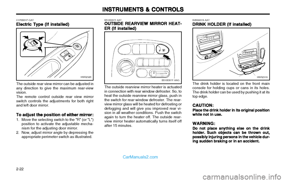
The outside rear view mirror can be adjusted in
any direction to give the maximum rear-viewvision.
The remote control outside rear view mirror
switch controls the adjustments for both rightand left door mirror.
To adjust the position of either mirror:
To adjust the position of either mirror: To adjust the position of either mirror:
To adjust the position of either mirror:
To adjust the position of either mirror:
1. Move the selecting switch to the "R" (or "L")
position to activate the adjustable mecha- nism for the adjusting door mirror.
2. Now, adjust mirror angle by depressing the appropriate perimeter switch as illustrated.
HSR2320HSR2318
Page 62 of 173

2-23
INSTRUMENTS & CONTROLS
INSTRUMENTS & CONTROLS INSTRUMENTS & CONTROLS
INSTRUMENTS & CONTROLS
INSTRUMENTS & CONTROLS
C400A02P-GAT
CIGARETTE LIGHTER
CIGARETTE LIGHTER CIGARETTE LIGHTER
CIGARETTE LIGHTER
CIGARETTE LIGHTER The cigarette lighter can be used while the ignition switch is at either the "ON" or "ACC". Touse the cigarette lighter, push it all the way intoits socket. The lighter will automatically return to its original position with a "click" when ready. Pull it out for use.
CAUTION:
CAUTION: CAUTION:
CAUTION:
CAUTION:
oo
oo
o Something is wrong with the cigarette
Something is wrong with the cigarette Something is wrong with the cigarette
Something is wrong with the cigarette
Something is wrong with the cigarette
lighter if it does not pop back out within
lighter if it does not pop back out within lighter if it does not pop back out within
lighter if it does not pop back out within
lighter if it does not pop back out within
approximately 8~18 seconds of being
approximately 8~18 seconds of being approximately 8~18 seconds of being
approximately 8~18 seconds of being
approximately 8~18 seconds of being
pushed in. Leaving the cigarette lighter
pushed in. Leaving the cigarette lighter pushed in. Leaving the cigarette lighter
pushed in. Leaving the cigarette lighter
pushed in. Leaving the cigarette lighter
pushed in for an extended period could
pushed in for an extended period could pushed in for an extended period could
pushed in for an extended period could
pushed in for an extended period could
cause a fire. If it does not pop out by
cause a fire. If it does not pop out by cause a fire. If it does not pop out by
cause a fire. If it does not pop out by
cause a fire. If it does not pop out by
itself, pull it out and have the problem
itself, pull it out and have the problem itself, pull it out and have the problem
itself, pull it out and have the problem
itself, pull it out and have the problem
corrected at an authorized HYUNDAI
corrected at an authorized HYUNDAI corrected at an authorized HYUNDAI
corrected at an authorized HYUNDAI
corrected at an authorized HYUNDAI
dealer.
dealer. dealer.
dealer.
dealer. C410A01P-GAT
FRONT ASHTRAY
FRONT ASHTRAY FRONT ASHTRAY
FRONT ASHTRAY
FRONT ASHTRAY
Pull out the ashtray to open. To remove the
ashtray, pull it out while pressing the stubber. oo
oo
o Do not use electric accessories or equip-
Do not use electric accessories or equip- Do not use electric accessories or equip-
Do not use electric accessories or equip-
Do not use electric accessories or equip-
ment other than the Hyundai genuine
ment other than the Hyundai genuine ment other than the Hyundai genuine
ment other than the Hyundai genuine
ment other than the Hyundai genuine
parts in the socket.
parts in the socket. parts in the socket.
parts in the socket.
parts in the socket.
HSR2315
HSR2317
GS20250A
C420A01P-GAT
REAR ASHTRAY
REAR ASHTRAY REAR ASHTRAY
REAR ASHTRAY
REAR ASHTRAY
Type A (If installed)
Type A (If installed) Type A (If installed)
Type A (If installed)
Type A (If installed)
Pull the ashtray downward to open. To remove
the ashtray, pull it out while pressing the stubber.
Page 63 of 173

INSTRUMENTS & CONTROLS
INSTRUMENTS & CONTROLS INSTRUMENTS & CONTROLS
INSTRUMENTS & CONTROLS
INSTRUMENTS & CONTROLS
2-24
C610A02P-GAG
Lever type23 4
1
There are four controls for the heating and cooling system. They are:
1. Fan Speed Control. This is used to turn the fan on and select thefan speed.
C610A01P-GAT
HEATING AND COOLING
HEATING AND COOLING HEATING AND COOLING
HEATING AND COOLING
HEATING AND COOLING
Rotary and push button type
C610A01P-GAG43
21
C430A01P-GAT
Type B (If installed)
Type B (If installed) Type B (If installed)
Type B (If installed)
Type B (If installed) C440A01P-GAT
DIGITAL CLOCK (If installed)
DIGITAL CLOCK (If installed) DIGITAL CLOCK (If installed)
DIGITAL CLOCK (If installed)
DIGITAL CLOCK (If installed)
C440A01P-GAGC430A01P-GAG
To use the ashtray, open up the lid. To remove the ashtray, open the lid and lift
upward holding the lid. The digital clock indicates the time while the
ignition switch is at either the "ON" or "ACC" position.
Set the time by pressing the various buttons as
described below.
HH
HH
H --
--
- To adjust the hours
MM
MM
M --
--
- To adjust the minutes
RR
RR
R --
--
- To reset the minutes to zero.
Example: 10 : 01 - 10 : 29 ................... change to 10 : 00 10 : 30 - 10 : 59 ................... change to 11 : 00
Page 64 of 173

2-25
INSTRUMENTS & CONTROLS
INSTRUMENTS & CONTROLS INSTRUMENTS & CONTROLS
INSTRUMENTS & CONTROLS
INSTRUMENTS & CONTROLS
C640A01P-GATVENTILATION
VENTILATION VENTILATION
VENTILATION
VENTILATION To operate the ventilation system:
o Set the air intake control to the "Fresh"
position.
o To direct all intake air to the dashboard vents, set the air flow control to the "Face" position.
o Adjust the fan speed control to the desired speed.
o Set the temperature control between "Cool" and "Warm".
C620A01P-GAT
HEATING CONTROLS
HEATING CONTROLS HEATING CONTROLS
HEATING CONTROLS
HEATING CONTROLS
For normal heater operation, move the air in-
take control to the "Fresh" position and the airflow control to the "Floor" position.
For faster heating, the air intake control should
be placed in the intermediate position between"Fresh" and "Recirc".
For quickest heating, the control should be in
the "Recirc" position.
If the windows fog up, move the air flow control
to the "Def" (defroster) position and the airintake control to "Fresh". For maximum heat, move the temperature con-
trol to "Warm". C630A01P-GAT
BI-LEVEL HEATING
BI-LEVEL HEATING BI-LEVEL HEATING
BI-LEVEL HEATING
BI-LEVEL HEATING
Your Hyundai is equipped with bi-level heating
controls. This makes it possible to have coolerair from the dashboard vents and warmer airfrom the floor outlets at the same time. To usethis feature,
o Set the air intake control at the "Fresh" position.
o Set the air flow control at the "Bi-Level" position.
o Set the temperaute control between "Cool" and "Warm"
2. Air Intake Control.
This allows you to select fresh ( ) outside air or to recirculate ( ) inside air.
3. Air Flow Control. This is used to direct the flow of air. Air canbe directed to the floor, dashboard outlets orwindshield. Five symbols are used to repre-sent Face ( ), Bi-Level ( ), Floor ( ),Floor-Defrost ( ) and Defrost ( ) airpositions.
4. Temperature Control This is used to turn the heater on and offand to select the degree of heating desired.
B710B01A-AAT
CENTER VENTILATOR
CENTER VENTILATOR CENTER VENTILATOR
CENTER VENTILATOR
CENTER VENTILATOR
B710B01P
The center ventilators are located in the middle
of the dashboard.
To change the direction of the airflow, turn the
control knob on the middle of the ventilator as desired.
Page 65 of 173

INSTRUMENTS & CONTROLS
INSTRUMENTS & CONTROLS INSTRUMENTS & CONTROLS
INSTRUMENTS & CONTROLS
INSTRUMENTS & CONTROLS
2-26 C670A01P-GAT
Operation Tips
Operation Tips Operation Tips
Operation Tips
Operation Tips
o To keep dust or unpleasant fumes from en-
tering the vehicle through the ventilation sys- tem, temporarily set the air intake control at"Recirc". Be sure to return the control to"Fresh" when the irritation has passed tokeep fresh air in the vehicle.This will help keep the driver alert and com-fortable.
o Air for the heating/cooling system is drawn in through the grilles just ahead of the wind-shield. Care should be taken that these arenot blocked by leaves, snow, ice or otherobstructions.
o Set the temperature control (3) to a comfort-
ably warm position.
o Set the fan speed control (4) to position 3 or 4.
o If the vehicle is equipped with a A/C sys- tem, turn the A/C switch (5) on for in-creased defogging action.
NOTE:
NOTE: NOTE:
NOTE:
NOTE:
In high humidity areas, the A/C can be used
In high humidity areas, the A/C can be used In high humidity areas, the A/C can be used
In high humidity areas, the A/C can be used
In high humidity areas, the A/C can be used
with the air intake in the "Recirc" position
with the air intake in the "Recirc" position with the air intake in the "Recirc" position
with the air intake in the "Recirc" position
with the air intake in the "Recirc" position
for increased defogging action.
for increased defogging action. for increased defogging action.
for increased defogging action.
for increased defogging action.
C650A01P-GAT
SIDE VENTILATOR
SIDE VENTILATOR SIDE VENTILATOR
SIDE VENTILATOR
SIDE VENTILATOR
C650A01P-GAG
The side ventilators are located on each side of the dash board. The side vent knobs controlthe amount of outside air entering the vehiclethrough the side vents. These vents can alsobe closed, so no air enters through the sidevents. To change the direction of the air flow,turn the control knobs as desired. C660A01P-GAT
DEFROSTING/DEFOGGING
DEFROSTING/DEFOGGING DEFROSTING/DEFOGGING
DEFROSTING/DEFOGGING
DEFROSTING/DEFOGGINGC660A01P-GAG
1 2
453
To use the heating/ventilation system to defrost
or defog the windshield:
o Set the air intake control (1) to the "Fresh" position.
o Set the air flow control (2) to the "Def" position.
C660B01P
Page 66 of 173

2-27
INSTRUMENTS & CONTROLS
INSTRUMENTS & CONTROLS INSTRUMENTS & CONTROLS
INSTRUMENTS & CONTROLS
INSTRUMENTS & CONTROLS
C680A02P-GAG
C690A01P-GAT
Dehumidified heating
Dehumidified heating Dehumidified heating
Dehumidified heating
Dehumidified heating
C690A01P-GAG
C680A01P-GAG
C680A01P-GAT
AIR CONDITIONER OPERATION
AIR CONDITIONER OPERATION AIR CONDITIONER OPERATION
AIR CONDITIONER OPERATION
AIR CONDITIONER OPERATION
(If installed)
(If installed) (If installed)
(If installed)
(If installed)
Cooling
Cooling Cooling
Cooling
Cooling
To use the air conditioner to cool interior:
o Set the side vent control to "OFF", to shut off outside air entry. o Turn on the fan control switch.
o Turn on the air conditioner switch by push-
ing in on the switch. The air conditioner indicator light should come on at the sametime.
o Set the air intake control to the "Fresh" position.
o Set the temperature control to the "Cool" position. ("Cool" provides maximum cooling. The tem- perature may be moderated by moving thecontrol toward "Warm".)
o Adjust the fan control to the desired speed. For greater cooling, turn the fan control toone of the higher speeds or temporarilyselect the "Recirc" position on the air intakecontrol.
C690A02P-GAG
For dehumidified heating:
o Turn on the fan control switch.
o Turn on the air conditioner switch by pushing in on the switch. The air conditioner indicator light should come on at the same time.
o Set the air intake control to "Fresh".
o Set the air flow control to "Face".
o Adjust the fan control to the desired speed. For more rapid action, set the fan at one of the higher speeds.
o Adjust the temperature control to provide the desired amount of warmth.
Page 67 of 173

INSTRUMENTS & CONTROLS
INSTRUMENTS & CONTROLS INSTRUMENTS & CONTROLS
INSTRUMENTS & CONTROLS
INSTRUMENTS & CONTROLS
2-28 C730A01P-GAT
CONTROL PANEL
CONTROL PANEL CONTROL PANEL
CONTROL PANEL
CONTROL PANEL
C730A01P-1
213
REAR HEATER & A/CON (ROTARY TYPE)
C730A02P-1
REAR HEATER & A/CON (LEVER TYPE)
1
2 3
1.1.
1.1.
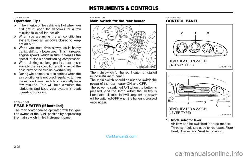
1. Mode selector lever
Mode selector lever Mode selector lever
Mode selector lever
Mode selector lever Air flow can be switched in three modes. Three symbols are used to represent FloorHeat, Bi-level and Vent Air position.
C700A01P-GAT
Operation Tips
Operation Tips Operation Tips
Operation Tips
Operation Tips
o If the interior of the vehicle is hot when you
first get in, open the windows for a few minutes to expel the hot air.
o When you are using the air conditioning system, keep all windows closed to keephot air out.
o When you must drive slowly, as in heavy traffic, shift to a lower gear. This increasesengine speed, which in turn increases thespeed of the air conditioning compressor.
o When driving up long grades, turn occa- sionally the air conditioner off to avoid thepossibility of the engine overheating.
o During winter months or in periods when the air conditioner is not used regularly, turn onthe air conditioner switch occasionally for afew minutes. This will help circulate thelubricants and keep your system in peakoperating condition.
C710A01P-GAT REAR HEATER (If installed)
REAR HEATER (If installed) REAR HEATER (If installed)
REAR HEATER (If installed)
REAR HEATER (If installed)
The rear heater can be operated with the igni-
tion switch at the "ON" position by depressingthe main switch in the instrument panel. C720A01P-GAT
Main switch for the rear heater
Main switch for the rear heater Main switch for the rear heater
Main switch for the rear heater
Main switch for the rear heater
C720A01P-GAG
The main switch for the rear heater is installed
in the instrument panel.
The main switch should be used to switch the
power of the rear heater ON and OFF.
The power is switched ON when the button is
pressed, and the lamp within the switch is illuminated. Illumination will stop and the powerwill be switched OFF when the button is pressedonce again.
Page 68 of 173

2-29
INSTRUMENTS & CONTROLS
INSTRUMENTS & CONTROLS INSTRUMENTS & CONTROLS
INSTRUMENTS & CONTROLS
INSTRUMENTS & CONTROLS
C750A03P-GATOVERHEAD AIR CONDITIONING
OVERHEAD AIR CONDITIONING OVERHEAD AIR CONDITIONING
OVERHEAD AIR CONDITIONING
OVERHEAD AIR CONDITIONING
(If installed)
(If installed) (If installed)
(If installed)
(If installed)
C750A01P-1
1
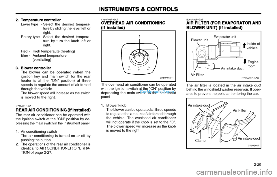
The overhead air conditioner can be operated
with the ignition switch at the "ON" position by depressing the main switch in the instrumentpanel.
1. Blower knob
The blower can be operated at three speeds to regulate the amount of air forced throughthe vehicle. The overhead air conditionerwill not operate if the knob is set to the "O". The blower speed will increase as the knob is moved to the right.
2.2.
2.2.
2. Temperature controller
Temperature controller Temperature controller
Temperature controller
Temperature controller
Lever type - Select the desired tempera-
ture by sliding the lever left or right.
Rotary type - Select the desired tempera- ture by turn the knob left orright.
Red - High temperaute (heating)
Blue - Ambient temperature(ventilating)
3.3.
3.3.
3. Blower controller
Blower controller Blower controller
Blower controller
Blower controllerThe blower can be operated (when the ignition key and main switch for the rearheater is at the "ON" position) at threespeeds to regulate the amount of air forcedthrough the vehicle. The blower speed will increase as the switch is moved to the right.
C740A01P-GAT REAR AIR CONDITIONING (If installed)
REAR AIR CONDITIONING (If installed) REAR AIR CONDITIONING (If installed)
REAR AIR CONDITIONING (If installed)
REAR AIR CONDITIONING (If installed)
The rear air conditioner can be operated with
the ignition switch at the "ON" position by de-pressing the main switch in the instrument panel.
1. Air conditioning switch
The air conditioning is turned on or off by pushing the button.
2. The operations of the rear air conditioner is identical to AIR CONDITIONER OPERRA-TION of page 2-27.
C760A01P-GAG
B760A02P-GAT
AIR FILTER (FOR EVAPORATOR AND
AIR FILTER (FOR EVAPORATOR AND AIR FILTER (FOR EVAPORATOR AND
AIR FILTER (FOR EVAPORATOR AND
AIR FILTER (FOR EVAPORATOR AND
BLOWER UNIT) (If installed)
BLOWER UNIT) (If installed) BLOWER UNIT) (If installed)
BLOWER UNIT) (If installed)
BLOWER UNIT) (If installed)
The air filter is located in the air intake duct
behind the windshield washer reservoir. It oper- ates to prevent the pollutant entering the car.
C760B01PClamp
Air intake duct
Air intake duct
Air Filter
Air intake duct
Engine room
Evaporator unit
Blower unit
Air Filter Inside ofvehicle
Page 69 of 173

INSTRUMENTS & CONTROLS
INSTRUMENTS & CONTROLS INSTRUMENTS & CONTROLS
INSTRUMENTS & CONTROLS
INSTRUMENTS & CONTROLS
2-30 Replacement instructions:
1. Open the hood.
2. Remove the clamps (5 EA) on the air in- take duct and replace the filter.
3. Installation is the reverse order of the disas- sembly.
CAUTION:
CAUTION: CAUTION:
CAUTION:
CAUTION:
oo
oo
o Replace the filter every 20,000 km (12,000
Replace the filter every 20,000 km (12,000 Replace the filter every 20,000 km (12,000
Replace the filter every 20,000 km (12,000
Replace the filter every 20,000 km (12,000
miles) or once a year. If the car is being
miles) or once a year. If the car is being miles) or once a year. If the car is being
miles) or once a year. If the car is being
miles) or once a year. If the car is being
driven in severe conditions such as dusty,
driven in severe conditions such as dusty, driven in severe conditions such as dusty,
driven in severe conditions such as dusty,
driven in severe conditions such as dusty,
rough roads, more frequent air filter in-
rough roads, more frequent air filter in- rough roads, more frequent air filter in-
rough roads, more frequent air filter in-
rough roads, more frequent air filter in-
spections and changes are required.
spections and changes are required. spections and changes are required.
spections and changes are required.
spections and changes are required.
oo
oo
o When the air flow rate is suddenly de-
When the air flow rate is suddenly de- When the air flow rate is suddenly de-
When the air flow rate is suddenly de-
When the air flow rate is suddenly de-
creased, it must be checked at autho-
creased, it must be checked at autho- creased, it must be checked at autho-
creased, it must be checked at autho-
creased, it must be checked at autho-
rized dealer.
rized dealer. rized dealer.
rized dealer.
rized dealer.
Page 70 of 173

2-31
INSTRUMENTS & CONTROLS
INSTRUMENTS & CONTROLS INSTRUMENTS & CONTROLS
INSTRUMENTS & CONTROLS
INSTRUMENTS & CONTROLS
SSAR011ASSAR012A
SSAR010A
AM reception
Ionosphere
AM signal reception is usually better than FM
reception. This is because AM radio waves are transmitted at low frequency. These long, lowfrequency radio waves can follow the curvatureof the earth rather than travelling straight outinto the atmosphere. In addition, they curvearound obstructions so that they can providebetter signal coverage. Because of this, clearAM broadcasts can be received at greater dis-tances than FM broadcasts. Iron bridges
Unobstructed area
Mountains
Buildings
FM broadcasts are transmitted at high frequen-
cy and do not bend to follow the earth's surface. Because of this, FM broadcasts generally be-gin to fade at short distances from the station.Also, FM signals are easily affected by build-ings, mountains, or other obstructions. Thesecan result in certain listening conditions whichmight lead you to believe a problem exists withyour radio. The following conditions are normaland do not indicate radio trouble:
B750A01A-AAT
STEREO SOUND SYSTEM
STEREO SOUND SYSTEM STEREO SOUND SYSTEM
STEREO SOUND SYSTEM
STEREO SOUND SYSTEM
How Car Audio Works
How Car Audio Works How Car Audio Works
How Car Audio Works
How Car Audio Works
Ionosphere
FM reception
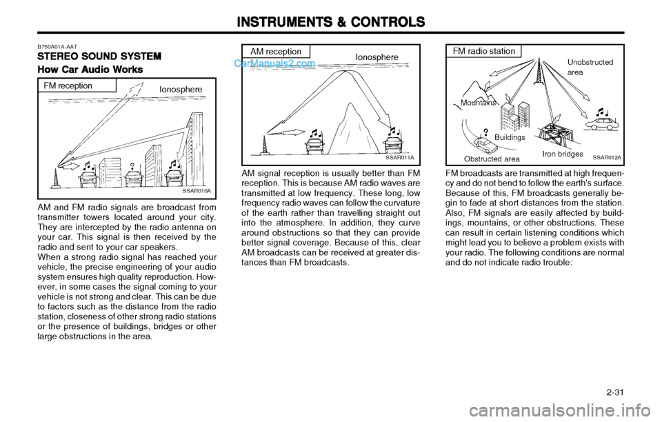
AM and FM radio signals are broadcast from
transmitter towers located around your city.They are intercepted by the radio antenna onyour car. This signal is then received by theradio and sent to your car speakers.
When a strong radio signal has reached your
vehicle, the precise engineering of your audiosystem ensures high quality reproduction. How-ever, in some cases the signal coming to yourvehicle is not strong and clear. This can be dueto factors such as the distance from the radiostation, closeness of other strong radio stationsor the presence of buildings, bridges or otherlarge obstructions in the area. FM radio station
Obstructed area